Kompetenz in Glas – von der Komponente bis zur Anlage - QVF ...
Kompetenz in Glas – von der Komponente bis zur Anlage - QVF ...
Kompetenz in Glas – von der Komponente bis zur Anlage - QVF ...

Erfolgreiche ePaper selbst erstellen
Machen Sie aus Ihren PDF Publikationen ein blätterbares Flipbook mit unserer einzigartigen Google optimierten e-Paper Software.
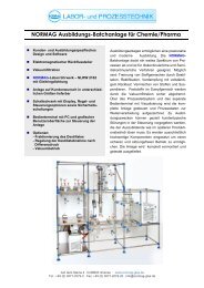
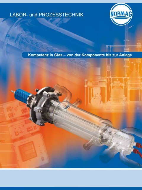
<strong>Kompetenz</strong> <strong>in</strong> <strong>Glas</strong> – <strong>von</strong> <strong>der</strong> <strong>Komponente</strong> <strong>bis</strong> <strong>zur</strong> <strong>Anlage</strong>
Konstruktion / Fertigung<br />
Thür<strong>in</strong>gen und <strong>in</strong>sbeson<strong>der</strong>e Ilmenau ist mit <strong>der</strong> Geschichte und <strong>der</strong> Entwicklung <strong>der</strong> <strong>in</strong>dustriellen <strong>Glas</strong>verarbeitung eng verbunden.<br />
Über Generationen h<strong>in</strong>weg wird <strong>in</strong> Ilmenau <strong>Glas</strong> geblasen, dem Standort <strong>der</strong> NORMAG Labor- und Prozesstechnik GmbH.<br />
Diese <strong>Kompetenz</strong> <strong>in</strong> <strong>Glas</strong>, die ständige Verbesserung <strong>der</strong> Fertigungsmethoden sowie die langjährige enge Kooperation mit <strong>der</strong><br />
europäischen Chemie- und Pharma<strong>in</strong>dustrie hat die Entwicklung unserer Firma vorangetrieben.<br />
Das Produktionsprofil <strong>der</strong> NORMAG Labor- und Prozesstechnik GmbH reicht heute <strong>von</strong> hochwertigen <strong>Komponente</strong>n <strong>bis</strong> <strong>zur</strong> kompletten<br />
<strong>Anlage</strong> vom Labor <strong>bis</strong> zum Prozess und wird geme<strong>in</strong>sam mit unseren Kunden ständig weiter entwickelt.<br />
Konstruktion<br />
• Standard- und Son<strong>der</strong>bauteile<br />
• Machbarkeitsüberprüfung<br />
• CAD-Konstruktion<br />
• Dokumentation<br />
Fertigung<br />
Die Fertigung umfasst ausgehend <strong>von</strong> Borosilikatglas 3.3<br />
• <strong>Glas</strong>apparatebau manuell und masch<strong>in</strong>ell<br />
• <strong>Glas</strong>schleiferei<br />
• Beschichtung / Verspiegelung<br />
• Mechanikbauteile für <strong>Glas</strong>apparate<br />
• Elektronikbauteile für <strong>Glas</strong>apparate<br />
Montage<br />
Die Montage erfolgt <strong>von</strong> <strong>der</strong> <strong>Komponente</strong> <strong>bis</strong> <strong>zur</strong> <strong>Anlage</strong><br />
• Mechanische Montage<br />
• MSR-Montage<br />
• Inbetriebnahme<br />
• Service<br />
Qualität<br />
Qualität ist <strong>in</strong>tegrativer Bestandteil jedes Herstellschrittes<br />
• Fertigungs<strong>in</strong>tegrierte Kontrolle<br />
• Endkontrolle <strong>der</strong> Bauteile<br />
• Funktionstest<br />
• NORMAG-Gütezeichen auf alle geprüften Bauteile
Halbzeuge / <strong>Komponente</strong>n<br />
Alle <strong>in</strong> <strong>der</strong> glastechnischen Fertigung produzierten Bauteile s<strong>in</strong>d aus Borosilikatglas 3.3 gefertigt. Die <strong>in</strong> Komb<strong>in</strong>ation mit Borosilikatglas<br />
3.3 verarbeiteten Werkstoffe s<strong>in</strong>d chemisch und thermisch hochresistent.<br />
Die standardisierten <strong>Komponente</strong>n und Apparate s<strong>in</strong>d <strong>in</strong> unserem Katalog zusammengefasst. Daneben liefern wir Lösungen für<br />
spezielle Anwendungen und kundenspezifische Son<strong>der</strong>bauteile.<br />
Röhren / Kapillaren / Stäbe<br />
aus Borosilikatglas 3.3 nach DIN ISO 3585<br />
• hohe Präzision bei allen Abmessungen<br />
• chemisch und thermisch hochresistent<br />
Halbzeuge / Zubehör<br />
• Hochvakuumdichte Hähne<br />
• Ventile<br />
• Schliffe<br />
• <strong>Glas</strong>hohlkörper<br />
• verschiedene Laborflansche und technische Flansche<br />
• Verb<strong>in</strong>dungstechnik<br />
• Gestellbau<br />
Bauteile / <strong>Komponente</strong>n<br />
• Allgeme<strong>in</strong>e <strong>Glas</strong>schliffgeräte<br />
• Laborglasgeräte mit speziellen Know-How<br />
• Standardbauteile und Bauteile mit speziellen Know-How<br />
• Destillationsbauteile<br />
• Reaktionsgefäße<br />
• Son<strong>der</strong>anfertigungen auf Kundenwunsch<br />
MSR-Technik<br />
Qualität ist <strong>in</strong>tegrativer Bestandteil jedes Herstellschrittes<br />
• Sensoren für alle gängigen Messgrößen<br />
• Aktoren wie pneumatische Stellventile<br />
• Steuer- und Regelungstechnik<br />
• Software
Apparate / <strong>Anlage</strong>n<br />
Die Komb<strong>in</strong>ation <strong>von</strong> glasbläserischem Können sowie konstruktiver und verfahrenstechnischer Erfahrung ermöglichen uns den<br />
Bau <strong>von</strong> Apparaten und verfahrenstechnischen <strong>Anlage</strong>n. Durch die Ausstattung dieser Apparate und <strong>Anlage</strong>n mit MSR-Technik<br />
<strong>bis</strong> h<strong>in</strong> <strong>zur</strong> Prozessvisualisierung liefern wir kundenspezifische Komplettlösungen vom Labor <strong>bis</strong> zum Prozess.<br />
Eng<strong>in</strong>eer<strong>in</strong>g<br />
• Individuelle Kundenabstimmung<br />
• Verfahrenstechnische Unterstützung<br />
• Konstruktion<br />
• Projektmanagement<br />
• Montage<br />
• Inbetriebnahme<br />
• Dokumentation<br />
Apparate<br />
Apparate mit speziellen Know-How wie<br />
• Gleichgewichtsapparatur<br />
• Lösungsmittel-Umlaufapparaturen<br />
• Extraktive Wasserdampfdestillation<br />
• Fest-Flüssig-Extraktoren<br />
• Flüssig-Flüssig-Extraktoren<br />
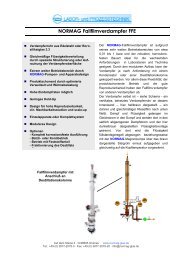
• Kurzweg-, Dünnschicht- und Fallfilmverdampfer<br />
<strong>Anlage</strong>n<br />
<strong>Anlage</strong>n aus Borosilikatglas 3.3 <strong>zur</strong><br />
• Reaktion<br />
• Destillation und Rektifikation<br />
• Extraktion<br />
• Ab- und Desorption<br />
• Adsorption<br />
• Kristallisation
Competence <strong>in</strong> <strong>Glas</strong>s – from the component to the unit
Construction / Production<br />
Thur<strong>in</strong>gia and especially Ilmenau have a strong relationship to the history and development of <strong>in</strong>dustrial glass form<strong>in</strong>g. <strong>Glas</strong>s has<br />
been blown for many generations <strong>in</strong> Ilmenau, the site of NORMAG Labor- und Prozesstechnik GmbH.<br />
This competence <strong>in</strong> glass, the cont<strong>in</strong>ual improvement of our production methods and a close co-operation with the European<br />
chemical and pharmaceutical <strong>in</strong>dustries throughout years have pushed the development of our company.<br />
The product range of NORMAG Labor- und Prozesstechnik GmbH reaches from sophisticated components to complete units for<br />
laboratory and process, and has been cont<strong>in</strong>ually developed together with our customers.<br />
Construction<br />
• Standard components and special components<br />
• Feasibility studies<br />
• CAD construction<br />
• Documentation<br />
Production<br />
Our production <strong>in</strong>cludes on the basis of Borosilicate glass 3.3<br />
• <strong>Glas</strong>s apparatus, manually or mach<strong>in</strong>e manufactured<br />
• <strong>Glas</strong>s gr<strong>in</strong>d<strong>in</strong>g<br />
• Surface coat<strong>in</strong>g / metallis<strong>in</strong>g<br />
• Mechanical components for glass apparatus<br />
• Electronics components for glass apparatus<br />
Assembly<br />
The assembly covers components and units<br />
• Mechanical assembly<br />
• Measurement and control technology<br />
• Commission<strong>in</strong>g<br />
• Service<br />
Quality<br />
Quality is an <strong>in</strong>tegrated part of every production stage<br />
• Production-<strong>in</strong>tegrated control<br />
• F<strong>in</strong>al control of the components<br />
• Operat<strong>in</strong>g test<br />
• NORMAG quality mark on all checked components
Semi-f<strong>in</strong>ished products / Components<br />
All glass components are manufactured from Borosilicate glass 3.3, completed by the use of other highly chemical and thermal<br />
resistant materials.<br />
Standardised components and apparatus are shown <strong>in</strong> our catalogue.<br />
Furthermore, we provide solutions for special applications and customer-specific components.<br />
Tubes / Capillaries / Rods<br />
Made of Borosilicate glass 3.3 accord<strong>in</strong>g to DIN ISO 3585<br />
• High precision <strong>in</strong> all dimensions<br />
• Chemical and thermal highly resistant<br />
Semi-f<strong>in</strong>ished products / Accessory<br />
• High vacuum tight stopcocks<br />
• Valves<br />
• Gr<strong>in</strong>d<strong>in</strong>gs<br />
• Hollow glass parts<br />
• Different laboratory flanges and technical flanges<br />
• Connections<br />
• Frame work<br />
Components<br />
• General glassware<br />
• Specialised glassware<br />
• Standard components and specialised components<br />
• Distillation components<br />
• Reaction vessels<br />
• Special components<br />
Measurement and control technology<br />
• Sensors for all common measur<strong>in</strong>g data<br />
• Actors as pneumatic adjustment valves<br />
• Measurement and control systems<br />
• Software
Apparatus / Units<br />
The comb<strong>in</strong>ation of our glassblow<strong>in</strong>g skills, constructive and process-technical experiences enable us to built apparatus and<br />
process-eng<strong>in</strong>eer<strong>in</strong>g units. Due to the equipment of our apparatus and units with measurement and control technology up to process<br />
visualisation we are able to supply customer specific solutions reach<strong>in</strong>g from laboratory size to process.<br />
Eng<strong>in</strong>eer<strong>in</strong>g<br />
• Individual customer co-ord<strong>in</strong>ation<br />
• Process-technical support<br />
• Construction<br />
• Project management<br />
• Assembly<br />
• Commission<strong>in</strong>g<br />
• Documentation<br />
Apparatus<br />
Specialised Apparatus<br />
• Equilibration apparatus<br />
• Solvent circulat<strong>in</strong>g apparatus<br />
• Extractive steam distillation<br />
• Solid-liquid extraction<br />
• Liquid-liquid extraction<br />
• Short path evaporator<br />
• Th<strong>in</strong> film / Fall<strong>in</strong>g film evaporator<br />
Units<br />
Units made of Borosilicate glass 3.3<br />
• Reaction<br />
• Distillation and rectification<br />
• Extraction<br />
• Absorption / Desorption<br />
• Adsorption<br />
• Crystallisation
Technische Informationen<br />
Technical Informations
ALLGEMEINES<br />
Alle <strong>in</strong> diesem Katalog beschriebenen Halbzeuge <strong>zur</strong> glasbläserischen Weiterverarbeitung<br />
wie Rohre, Stäbe, Verb<strong>in</strong>dungsstücke (z.B. mit Schliffen, Kle<strong>in</strong>flanschen etc.),<br />
Hähne und Ventile sowie alle Schliffgeräte (z.B. Kolonnenbauteile), <strong>Komponente</strong>n<br />
(z.B. Reaktionsgefäße) und Apparaturen s<strong>in</strong>d aus dem auch im technischen <strong>Glas</strong>apparatebau<br />
gebräuchlichen Werkstoff Borosilicatglas 3.3 hergestellt. Dieses Material<br />
zeichnet sich aus durch e<strong>in</strong>e nahezu universelle chemische Beständigkeit gegenüber<br />
den <strong>in</strong> <strong>der</strong> Praxis produktseitig vorkommenden Medien, e<strong>in</strong>en niedrigen thermischen<br />
Ausdehnungskoeffizienten sowie e<strong>in</strong>e hohe Warmfestigkeit und Temperaturwechselbeständigkeit.<br />
Erkennbar s<strong>in</strong>d unsere Produkte an <strong>der</strong> Kennzeichnung<br />
Mit dem Firmenlogo wollen wir zweierlei zum Ausdruck br<strong>in</strong>gen:<br />
- Nach Übernahme <strong>der</strong> Fa. NORMAG-Labor- und Verfahrenstechnik GmbH und <strong>der</strong>en<br />
Know-how liefern wir Halbzeuge für <strong>Glas</strong>bläsereien sowie Schliffgeräte, <strong>Komponente</strong>n<br />
und Apparaturen für den Bereich Labortechnik <strong>in</strong> <strong>der</strong> allgeme<strong>in</strong> anerkannten<br />
hohen Qualität dieses Unternehmens.<br />
- Die gelieferten Produkte s<strong>in</strong>d ausschließlich aus Borosilicatglas 3.3 hergestellt, da<br />
wir nur diesen Werkstoff <strong>in</strong> unserer Fertigung verarbeiten. Letzteres gilt übrigens<br />
auch für jene Halbzeuge (Rohre, Stäbe, Schliffenden), die aus technischen Gründen<br />
nicht gekennzeichnet s<strong>in</strong>d.<br />
- Alle im Katalog angegebenen Maße ohne Toleranz s<strong>in</strong>d Aufbaumaße und besitzen<br />
Orientierungscharakter.<br />
EIGENSCHAFTEN VON BOROSILICATGLAS<br />
Chemische Zusammensetzung<br />
Bezeichnung Anteil <strong>in</strong> wt %<br />
SiO 2<br />
80,6<br />
B 2<br />
O 3<br />
12,5<br />
NaO 4,2<br />
Al 2<br />
O 3<br />
2,2<br />
Spurenelemente 0,5<br />
Der weltweit sehr vielseitige E<strong>in</strong>satz dieses Werkstoffes <strong>in</strong> <strong>der</strong> chemischen und pharmazeutischen<br />
Industrie sowie <strong>in</strong> e<strong>in</strong>er Vielzahl artverwandter Bereiche basiert <strong>in</strong>sbeson<strong>der</strong>e<br />
auf dessen chemischen und thermischen Eigenschaften (s. auch DIN ISO<br />
3585) sowie auf e<strong>in</strong>er Vielzahl weiterer Vorteile, die Borosilicatglas 3.3 gegenüber<br />
an<strong>der</strong>en Konstruktionsmaterialien auszeichnet. Hierzu zählen <strong>in</strong>sbeson<strong>der</strong>e Eigenschaften<br />
wie:<br />
Technische Informationen
- glatte, porenfreie Oberfläche<br />
- katalytische Indifferenz<br />
- physiologische Unbedenklichkeit<br />
- Geruchs- und Geschmacksneutralität<br />
- Unbrennbarkeit<br />
- Durchsichtigkeit<br />
Chemische Beständigkeit<br />
Borosilicatglas 3.3 weist e<strong>in</strong>e gegen fast alle Produkte und damit im Vergleich zu an<strong>der</strong>en<br />
bekannten Werkstoffen umfassen<strong>der</strong>e chemische Beständigkeit auf. So ist es<br />
sehr gut resistent gegen Wasser, Salzlösungen, organische Substanzen, Halogene<br />
wie z.B. Chlor und Brom und gegen viele Säuren. Zu e<strong>in</strong>em merklichen Abtrag <strong>der</strong><br />
<strong>Glas</strong>oberfläche führen dagegen Flusssäure sowie konzentrierte Phosphorsäure und<br />
starke Laugen bei höheren Temperaturen. Borosilicatglas 3.3 kann jedoch bei Raumtemperatur<br />
ohne Schwierigkeiten <strong>in</strong> Verb<strong>in</strong>dung mit Laugen <strong>bis</strong> zu e<strong>in</strong>er Konzentration<br />
<strong>von</strong> 30 % e<strong>in</strong>gesetzt werden.<br />
E<strong>in</strong>e Klassifizierung des Werkstoffes Borosilicatglas 3.3 nach den e<strong>in</strong>schlägigen Untersuchungsmethoden<br />
führt zu folgendem Ergebnis (s. auch ISO 3585):<br />
Wasserbeständigkeit bei 98 °C Grieß-Wasserbeständigkeit Klasse ISO 719-HGB 1<br />
Wasserbeständigkeit bei 121 °C Grieß-Wasserbeständigkeit Klasse ISO 720-HGA 1<br />
Säurebeständigkeit Abgabe Na2O
nicht <strong>in</strong> <strong>der</strong> Lage, Spannungsspitzen an unregelmäßigen Übergängen und kle<strong>in</strong>sten<br />
Anrissen abzubauen, wie dies bei e<strong>in</strong>em zähen Material (z.B. Metall) <strong>der</strong> Fall<br />
ist. Außerdem berücksichtigt <strong>der</strong> Sicherheitsfaktor die nachträgliche Bearbeitung<br />
<strong>der</strong> Bauteile (geschliffene Dichtflächen), <strong>der</strong>en Handl<strong>in</strong>g (Gebrauchsspuren auf <strong>der</strong><br />
Oberfläche) und die über Druck und Temperatur h<strong>in</strong>ausgehende, zugelassene Beanspruchung<br />
während des E<strong>in</strong>satzes. So gelten die <strong>in</strong> <strong>der</strong> EN 1595 festgelegten Berechnungskennwerte<br />
für die zulässige Beanspruchung <strong>von</strong> <strong>Glas</strong>bauteilen durch Zug-,<br />
Biege- und Druckspannungen bei <strong>der</strong> <strong>in</strong> <strong>der</strong> Praxis zu erwartenden Oberflächenbeschaffenheit:<br />
Festigkeitskennwerte Zug- und Biegefestigkeit K/S = 7 N mm -2<br />
Druckfestigkeit K/S = 100 N mm -2<br />
Elastizitätsmodul E = 64 kN mm -2<br />
Poisson-Zahl (Querkontraktionszahl) ν = 0,2<br />
Optische Eigenschaften<br />
Die UV-Lichtdurchlässigkeit, die für fotochemische Reaktionen <strong>von</strong> großer Bedeutung<br />
ist, liegt bei Borosilicatglas im mittleren Spektrum etwas höher als bei normalem<br />
Fensterglas.<br />
Sollen lichtempf<strong>in</strong>dliche Substanzen verarbeitet werden, so empfiehlt sich die Verwendung<br />
<strong>von</strong> braun beschichtetem Borosilicatglas. Durch diese dauerhaft aufgebrachte<br />
Spezialbeschichtung wird die UV-Lichtdurchlässigkeit auf e<strong>in</strong> M<strong>in</strong>imum reduziert.<br />
ZULÄSSIGE BETRIEBSBEDINGUNGEN<br />
Werden Bauteile und Apparaturen nicht ausschließlich bei Normaldruck und Umgebungstemperatur,<br />
son<strong>der</strong>n bei Vakuum, ger<strong>in</strong>gem Überdruck und/o<strong>der</strong> höheren Temperaturen<br />
betrieben, so treten <strong>in</strong> den Wandungen Spannungen auf. Um diese gefahrlos<br />
aufnehmen zu können, dürfen die Wanddicken daher e<strong>in</strong> bestimmtes M<strong>in</strong>destmaß<br />
nicht unterschreiten.<br />
Dadurch führen vorgegebene Wanddicken dazu, die zulässigen Betriebsbed<strong>in</strong>gungen<br />
für e<strong>in</strong> Bauteil h<strong>in</strong>sichtlich Betriebsdruck und -temperatur begrenzen zu müssen.<br />
Zulässige Betriebstemperatur<br />
Borosilicatglas verformt sich erst bei Temperaturen, die über <strong>der</strong> Kühltemperatur (ca.<br />
525 °C) liegen. Es behält <strong>bis</strong> zu diesem Bereich se<strong>in</strong>e mechanische Festigkeit bei.<br />
Die zulässige Betriebstemperatur liegt jedoch wesentlich niedriger und beträgt unter<br />
<strong>der</strong> Voraussetzung, dass ke<strong>in</strong> plötzlicher Temperaturschock auftritt, bei <strong>Glas</strong>bauteilen<br />
normalerweise 200 °C. Bei Temperaturen unter dem Gefrierpunkt ist e<strong>in</strong> Ansteigen<br />
<strong>der</strong> Zugfestigkeit festzustellen. Man kann Borosilicatglas ohne Gefahr <strong>bis</strong> zu Temperaturen<br />
<strong>von</strong> -80 °C e<strong>in</strong>setzen.<br />
Temperaturschock<br />
Schnelle Temperaturän<strong>der</strong>ungen <strong>der</strong> <strong>Glas</strong>bauteile sollten während des normalen Betriebes<br />
vermieden werden. Sie führen zu zusätzlichen thermischen Wandspannun-<br />
Technische Informationen
gen, die sich negativ auf die Festigkeit <strong>der</strong> <strong>Anlage</strong>nkomponenten auswirken. Es gibt<br />
deshalb ke<strong>in</strong>en allgeme<strong>in</strong> verb<strong>in</strong>dlichen Wert für alle praktisch vorkommenden Betriebsverhältnisse.<br />
Als genereller Richtwert kann e<strong>in</strong> Temperaturschock <strong>von</strong> maximal<br />
120 °C zugelassen werden.<br />
Zulässige Betriebsüberdrücke<br />
Aus zyl<strong>in</strong>drischen, schalen- und kugelförmigen sowie flachen Grundkörpern bestehende<br />
und zusammengesetzte <strong>Glas</strong>bauteile aller Nennweiten, soweit im nachfolgenden<br />
Text zu den Produkten ke<strong>in</strong>e E<strong>in</strong>schränkungen gemacht werden, können bei vollem<br />
Vakuum e<strong>in</strong>gesetzt werden. Desgleichen gilt für diese <strong>Glas</strong>bauteile e<strong>in</strong> zulässiger<br />
Betriebsüberdruck <strong>von</strong> 0,1 bar.<br />
Die zulässige Temperaturdifferenz Δθ zwischen Innenraum (Produktseite) und Außenraum<br />
beträgt <strong>in</strong> allen Fällen 180 °C, sofern auf dem Bauteil ke<strong>in</strong>e da<strong>von</strong> abweichende<br />
Angabe gemacht wird.<br />
ROHRENDEN<br />
Alle Bauteile werden, <strong>von</strong> Ausnahmen abgesehen, bevorzugt über Schliffe (Kegel<br />
o<strong>der</strong> Kugelschliff) bzw. Laborflansch mite<strong>in</strong>an<strong>der</strong> verbunden. Sofern dafür zusätzlichspezielle<br />
Verb<strong>in</strong>dungselemente (Klemmen) benötigt werden, f<strong>in</strong>den Sie diese auf den<br />
entsprechenden Seiten im Teil “Halbzeuge”, Kap. 3.<br />
Für Laborflansche, die hauptsächlich bei Reaktionsgefäßen Verwendung f<strong>in</strong>den, bieten<br />
wir e<strong>in</strong> Verb<strong>in</strong>dungselement an, das gleichzeitig als Halterung für die zu verb<strong>in</strong>denden<br />
Teile dient.<br />
Sicherheitsplanflansche f<strong>in</strong>den als Anschlüsse an Temperiermänteln Verwendung.<br />
Die dazugehörige Flanschverb<strong>in</strong>dung ist im Teil “Halbzeuge”, Kap. 3, beschrieben.<br />
Gew<strong>in</strong><strong>der</strong>ohrenden, bevorzugt <strong>in</strong> <strong>der</strong> Ausführung GL, f<strong>in</strong>den Verwendung, wenn z.B.<br />
Schläuche als Produktzu- o<strong>der</strong> -abführung dienen sollen o<strong>der</strong> Messwertgeber e<strong>in</strong>gesetzt<br />
werden müssen. Darüber h<strong>in</strong>aus werden aber auch Reagenzgläser und Flaschen<br />
mit Gew<strong>in</strong>de ausgestattet.<br />
Bei den erwähnten Ausnahmen handelt es sich um Hochvakuum-Kle<strong>in</strong>flansche im<br />
Teil “Halbzeuge”, Kap. 3, und das Rotolux-Verb<strong>in</strong>dungssystem, welches im selben-<br />
Kapitel beschrieben ist.<br />
Werden an<strong>der</strong>e im technischen <strong>Glas</strong>apparatebau übliche Flansche gewünscht,<br />
so s<strong>in</strong>d diese ebenfalls lieferbar. Die wichtigsten Abmessungen <strong>der</strong> Schliffe,<br />
Labor- und Sicherheitsplanflansche sowie <strong>der</strong> GL-Gew<strong>in</strong>de s<strong>in</strong>d den nachfolgenden<br />
Tabellen zu entnehmen.<br />
Technische Informationen
Abmessungen <strong>der</strong> Kegelschliff-Rohrenden<br />
Nenngröße NS 5/13 7/16 10/19 12/21 14/23 19/26 24/29<br />
Durchmesser D 5 7,5 10 12,5 14,5 18,8 24<br />
Neigung α/2 1:10<br />
Länge H 13 16 19 21 23 26 29<br />
Nenngröße NS 29/32 34/35 45/40 60/46 71/51 85/55 100/60<br />
Durchmesser D 29,2 34,5 45 60 71 85 100<br />
Neigung α/2 1:10<br />
Länge H 32 35 40 46 51 55 60<br />
Abmessungen <strong>der</strong> Kugelschliff-Rohrenden <strong>in</strong> Zoll-Ausführung<br />
Nenngröße S 13/2 13/5 19 29<br />
Durchmesser 1) D 12,700 12,700 19,050 28,575<br />
Durchmesser D1 3,3 6,2 10,5 17,5<br />
Durchmesser D2 2 5 9 15<br />
Nenngröße S 35 40 51 64<br />
Durchmesser 1) D 34,925 38,100 50,800 63,500<br />
Durchmesser D1 23 28 34 45<br />
Durchmesser D2 20 25 30 40<br />
1)<br />
Maße <strong>der</strong> Schliffkugel s. auch DIN 12 244, Teil 1<br />
Abmessungen <strong>der</strong> Kugelschliff-Rohrenden <strong>in</strong> Millimeter-Ausführung<br />
Nenngröße KS 12/3 12/5 18 28<br />
Durchmesser 1) D 12,0 12,0 18,0 28,0<br />
Durchmesser D1 8 8 13 22<br />
Durchmesser D2 3 5 10 18<br />
Nenngröße KS 35 50 55 75<br />
Durchmesser 1) D 35,0 50,0 55,0 75,0<br />
Durchmesser D1 28 38 42 54<br />
Durchmesser D2 24 34 38 49<br />
1)<br />
Maße <strong>der</strong> Schliffkugel s. auch DIN 12 244, Teil 1<br />
Technische Informationen
Abmessungen <strong>der</strong> Hochvakuum-Kle<strong>in</strong>flansche<br />
Nennweite DN 10 16 25 40 50<br />
Durchmesser D1 10 16 25 40 50<br />
Durchmesser D2 30 30 40 55 75<br />
Abmessungen <strong>der</strong> Laborflansch-Rohrenden<br />
Nennweite DN 60 100 120 150 200<br />
Durchmesser D1 63 100 122 148 205<br />
Durchmesser D2 100 138 158 184 242<br />
Durchmesser D3 1) 80 115 137 161 220<br />
1)<br />
Bei je<strong>der</strong> Verb<strong>in</strong>dung ist nur e<strong>in</strong> Flansch (z.B. <strong>der</strong> des Gefäßes) mit Nut ausgeführt.<br />
Abmessungen <strong>der</strong> Sicherheitsplanflansch-Rohrenden<br />
Nennweite DN 15 25 40 50 80<br />
Durchmesser D 11) 17 26,5 38,5 50 76<br />
Durchmesser D2 29 42,5 57,5 70 99,5<br />
Durchmesser D3 23 34 48 60,5 88<br />
1)<br />
D1 entspricht nicht dem kle<strong>in</strong>sten Durchmesser.<br />
Abmessungen <strong>der</strong> Gew<strong>in</strong>de-Rohrenden<br />
Nenngröße - GL 14 GL 18 GL 25 GL 32 GL 45<br />
Durchmesser D1 8,5 10,5 17 21,5 34,5<br />
Durchmesser D2 12 16 22 28 40<br />
Abmessungen <strong>der</strong> Rohrenden mit metrischem Gew<strong>in</strong>de<br />
Nenngröße - M8 M10 M12 M16 M20 M24<br />
Durchmesser D 8 10 12 16 20 24<br />
Technische Informationen
DOPPELMANTELBAUTEILE<br />
Doppelmäntel aus Borosilicatglas übernehmen <strong>in</strong> <strong>der</strong> thermischen Verfahrenstechnik<br />
unterschiedliche Aufgaben. Sie dienen entwe<strong>der</strong> <strong>der</strong> Beheizung o<strong>der</strong> Kühlung des<br />
Produktes während des Prozesses o<strong>der</strong> haben die Funktion e<strong>in</strong>er Isolierung.<br />
Soweit dies konstruktiv vertretbar ist, werden Doppelmäntel beidseitig verschmolzen<br />
ausgeführt (s. Abb. 3). Die ab e<strong>in</strong>er bestimmten Länge des Bauteiles spürbar unterschiedliche<br />
Ausdehnung <strong>von</strong> Innen- und Außenzyl<strong>in</strong><strong>der</strong> während des Betriebes wird<br />
<strong>von</strong> e<strong>in</strong>gefügten Dehnungsbalgen aufgenommen (s. Abb. 4).<br />
Bei Bauteilen mit Schliff-Rohrenden s<strong>in</strong>d Hülse bzw. Schliffschale <strong>in</strong> den Doppelmantel<br />
<strong>in</strong>tegriert, Kern und Schliffkugel dagegen aus fertigungstechnischen Gründen<br />
bei kle<strong>in</strong>en Nenngrößen nicht (s. Abb. 5).<br />
Bauteile, die auch produktseitig mit Sicherheitsplanflansch ausgestattet s<strong>in</strong>d, erlauben<br />
übrigens grundsätzlich e<strong>in</strong>e Doppelmantel-Ausführung <strong>bis</strong> <strong>zur</strong> Dichtfläche. Sie<br />
f<strong>in</strong>den die Doppelmantelbauteile <strong>in</strong> den jeweiligen Kapiteln dieses Kataloges.<br />
Temperiermäntel<br />
S<strong>in</strong>d die Anschlüsse an Temperiermäntel <strong>in</strong> Sicherheitsplanflansch ausgeführt, s<strong>in</strong>d<br />
dazu Schlaucholiven als Übergangsstücke lieferbar.<br />
Isoliermäntel<br />
Verschiedene Bauteile für die Labortechnik (z.B. Kolonnen) werden auch mit speziellen<br />
Isoliermänteln angeboten. In diesen Fällen ist die Innenseite <strong>der</strong> nach Abb. 4 ausgeführten<br />
Mäntel silberverspiegelt und <strong>der</strong> Mantelraum selbst evakuiert (10 -6 mbar).<br />
Auf diese Weise werden unerwünschte Wärmeverluste auf e<strong>in</strong> M<strong>in</strong>imum reduziert.<br />
Zulässige Betriebsbed<strong>in</strong>gungen<br />
Für die Innenteile <strong>von</strong> Doppelmantelbauteilen gelten die auf Seite 4 genannten zulässigen<br />
Betriebsüberdrücke. Konstruktiv bed<strong>in</strong>gte Abweichungen ergeben sich jedoch<br />
bezüglich <strong>der</strong> zulässigen Betriebstemperatur im Innenraum und <strong>der</strong> zulässigen Betriebsbed<strong>in</strong>gungen<br />
im Mantelraum.<br />
Zulässige Betriebstemperatur<br />
Bei e<strong>in</strong>teiligen, beidseitig verschmolzenen Temperiermänteln darf die zulässige Betriebstemperatur<br />
im Mantelraum 200 °C betragen. Gleichzeitig soll sie nicht mehr als<br />
180 °C über <strong>der</strong> Umgebungstemperatur liegen und die Produkttemperatur um höchstens<br />
50 °C überschreiten.<br />
Zulässiger Betriebsüberdruck<br />
Er beträgt bei e<strong>in</strong>teiligen, beidseitig verschmolzenen Doppelmänteln -1 <strong>bis</strong> +0,1 bar.<br />
Technische Informationen
SONDERWERKSTOFFE<br />
In manchen Fällen kommen für Bauteile <strong>der</strong> Labortechnik neben dem nahezu universell<br />
korrosionsbeständigen Werkstoff Borosilicatglas 3.3 auch an<strong>der</strong>e Materialien,<br />
wie PTFE o<strong>der</strong> metallische Werkstoffe, zum E<strong>in</strong>satz.<br />
- Diesen Wünschen zu entsprechen, stellt <strong>in</strong> <strong>der</strong> Regel ke<strong>in</strong> Problem dar, zumal wir<br />
auch auf diesem Gebiet über umfangreiche Erfahrungen verfügen.<br />
PTFE-Werkstoffe<br />
In welchen Fällen re<strong>in</strong>es, modifiziertes o<strong>der</strong> glasfasergefülltes bzw. kohleverstärktes<br />
PTFE als Substitutionsmaterial ausgewählt wird, hängt primär <strong>von</strong> <strong>der</strong> Funktion des<br />
daraus hergestellten Bauteiles ab. Darüber h<strong>in</strong>aus spielen jedoch auch fertigungstechnische<br />
Gründe e<strong>in</strong>e entscheidende Rolle. Welche dieser Materialien zum E<strong>in</strong>satz<br />
kommen, ist <strong>der</strong> jeweiligen Kurzbeschreibung zu den <strong>in</strong> diesem Katalog aufgeführten<br />
<strong>Komponente</strong>n zu entnehmen.<br />
Sonstige Kunststoffe<br />
Neben PTFE-Werkstoffen werden im Bereich <strong>der</strong> Labortechnik auch an<strong>der</strong>e Kunststoffe,<br />
wie z.B. Silikongummi, e<strong>in</strong>gesetzt.<br />
Metallische Werkstoffe<br />
Die Palette <strong>der</strong> möglicherweise e<strong>in</strong>setzbaren Materialien ist sehr umfangreich und<br />
reicht <strong>von</strong> Chrom-Nickel-Stählen über emaillierten Stahl <strong>bis</strong> h<strong>in</strong> zu Titan, Tantal o<strong>der</strong><br />
Hastelloy. Für die Auswahl maßgebend ist neben an<strong>der</strong>en Faktoren zweifellos die<br />
gefor<strong>der</strong>te Korrosionsbeständigkeit.<br />
Informationen über die speziellen Eigenschaften <strong>der</strong> verschiedenen Werkstoffe erhalten<br />
Sie auf Anfrage.<br />
Sonstige Werkstoffe<br />
In Son<strong>der</strong>fällen setzen wir auch an<strong>der</strong>e Materialien wie Graphit, Keramik etc. e<strong>in</strong>.<br />
Sowohl konstruktive und verfahrenstechnische Gründe als auch spezielle Kundenwünsche<br />
können hierfür ausschlaggebend se<strong>in</strong>.<br />
Infolge des ständigen Umgangs mit korrosionsbeständigen Werkstoffen verfügen<br />
wir auf diesem Gebiet über e<strong>in</strong> umfangreiches Know-how. Wir werden Sie<br />
daher zu diesem Punkt gerne und umfassend beraten.<br />
Technische Informationen
GENERAL<br />
All <strong>in</strong> this catalogue described semi-f<strong>in</strong>ished products for manipulators as tubes, tub<strong>in</strong>g,<br />
connect<strong>in</strong>g pieces (e.g. with gr<strong>in</strong>d<strong>in</strong>g, flanges), stopcocks and valves, and all<br />
ground devices (e.g. column components), components (e.g. reaction vessels) and<br />
apparatus are made of Borosilicate glass 3.3, the common material <strong>in</strong> technical glass<br />
construction. Remarkable features of Borosilicate glass 3.3 are an utmost chemical<br />
resistance to all media, a low thermal coefficient of l<strong>in</strong>ear expansion as well as its<br />
resistance to temperature.<br />
All our products are recognisable at our brand:<br />
This brand stands for:<br />
- After tak<strong>in</strong>g over the NORMAG - Labor- und Verfahrenstechnik GmbH and its know<br />
how we supply semi-f<strong>in</strong>ished products for glassblower as ground devices, components<br />
and apparatus for laboratory technique <strong>in</strong> the well known and recognised<br />
excellent quality of this company.<br />
- The supplied products are only manufactured from Borosilicate glass 3.3, the only<br />
material we use <strong>in</strong> our production. This is also valid for those semi-f<strong>in</strong>ished products<br />
(tubes, rods, ground ends) which are not marked because of technical reasons.<br />
- All dimensions without tolerances <strong>in</strong>dicated <strong>in</strong> this catalogue are mount<strong>in</strong>g sizes and<br />
serve only for orientation.<br />
PROPERTIES OF BOROSILICATE GLASS 3.3<br />
Chemical composition<br />
The used Borosilicate glass 3.3 for glassware has approximately the follow<strong>in</strong>g composition:<br />
Component<br />
% by weight<br />
SiO 2<br />
80.6<br />
B 2<br />
O 3<br />
12.5<br />
NaO 4.2<br />
Al 2<br />
O 3<br />
2.2<br />
Trace elements 0.5<br />
The very wide use of this material <strong>in</strong> the chemical and pharmaceutical <strong>in</strong>dustries and <strong>in</strong><br />
other related areas bases on the chemical and thermal properties (see DIN ISO 3585).<br />
These properties together with a great number of other benefits dist<strong>in</strong>guish Borosilicate<br />
glass 3.3 from other materials of construction. The special characteristics are:<br />
Technical Informations
- Smooth, non-porous surface<br />
- Catalytic <strong>in</strong>difference<br />
- No adverse physiological properties<br />
- Neutral taste and smell<br />
- Non-flammability<br />
- Transparency<br />
Chemical Resistance<br />
The chemical resistance of Borosilicate glass 3.3 makes it much more comprehensive<br />
than that of all other known materials. It is highly resistant to water, salt solutions,<br />
organic substances, Halogens as Brom<strong>in</strong>e and Chlor<strong>in</strong>e and many acids. Exceptions<br />
are hydrofluoric acid, concentrated phosphoric acid and strong alkal<strong>in</strong>e solutions.<br />
They cause appriciable surface removal at higher temperatures. But Borosilicate<br />
glass 3.3 can be employed at ambient temperature for solutions up to 30 % concentration<br />
without problems.<br />
Classification of Borosilicate glass 3.3 accord<strong>in</strong>g to the relevant analysis methods:<br />
(see DIN ISO 3585)<br />
Hydrolytic resistance at 98 °C Hydrolytic resistance gra<strong>in</strong> class ISO 719-HGB 1<br />
Hydrolytic resistance at 121 °C Hydrolytic resistance gra<strong>in</strong> class ISO 720-HGA 1<br />
Acid resistance Deposit of Na 2<br />
O
<strong>in</strong>g surface), handl<strong>in</strong>g of the glass (m<strong>in</strong>ute surface damage) and permissible pressures<br />
and temperatures to which it may be subjected <strong>in</strong> use.<br />
The design figures <strong>in</strong>dicated below and specified <strong>in</strong> EN 1595 therefore apply to permissible<br />
tensile, bend<strong>in</strong>g and compressive stress to which glass components may be<br />
subjected tak<strong>in</strong>g <strong>in</strong>to account the likely surface condition of glass <strong>in</strong> service.<br />
Strength parameters<br />
Tensile and bend<strong>in</strong>g<br />
strength<br />
K/S = 7 N mm -2<br />
Compressive strength K/S = 100 N mm -2<br />
Modulus of elasticity E = 64 kN mm -2<br />
Poisson‘s ratio (transverse concentration figure) ν = 0.2<br />
Optical properties<br />
The transmission of UV light, which has a great importance for photo-chemical reactions,<br />
lies <strong>in</strong> the middle spectrum somewhat higher than that of normal w<strong>in</strong>dow glass.<br />
Should light-sensitive substances be processed, so the use of brown coated Borosilicate<br />
glass 3.3 is recommended. This permanent coat reduces the UV light transmission<br />
to a m<strong>in</strong>imum.<br />
PERMISSIBLE OPERATING CONDITIONS<br />
Components and apparatus are not only employed at room temperature and normal<br />
pressure, but also un<strong>der</strong> vacuum, slight overpressure and/or at higher temperatures<br />
caus<strong>in</strong>g stresses at the tube walls. To balance these stresses, the wall thickness must<br />
have a certa<strong>in</strong> size which must not fall below.<br />
Due to the given wall thickness, the allowed operat<strong>in</strong>g conditions regard<strong>in</strong>g operation<br />
pressure and operation temperature need to be limited.<br />
Permissible operat<strong>in</strong>g temperature<br />
Borosilicate glass 3.3 only deforms at temperatures which approach its transformation<br />
temperature (approx. 525 °C) and up to this po<strong>in</strong>t it reta<strong>in</strong>s its mechanical strength. The<br />
permissible operation temperature is consi<strong>der</strong>ably lower - normally around 200 °C- for<br />
glass components, provided that there is no sudden temperature shock.<br />
At sub-zero temperatures tensile strength tends to <strong>in</strong>crease. Therefore, Borosilicate<br />
glass 3.3 ca be safely used at temperatures as low as -80 °C.<br />
Thermal shock<br />
Rapid changes <strong>in</strong> temperature across the walls of glass components should be avoided<br />
dur<strong>in</strong>g operation. They result <strong>in</strong> <strong>in</strong>creased thermal stress <strong>in</strong> the glass which has an<br />
adverse effect on the permissible operat<strong>in</strong>g pressure of the components. Although it<br />
is not possible to give a def<strong>in</strong>ite figure applicable to all the operat<strong>in</strong>g conditions which<br />
Technical Informations
occur <strong>in</strong> practice. A maximum permissible thermal shock of<br />
120 °C can be taken as a general guide.<br />
Permissible operat<strong>in</strong>g overpressures<br />
<strong>Glas</strong>s components <strong>in</strong> all nom<strong>in</strong>al sizes that are basically cyl<strong>in</strong>drical, domed and<br />
spherical can be used with full vacuum (-0.1 bar), provided they are not specially<br />
marked otherwise.<br />
The permissible temperature difference between <strong>in</strong>ternal (product side) and external<br />
side is 180 °C, provided otherwise is not marked.<br />
TUBE ENDS<br />
All tube ends, exceptions not consi<strong>der</strong>ed, are preferably connected with ground jo<strong>in</strong>ts<br />
(conical or spherical) or with laboratory flanges. Should be required additional special<br />
connect<strong>in</strong>g elements (e. g. clamps), please see the correspond<strong>in</strong>g pages <strong>in</strong> catalogue<br />
part “Semi-f<strong>in</strong>ished products” chapter 3.<br />
For laboratory flat flanges, especially used for reaction vessels, we offer a connect<strong>in</strong>g<br />
piece that is both support and connection.<br />
Safety flat flanges are used as connectors to temper jackets. The correspond<strong>in</strong>g flange<br />
connections are described <strong>in</strong> catalogue part “Semi-f<strong>in</strong>ished products” chapter 3.<br />
Threaded tube ends, preferably <strong>in</strong> type GL, are used when hoses are employed for<br />
feed<strong>in</strong>g or dra<strong>in</strong><strong>in</strong>g the product or when measur<strong>in</strong>g units are necessary. Test tubes<br />
and bottles are also available with thread.<br />
The mentioned exceptions are high vacuum flanges <strong>in</strong> catalogue part “Semi-f<strong>in</strong>ished<br />
products” chapter 3 and the Rotulex connect<strong>in</strong>g system, described <strong>in</strong> the same chapter.<br />
If other usual flanges for glassware are required, they will be also available. All<br />
important dimensions of ground jo<strong>in</strong>ts, laboratory and safety flat flanges and<br />
GL-threads are listed <strong>in</strong> the table below.<br />
Technical Informations
Dimensions of conical ground tube ends<br />
Nom<strong>in</strong>al size NS 5/13 7/16 10/19 12/21 14/23 19/26 24/29<br />
Diameter D 5 7.5 10 12.5 14.5 18.8 24<br />
Incl<strong>in</strong>ation α/2 1:10<br />
Length H 13 16 19 21 23 26 29<br />
Nom<strong>in</strong>al size NS 29/32 34/35 45/40 60/46 71/51 85/55 100/60<br />
Diameter D 29.2 34.5 45 60 71 85 100<br />
Incl<strong>in</strong>ation α/2 1:10<br />
Length H 32 35 40 46 51 55 60<br />
Dimensions of spherical ground tube ends <strong>in</strong> <strong>in</strong>ches<br />
Nom<strong>in</strong>al size S 13/2 13/5 19 29<br />
Diameter 1) D 12.700 12.700 19.050 28.575<br />
Diameter D1 3.3 6.2 10.5 17.5<br />
Diameter D2 2 5 9 15<br />
Nom<strong>in</strong>al size S 35 40 51 64<br />
Diameter 1) D 34.925 38.100 50.800 63.500<br />
Diameter D1 23 28 34 45<br />
Diameter D2 20 25 30 40<br />
1)<br />
Sizes of the ground ball see also DIN 12 244 part 1<br />
Dimensions of spherical ground tube ends <strong>in</strong> Millimetres<br />
Nom<strong>in</strong>al size KS 12/3 12/5 18 28<br />
Diameter 1) D 12.0 12.0 18.0 28.0<br />
Diameter D1 8 8 13 22<br />
Diameter D2 3 5 10 18<br />
Nom<strong>in</strong>al size KS 35 50 55 75<br />
Diameter 1) D 35.0 50.0 55.0 75.0<br />
Diameter D1 28 38 42 54<br />
Diameter D2 24 34 38 49<br />
1)<br />
Sizes of the ground ball see also DIN 12 244 part 1<br />
Technical Informations
Dimensions of high vacuum small flanges<br />
Nom<strong>in</strong>al size DN 10 16 25 40 50<br />
Diameter D1 10 16 25 40 50<br />
Diameter D2 30 30 40 55 75<br />
Dimensions of laboratory flange tube ends<br />
Nom<strong>in</strong>al size DN 60 100 120 150 200<br />
Diameter D1 63 100 122 148 205<br />
Diameter D2 100 138 158 184 242<br />
Diameter D3 1) 80 115 137 161 220<br />
1)<br />
In every connection only one part (e.g. vessel) has a groove.<br />
Dimensions of safety flat flange tube ends<br />
Nom<strong>in</strong>al size DN 15 25 40 50 80<br />
Diameter D 11) 17 26.5 38.5 50 76<br />
Diameter D2 29 42.5 57.5 70 99.5<br />
Diameter D3 23 34 48 60.5 88<br />
1)<br />
D1 does not correspond with the smallest diameter<br />
Dimensions of thread tube ends<br />
Nom<strong>in</strong>al size - GL 14 GL 18 GL 25 GL 32 GL 45<br />
Diameter D1 8.5 10.5 17 21.5 34.5<br />
Diameter D2 12 16 22 28 40<br />
Dimensions of tube ends with metric thread<br />
Nom<strong>in</strong>al size - M8 M10 M12 M16 M20 M24<br />
Nom<strong>in</strong>al size D 8 10 12 16 20 24<br />
Technical Informations
DOUBLE JACKET GLASS COMPONENTS<br />
Double jackets fulfil several purposes <strong>in</strong> thermal process<strong>in</strong>g. They serve either for<br />
heat<strong>in</strong>g or cool<strong>in</strong>g of the product dur<strong>in</strong>g the process or they have an <strong>in</strong>sulat<strong>in</strong>g function.<br />
Provided it is possible regard<strong>in</strong>g to the construction, both sides of the double jacket<br />
are sealed. The different expansion of <strong>in</strong>ner and outer cyl<strong>in</strong><strong>der</strong> dur<strong>in</strong>g the operation is<br />
compensated by <strong>in</strong>ternal bellows (see pict. 4)<br />
Components with ground tube ends have an <strong>in</strong>tegrated socket or ground cup <strong>in</strong> the<br />
double jacket. Sockets or ground cups are <strong>in</strong>tegrated <strong>in</strong> the double jacket if the components<br />
have ground tube ends. Cone and ground ball are not <strong>in</strong>tegrated <strong>in</strong><br />
small nom<strong>in</strong>al sizes.<br />
Components which are fitted with a safety flat flange at product side allow a double<br />
jacket design up to the tightness area.<br />
You will f<strong>in</strong>d double jacket components <strong>in</strong> the appropriate chapter of this catalogue.<br />
Temper jackets<br />
When the connections of the temper jacket are fitted with safety flat flanges, olives as<br />
connectors are available.<br />
Insulat<strong>in</strong>g jacket<br />
Different components for the laboratory technique (e.g. columns) are available withspecial<br />
<strong>in</strong>sulat<strong>in</strong>g jackets. In this case, the <strong>in</strong>ner side of the jacket is silver coated<br />
and the jacket space itself is evacuated (10 -6 mbar). The loss of heat is reduced to a<br />
m<strong>in</strong>imum. Design of the jacket see pict. 4.<br />
Permissible operat<strong>in</strong>g conditions<br />
The permissible operat<strong>in</strong>g overpressures mentioned at page 4 are also valid for the <strong>in</strong>ner<br />
parts of double jackets. Due to the construction, there are divergences regard<strong>in</strong>g<br />
to the permissible operat<strong>in</strong>g temperature <strong>in</strong> the <strong>in</strong>ner component and the permissible<br />
operat<strong>in</strong>g conditions <strong>in</strong> the jacket.<br />
Permissible operat<strong>in</strong>g temperature<br />
For temper jackets consist<strong>in</strong>g of one part and sealed on both sides, the permissible<br />
operat<strong>in</strong>g temperature <strong>in</strong> the jacket must not exceed 200 °C. The maximum permissible<br />
temperature difference between jacket temperature and ambient temperature<br />
should not be more than 180 °C. The product temperature should not be higher than<br />
50 °C as the product temperature.<br />
Permissible operat<strong>in</strong>g overpressure<br />
For temper jackets consist<strong>in</strong>g of one part and sealed at both sides, the permissible<br />
overpressure is -1 to +0.1 bar.<br />
Technical Informations
SPECIAL MATERIALS<br />
In some cases, other materials than Borosilicate glass 3.3 are used for components<br />
<strong>in</strong> laboratory technique e.g. PTFE or metallic materials.<br />
- We are widely experienced <strong>in</strong> this area, so that it will not be a problem to meet the<br />
specific requirements.<br />
PTFE<br />
The function of the component made of PTFE decides, what type of PTFE will be<br />
used: pure PTFE, modified PTFE, glass fibre re<strong>in</strong>forced or coal fibre re<strong>in</strong>forced PTFE.<br />
Process technical reasons are also a decisive factor. What type of material is used,<br />
see the description of the respective component.<br />
Other synthetic material<br />
Besides PTFE, other synthetic materials are used <strong>in</strong> laboratory technique, e.g. silicone<br />
rubber.<br />
Metallic material<br />
The range of usable metallic materials is large and reaches from chrome-nickel steel,<br />
enamel steel to titan, Tantalus or Hastelloy. The required corrosion resistance def<strong>in</strong>es<br />
the choice of the material.<br />
Information about the specific properties of the materials you will receive on request.<br />
Further materials<br />
In special cases, we also use other materials like graphite, ceramics etc. Construction<br />
and process relevant reasons def<strong>in</strong>e together with the special requirements of the<br />
customer the type of these materials.<br />
Due to our experiences with those corrosion resistant materials we have a wide<br />
know how <strong>in</strong> this area and so we are able to advise you on this.<br />
Technical Informations
Portfolio<br />
Laborkomponenten und Apparate/<strong>Anlage</strong>n<br />
Portfolio<br />
Components Laboratory, Apparatus and Units
<strong>Glas</strong>hohlkörper<br />
Laboratory <strong>Glas</strong>sware
Verb<strong>in</strong>dungsstücke<br />
Connect<strong>in</strong>g Pieces
Hähne, Ventile<br />
Stopcocks, Valves
Gefäße, Zubehör<br />
Vessels, Accessory
Wärmeübertrager<br />
Heat Exchanger
Destillation, Zubehör<br />
Distillation, Accessory
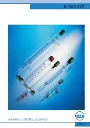
Trichter<br />
Funnels
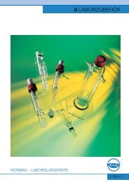
Laborzubehör<br />
Laboratory Accessory
Mess- und Regeltechnik<br />
Measurement and Control
Beispiele <strong>Komponente</strong>n<br />
Examples of Components
Laborflanschverb<strong>in</strong>dung mit <strong>in</strong>tegrierter Filterplatte<br />
Laboratory flange connection with <strong>in</strong>tegrated filter disc
Laborflanschverb<strong>in</strong>dung mit <strong>in</strong>tegrierter Filterplatte<br />
Laboratory flange connection with <strong>in</strong>tegrated filter disc
Dosiertrichter für Flüssigkeiten<br />
Dos<strong>in</strong>g funnel for liquids<br />
Bodenablassventil mit PT100 Sensor<br />
Bottom outlet valve with Pt100-sensor
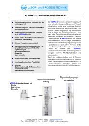
Glockenbodenkolonne<br />
Bubble cap tray column<br />
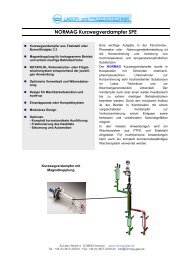
Universalverdampfer<br />
Circulat<strong>in</strong>g evaporator
Beispiele Apparaturen<br />
Examples of Apparatus
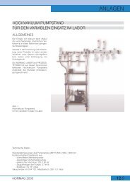
Vakuumpumpstand mit fettfreiem Vakuum-/Schutzgas Verteilerrechen<br />
Vacuum pump stand with grease-free vacuum/<strong>in</strong>ert gas distributor
Vakuum-/Schutzgas Verteilerrechen, fettfreie Ausführung<br />
Vacuum/<strong>in</strong>ert gas distributor, grease-free design
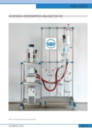
Rotafilm Kurzweg Verdampferanlage<br />
Rotafilm Short path evaporator unit
Fallfilm-Photoreaktor<br />
Fall<strong>in</strong>g film Photoreactor
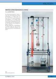
Mikrodrehbandkolonne<br />
Micro Sp<strong>in</strong>n<strong>in</strong>g band column
Beispiele <strong>Anlage</strong>n<br />
Examples of Units
Kont<strong>in</strong>uierliche Destillationsanlage<br />
Laboratory unit for cont<strong>in</strong>uous distillation
Destillationsanlage mit Fallfilmverdampfer<br />
Distillation unit with fall<strong>in</strong>g film evaporator
Fallfilm Verdampferanlage<br />
Fall<strong>in</strong>g film evaporator
Kurzweg Verdampferanlage<br />
Short path evaporator unit
Rührextraktion mit Extraktionsmittelrückgew<strong>in</strong>nung<br />
Extraction unit with extractant recovery
Ausbildungsanlage für Reaktion, Destillation, Filtration<br />
Tra<strong>in</strong><strong>in</strong>g unit for Reaction, Distillation, Filtration
Reaktionsanlage, Druckluftantrieb<br />
Reaction unit, with compressed-air drive
Reaktionsanlage Stahl/Emaille Kessel<br />
Reaction unit, steel/glass-l<strong>in</strong>ed vessel
Reaktorkaskade<br />
Reactor cascade
Mehrzweck-Reaktionsanlage<br />
Reaction unit, multi purpose
Löseapparatur für Edelmetalle, 200L<br />
Dissolv<strong>in</strong>g apparatus for noble metal, 200L
Löseapparatur für Edelemetall, 50L, mit Kipp-Senk-Vorrichtung<br />
Dissolv<strong>in</strong>g apparatus for noble metal, 50L, with tilt<strong>in</strong>g device
Löseapparatur für Edelmetalle<br />
Dissolv<strong>in</strong>g apparatus for noble metal
Misch-<strong>Anlage</strong>, <strong>Anlage</strong> <strong>zur</strong> Herstellung flüssiger Lösungen (Pharmazie)<br />
Unit for the production of liquid solvents (Pharmacy)
Reaktionsanlage für Lehrausbildung<br />
Reaction unit for tra<strong>in</strong><strong>in</strong>g
<strong>Komponente</strong>n für Apparate und <strong>Anlage</strong>n<br />
Components for Apparatus and units
Tech-Bauteile, SPF System, KF-System<br />
Tech-Components, SPF-System, KF-System
Rohrleitungen mit KF- und <strong>QVF</strong>-Flansch<br />
Pipel<strong>in</strong>e components with KF- and <strong>QVF</strong> flanges
R<strong>in</strong>gdichtungen aus PTFE KF- und <strong>QVF</strong>-Flansche<br />
Gaskets made of PTFE for KF- and <strong>QVF</strong> flanges
Faltenbälge, Gelenkdichtungen, Zwischenstücke<br />
Bellows, Flexible gaskets, Spacers
Gefäßhauben<br />
Vessel cover
Eckventil, System SPF<br />
Valve, 90°, System SPF
Durchgangsventil, System KF mit Positionsrückmeldung<br />
Valve, straight through, System KF with position <strong>in</strong>dicator
Pneumatisches Eckventil, System SPF<br />
Pneumatic Valve, 90°, System SPF
Pneumatisches Ventil mit Schließkontakt<br />
Pneumatic valve with A-contact
Pneumatisches Ventil mit Schließkontakt<br />
Pneumatic valve with A-contact
Pneumatisches Ventil mit Schließkontakt<br />
Pneumatic valve with A-contact
Kugelhahn mit pneumatischem Antrieb<br />
Pneumatically actuated ball valve
Wärmeüberträger<br />
Heat exchanger
Glockenbodenkolonnne<br />
Bubble cap tray column
Abschei<strong>der</strong> DN80<br />
Separator DN 80
Abschei<strong>der</strong> DN200<br />
Separator DN200
Abschei<strong>der</strong> DN300<br />
Separator DN300
Rührwerksantrieb elektrisch mit Ankerrührer,<br />
Design Standard- o<strong>der</strong> EX-Ausführung<br />
Electric Stirrer drive with anchor stirrer, Design Standard or EX
Rührwerksantrieb elektrisch mit Propellerrührer,<br />
Design Standard- o<strong>der</strong> EX-Ausführung<br />
Electric Stirrer drive with propeller stirrer, Design Standard or EX
Rohrbündel-Wärmetauscher<br />
Shell and tube heat exchanger
Rohrbündel-Wärmetauscher<br />
Shell and tube heat exchanger
Rohrbündel-Wärmetauscher<br />
Shell and tube heat exchanger
Rohrbündel-Wärmetauscher<br />
Shell and tube heat exchanger
<strong>Kompetenz</strong> <strong>in</strong> <strong>Glas</strong><br />
Reaktion • Destillation • Absorbtion • Filtration • Extraktion<br />
NORMAG Labor- und Prozesstechnik GmbH<br />
Auf dem Ste<strong>in</strong>e 4 • 98693 Ilmenau/Germany<br />
Tel.: +49 3677 / 2079-0 • Fax: +49 3677 / 2079-20<br />
Email: <strong>in</strong>fo@normag-glas.de<br />
www.normag-glas.de