BLZ400 BLZNI400 - HEB Hydraulik - Elementebau GmbH
BLZ400 BLZNI400 - HEB Hydraulik - Elementebau GmbH
BLZ400 BLZNI400 - HEB Hydraulik - Elementebau GmbH

Erfolgreiche ePaper selbst erstellen
Machen Sie aus Ihren PDF Publikationen ein blätterbares Flipbook mit unserer einzigartigen Google optimierten e-Paper Software.
<strong>BLZ400</strong>-3-2011<br />
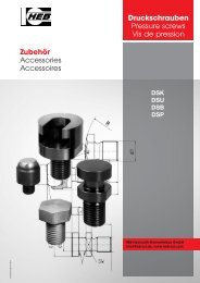
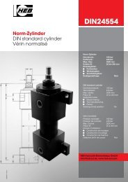
<strong>Hydraulik</strong>-Blockzylinder<br />
Block cylinders<br />
Vérins blocs<br />
<strong>BLZ400</strong><br />
<strong>BLZNI400</strong><br />
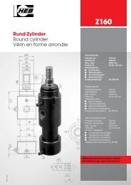
Block-Zylinder<br />
Nenndruck: 400 bar<br />
Prüfdruck: 600 bar<br />
Max. Hub: 500 mm<br />
Kolben Ø: 16 bis 100 mm<br />
Einsatzgebiet:<br />
• Formenbau<br />
• Werkzeugbau<br />
• Vorrichtungsbau<br />
Endlagenabfrage: als <strong>BLZNI400</strong><br />
Block cylinder<br />
Nominal pressure: 400 bar<br />
Test pressure: 600 bar<br />
Max. stroke: 500 mm<br />
Piston Ø: 16 to 100 mm<br />
Application area:<br />
• Mould-making<br />
• Tool manufacturing<br />
• Fixture<br />
Sensing of end position: as <strong>BLZNI400</strong><br />
Vérin bloc<br />
Pression nominale: 400 bar<br />
Pression de contrôle: 600 bar<br />
Max. Course: 500 mm<br />
Piston Ø: 16 à 100 mm<br />
Domain d’utilisation:<br />
• Construction de moulages<br />
• Construction d’outillage<br />
• Construction de fixations<br />
Détection de fin de course: en <strong>BLZNI400</strong><br />
<strong>HEB</strong> <strong>Hydraulik</strong>-<strong>Elementebau</strong> <strong>GmbH</strong><br />
info@heb-zyl.de, www.heb-zyl.com
Allgemeine Beschreibung<br />
und Hinweise<br />
•<br />
•<br />
•<br />
•<br />
•<br />
•<br />
•<br />
•<br />
•<br />
•<br />
•<br />
•<br />
2<br />
Blockbauweise, extrem kleine<br />
Baulängen, vorzugsweise für<br />
kurze Hübe geeignet.<br />
Bauformen gemäß Übersicht<br />
Seite 6 und 7.<br />
Lieferbare Funktionsarten Seite 3.<br />
Hübe nach Kundenwunsch,<br />
Standardhübe in den Bauformen<br />
1 - 2 - 3 siehe Seite 4 (kurzfristig<br />
lieferbar). Hubtoleranz nach<br />
DIN/ISO 2768m.<br />
Hubbegrenzung durch vordere<br />
und hintere Anschlagfläche, bei<br />
Kolbengeschwindigkeiten über<br />
0,1 m/sec. ist mechanische<br />
Hubbegrenzung oder Endlagendämpfung<br />
zu empfehlen.<br />
Dämpfungslänge Seite 23.<br />
Die eingebauten Dichtungen sind<br />
für Hydroflüssigkeiten H, HL, HLP<br />
nach DIN 51524/51525 und den<br />
Temperaturbereich von -20° C bis<br />
+90° C geeignet. Bei höheren<br />
Tem peraturen und anderen<br />
Druck medien können entsprechende<br />
Dichtungswerkstoffe eingesetzt<br />
werden.<br />
(Absprache erforderlich.)<br />
Betriebsdruck – Nenndruck max.<br />
400 bar.<br />
Kolben ø 16 bis 100 mm nach<br />
DIN/ISO 3320.<br />
Kolbenstangenlauffläche hartverchromt,<br />
geschliffen und poliert,<br />
serienmäßige Ausrüstung mit<br />
Staubabstreifer, Stangenende<br />
mit Innengewinde.<br />
Kolbenstangendichtung –<br />
PU-Nutring.<br />
Kolbendichtung – PTFE – Gleitring<br />
(statisch nicht dicht).<br />
General description and<br />
informations<br />
Bloc by bloc extremely small construction<br />
lengths, preferably appropriate<br />
to short strokes.<br />
Construction forms according to the<br />
summary page 6 and 7.<br />
Deliverable modes of operation<br />
page 3.<br />
Strokes according to the wishes of<br />
the customers standard strokes with<br />
the construction forms 1-2-3 see<br />
page 4 (deliverable at short notice).<br />
Stroke tolerance according to German<br />
Standard DIN/ISO 2768m.<br />
Stroke limitation through the front<br />
and back stop face, for piston<br />
speeds exceeding 0,1 m/sec we<br />
recommend a mechanical stroke<br />
limitation or a cushioning.<br />
Length of damping page 23.<br />
The installed seals are suitable to<br />
hydraulic fluids H, HL, HLP according<br />
to German Standard DIN 51524/<br />
51525 and to temperatures from -<br />
20°C to +90° C. With higher temperatures<br />
and other pressure mediums<br />
appropriate sealing material can be<br />
used. (Arrangement necessary.)<br />
Operating pressure – nominal pressure<br />
maxim. 400 bar.<br />
Piston ø 16 to 100 mm according to<br />
DIN 3320.<br />
Piston-rods hard-chrome plated,<br />
ground and polished, standard<br />
equipement with dust scraper,<br />
piston-rod end with internal thread.<br />
Piston-rod seal – PU/groove ring.<br />
Piston seal – PTFE – axial face seal<br />
(no static sealing effect).<br />
Description générale et des<br />
informations<br />
Bloc à bloc des mesures de construction<br />
extrêmement petites, de<br />
préférence appropriées aux courses<br />
courtes.<br />
Modes de construction selon l’aperçu<br />
page 6 et 7.<br />
Modes de fonctionnement livrables<br />
page 3.<br />
Courses selon le désir du client, des<br />
courses standard pour les modes de<br />
construction 1 - 2 - 3 voir page 4<br />
(livrables à court terme). Tolérance<br />
de course selon DIN/ISO 2768m.<br />
Limitation de course par surface<br />
d’arrêt de devant et de derrière, pour<br />
des vitesses de piston plus de 0,1<br />
m/sec. nous recommandons une<br />
limitation de course mécanique ou<br />
amortissement de la fin de course.<br />
Longueur de l’amortissement page 23.<br />
Les garnitures installées sont appropriées<br />
pour des liquides hydrauliques<br />
H, HL, HLP selon DIN 51524/51525<br />
et pour des températures de -20° C<br />
a +90° C. Pour des températures<br />
supérieures et d’autres médias de<br />
pression on peut utiliser des matières<br />
de garniture conformes.<br />
(Accord nécessaire.)<br />
Pression de fonctionnement – pression<br />
nominale maxim. 400 bar.<br />
ø piston 16 jusqu’ à 100 mm selon<br />
DIN 3320.<br />
Tiges de piston chromées durement,<br />
meulées et polies, équipement standard<br />
avec dépoussiéreur, fin de la<br />
tige de piston avec filet intérieur.<br />
Garniture de la tige de piston –<br />
PU/joint en U à lèvres.<br />
Garniture de piston – PTFE – anneau<br />
de glissement (sans effet hermétique).<br />
<strong>HEB</strong> <strong>Hydraulik</strong>-<strong>Elementebau</strong> <strong>GmbH</strong> / Tel. (0761) 13099-0, Fax (0761) 13 50 66<br />
<strong>BLZ400</strong>
Funktionsarten Modes of operation Modes de fonctionnement<br />
3<br />
200<br />
201<br />
206<br />
209<br />
211<br />
213<br />
214<br />
216<br />
218<br />
219<br />
Sinnbild nach DIN-ISO 1219/1 • Symbol according to DIN-ISO 1219/1 •<br />
Symbole selon DIN-ISO 1219/1<br />
Bezeichnung • Order specification • Référence de commande<br />
Beschreibung Description<br />
Einfachwirkend stoßend<br />
Einfachwirkend ziehend<br />
Doppeltwirkend<br />
Doppeltwirkend, Endlagendämpfung<br />
beidseitig –<br />
nicht regelbar<br />
Doppeltwirkend, Endlagendämpfung<br />
vorn –<br />
nicht regelbar<br />
Doppeltwirkend, Endlagendämpfung<br />
hinten –<br />
nicht regelbar<br />
Doppeltwirkend, durchgehende<br />
Kolbenstange<br />
Doppeltwirkend, durchgehende<br />
Kolbenstange, Endlagendämpfung<br />
beidseitig<br />
– nicht regelbar<br />
Doppeltwirkend, durchgehende<br />
Kolbenstange, Endlagendämpfung<br />
einseitig –<br />
nicht regelbar<br />
Doppeltwirkend, durchgehende<br />
Kolbenstange, Endlagendämpfung<br />
einseitig –<br />
nicht regelbar<br />
Simple-acting,<br />
pushing action<br />
Simple-acting,<br />
drawing action<br />
Double-acting<br />
Double-acting,<br />
cushioning on both<br />
sides – not adjustable<br />
Double-acting,<br />
cushioning in front –<br />
not adjustable<br />
Double-acting,<br />
cushioning in the rear –<br />
not adjustable<br />
Double-acting, doubleended<br />
piston-rod<br />
Double-acting, doubleended<br />
piston-rod<br />
cushioning on both sides<br />
–not adjustable<br />
Double-acting, doubleended<br />
piston-rod<br />
cushioning on one side<br />
– not adjustable<br />
Double-acting, doubleended<br />
piston-rod<br />
cushioning on one side<br />
– not adjustable<br />
e-mail: info@heb-zyl.de / homepage: http://www.heb-zyl.com<br />
Description<br />
A effet simple,<br />
poussant<br />
A effet simple, tirant<br />
A effet double<br />
A effet double, amortissement<br />
des deux côtés –<br />
ne pas adjustable<br />
A effet double, amortissement<br />
au front –<br />
ne pas adjustable<br />
A effet double, amortissement<br />
au dos –<br />
ne pas adjustable<br />
A effet double, tige<br />
de piston traversante<br />
A effet double, tige<br />
de piston traversante,<br />
amortissement des deux<br />
côtés –ne pas adjustable<br />
A effet double, tige<br />
de piston traversante,<br />
amortissement d’un côté<br />
– ne pas adjustable<br />
A effet double, tige<br />
de piston traversante,<br />
amortissement d’un côté<br />
– ne pas adjustable<br />
<strong>BLZ400</strong>
Technische Daten Technical data Caractéristiques techniques<br />
Kolben ∅<br />
Piston ∅<br />
∅ piston<br />
16 20 25 32 40 50 63 80 100<br />
Kolbenstangen ∅<br />
Piston-rod ∅<br />
∅ tige de piston<br />
10 12 16 20 25 32 40 50 60<br />
Kolbenfläche (stoßend) (AK ) cm2 Piston face (pushing)<br />
de piston (poussante)<br />
2.01 3.14 4.91 8.04 12.56 19.63 31.16 50.24 78.50<br />
Kolbenringfläche (ziehend) (AR ) cm2 Piston ring face (drawing action)<br />
Surface du segment de piston (tirant)<br />
1.22 2.00 2.90 4.90 7.65 11.59 18.60 30.61 50.24<br />
Kraft (AK ) daN 100 bar 201 314 491 804 1256 1963 3116 5024 7850<br />
Force 150 bar 301 471 736 1206 1884 2944 4674 7536 11775<br />
Force 200 bar 402 628 982 1608 2512 3926 6232 10048 15700<br />
300 bar 603 942 1473 2412 3768 5889 9348 15072 23550<br />
400 bar 804 1256 1964 3216 5024 7852 12464 20096 31400<br />
Kraft (AR ) daN 100 bar 122 200 290 490 765 1159 1860 3061 5024<br />
Force 150 bar 183 300 439 735 1147 1738 2790 4591 7536<br />
Force 200 bar 244 400 580 980 1530 2318 3720 6122 10048<br />
300 bar 366 600 870 1470 2295 3477 5580 9183 15072<br />
400 bar 488 800 1160 1960 3060 4636 7440 12244 20096<br />
Standardhübe BLZ 400 Funktionsart „206“<br />
Standard strokes mode of operation „206“<br />
Courses standardisées mode de fonctionnement „206“<br />
Kolben ∅ mm<br />
piston ∅ 16 20 25 32 40 50 63<br />
∅ piston<br />
Hübe – mm 15 ● ● ● ● ● ●<br />
Strokes 20 ● ● ● ● ● ● ●<br />
Courses 25 ● ● ● ● ● ● ●<br />
30 ● ● ● ● ● ● ●<br />
40 ● ● ● ● ● ● ●<br />
50 ● ● ● ● ● ●<br />
60 ● ● ● ● ● ●<br />
70 ●<br />
80 ● ● ● ●<br />
100 ● ● ● ● ●<br />
4<br />
<strong>HEB</strong> <strong>Hydraulik</strong>-<strong>Elementebau</strong> <strong>GmbH</strong> / Tel. (0761) 13099-0, Fax (0761) 13 50 66<br />
<strong>BLZ400</strong>
<strong>BLZ400</strong><br />
Sonderausstattungen Special equipments Équipements optionnels<br />
• Hochhitzebeständige Dichtungen für Hydroflüssigkeiten der Typen H, HL, HLP – DIN 51524/51525<br />
und Temperaturen ab +100° C bis +200° C.<br />
High heat-resistant seals for hydraulic fluids type H, HL, HLP – German Standard DIN 51524/51525<br />
and for temperatures from +100° C up to +200° C.<br />
Garnitures réstistantes aux températures très élevées pour liquides type H, HL, HLP – DIN 51524/51525<br />
et des températures de +100° C jusqu’ à +200°C.<br />
• Beidseitige Entlüftungsschrauben für Schlauchanschluß<br />
On both sides venting screws for flexible tube connection /<br />
Sur le deux côtés vis de sortie d’air pour raccord de tuyau<br />
• Kolbenstangenlauffläche gehärtet und hartverchromt<br />
Piston-rods hardened and hard-chrome plated /<br />
Tiges de piston trempées et chromée durement<br />
• Kolben statisch dicht – ab 20 mm Kolben Ø lieferbar<br />
Piston with static sealing effect – available for piston diameters above 20mm<br />
Piston avec effet hermétique – livrable avec des pistons Ø à 20 mm et plus<br />
• Näherungsschalter BES-S für Temperaturen bis +120°C.<br />
Proximity sensor BES-S for temperatures up to +120°C /<br />
Détecteur de proximité BES-S pour des températures jusqu’ à +120°C<br />
• Stangenseitiger Zentrierbund Rod-side with centering collar Côté tige avec collet de centrage<br />
• Nut zur Justierung des <strong>Hydraulik</strong>-Zylinders standard N4-N2 nach Kundenwunsch<br />
Groove for adjustment standard N4-N2 wishes of the customers<br />
Rainure pour ajustement standard N4-N2 désir du client<br />
• Kolbenstangenende mit Außengewinde<br />
Piston-rod end with external thread<br />
Fin de la tige de piston avec filet extérieur<br />
S 5<br />
S 7<br />
S 13<br />
S 35<br />
S 120<br />
ZE<br />
N4.1-N2.1<br />
B1-B2<br />
Die Maße zu Kolbenstangenende B1-B2 und M1-M2 können nach Kundenwunsch geändert werden. Unter der Zusatz bezeichnung<br />
B1.1-B2.1 bei Angabe der Maßeinheiten L8, L7, d5 oder unter der Bezeichnung M1.1-M2.1 bei Angabe der Maßeinheiten L3, L15, d1.<br />
The dimensions B1-B2 and M1-M2 to the end of piston rod can be changed on request. Use the additional code B1.1-B2.1 and give the<br />
dimensions L8, L7 and d5, or the additional code M1.1-M2.1 and give L3, L15, d1.<br />
Les dimensions jusqu’à la fin de la tige du piston B1-B2 et M1-M2 sont modifiables à la demande du client, indiquer B1.1-B2.1 pour les<br />
dimensions L8, L7 et d5, ou M1.1-M2.1 pour les dimensions L3, L15 et d1.<br />
Zentrierbund „ZE“<br />
centering collar<br />
collet de centrage<br />
Kolbenstangenende mit Außengewinde<br />
„B1“/„B2“<br />
Piston-rod end with external thread.<br />
Fin de la tige de piston avec filet<br />
extérieur.<br />
Nut „N4-N2“/„N4.1-N2.1“<br />
Groove<br />
Rainure<br />
Kolben ∅ mm • Piston ∅ • ∅ tige de piston 16 20 25 32 40 50 63 80 100<br />
d 10 f7 nicht Bauform 7 + 7.1<br />
except construction form 7 + 7.1 36 38 46 52 60 72 94 115 150<br />
à l’exception du mode de construction 7 + 7.1<br />
d 11 f7 nur Bauform 7 + 7.1<br />
only construction form 7 + 7.1 30 30 38 42 48 62 82 90 125<br />
seulement mode de construction 7 + 7.1<br />
L 20 2 2 2 3 3 3 3 4 4<br />
d 5 M6 M8 M10 M 12 M 16 M 20 M 27 M 30 M 42<br />
L 7 12 16 20 22 25 35 50 55 65<br />
L 8 19 23 30 34 40 52 68 75 87<br />
b N9 8 8 10 12 12 14 20 22 28<br />
t 2 2 2 3 3 5 5 7 7<br />
h nach Index L2 (BLZ 400 - Seite 8/9) oder L23 (BLZ NI 400 - Seite 8/9) oder nach Kundenwunsch.<br />
according index L2 (BLZ 400 - page 8/9) or L23 (BLZ 400 NI - page 8/9) or according to the wishes of customers.<br />
selon index L2 (BLZ 400 - page 8/9) ou L23 (BLZ 400 NI - page 8/9) ou selon le désir du client.<br />
e-mail: info@heb-zyl.de / homepage: http://www.heb-zyl.com 5
Übersicht der lieferbaren Summary of the deliverable Apercu sur les modes de<br />
Bauformen construction forms construction livrables<br />
Details ab Seite 8<br />
details from page 8<br />
Détails à partir de la page 8<br />
6<br />
1.1 1.2<br />
Bezeichnung<br />
Order specification<br />
Référence de<br />
commande<br />
1<br />
Seite / page 8/9<br />
1.1<br />
1.2<br />
Seite / page 8/9<br />
2<br />
Seite / page 10/11<br />
2.1<br />
Seite / page 10/11<br />
3<br />
Seite / page 12/13<br />
3.1<br />
Seite / page 12/13<br />
4.1<br />
Seite / page 14/15<br />
Beschreibung<br />
Description<br />
Description<br />
2 Querbohrungen, ab 160 bar ist Abstützung erforderlich<br />
2 cross holes, from 160 bar a support is necessary<br />
2 forures transversales, à partir de 160 bar un support est nécessaire<br />
2 Gewindebohrungen, ab 160 bar ist Abstützung erforderlich<br />
2 thread borings, from 160 bar a support is necessary<br />
2 alésages filetés, à partir de 160 bar un support est nécessaire<br />
4 Längsbohrungen, kolbenseitig mit Senkung für DIN EN ISO 4762<br />
4 longitudinal holes, piston-side with counterbore for DIN EN ISO 4762<br />
4 forures longitudinales, côté piston avec noyure pour DIN EN ISO 4762<br />
4 Gewindebohrungen stangenseitig<br />
4 thread borings, rod-side<br />
4 alésages filetés, côté tige<br />
4 Längsbohrungen, stangenseitig mit Senkung für DIN EN ISO 4762<br />
4 longitudinal holes, rod-side with counterbore for DIN EN ISO 4762<br />
4 forures longitudinales, côté tige avec noyure pour DIN EN ISO 4762<br />
4 Gewindebohrungen kolbenseitig<br />
4 thread borings, piston-side<br />
4 alésages filetés, côté piston<br />
4 Durchgangsbohrungen, Anschlüsse auf der Schmalseite mit<br />
Senkung für O-Ring-Abdichtung zum Anflanschen an Verteilerplatte<br />
(Abstützung erforderlich)<br />
4 through holes, connections at the small side with lowering for o-ring<br />
seal for the flanging at the distribution plate (support necessary)<br />
4 alésages de passage, raccords à la côté étroite avec abaissement<br />
pour joint torique pour brider à la table de distribution<br />
(support necéssaire)<br />
<strong>HEB</strong> <strong>Hydraulik</strong>-<strong>Elementebau</strong> <strong>GmbH</strong> / Tel. (0761) 13099-0, Fax (0761) 13 50 66<br />
<strong>BLZ400</strong>
<strong>BLZ400</strong><br />
Übersicht der lieferbaren Summary of the deliverable Apercu sur les modes de<br />
Bauformen construction forms construction livrables<br />
Details ab Seite 8<br />
details from page 8<br />
Détails à partir de la page 8<br />
X<br />
X<br />
X<br />
X<br />
Bezeichnung<br />
Order specification<br />
Référence de<br />
commande<br />
5.1<br />
Seite / page 16/17<br />
6<br />
Seite / page 18/19<br />
6.1<br />
Seite / page 18/19<br />
7<br />
Seite / page 20/21<br />
7.1<br />
Seite / page 20/21<br />
8<br />
Seite / page 22/23<br />
8.1<br />
Seite / page 22/23<br />
Beschreibung<br />
Description<br />
Description<br />
4 Gewindebohrungen, Anschlüsse auf der Schmalseite mit Senkung<br />
für O-Ring-Abdichtung zum Anflanschen an Verteilerplatte<br />
(Abstützung erforderlich)<br />
4 thread borings, connections at the small side with lowering for o-ring<br />
seal for the flanging at the distribution plate (support necessary)<br />
4 alésages filetés, raccords à la côté étroite avec abaissement pour<br />
joint torique pour brider à la table de distribution (support necéssaire)<br />
4 Durchgangsbohrungen, Anschlüsse auf der Breitseite mit Senkung<br />
für O-Ring-Abdichtung zum Anflanschen an Verteilerplatte<br />
4 through holes, connections at the broadside with lowering for o-ring<br />
seal for the flanging at the distribution plate<br />
4 alésages de passage, raccords à la côté large avec abaissement<br />
pour joint torique pour brider à la table de distribution<br />
4 Gewindebohrungen, Anschlüsse auf der Breitseite mit Senkung<br />
für O-Ring-Abdichtung zum Anflanschen an Verteilerplatte<br />
4 thread borings, connections at the broadside with lowering for o-ring<br />
seal for the flanging at the distribution plate<br />
4 alésages filetés, raccords à la côté large avec abaissement pour joint<br />
torique pour brider à la table de distribution<br />
4 Axialbohrungen, Anschlüsse stangenseitig mit Senkung für<br />
O-Ring-Abdichtung zum Anflanschen an Verteilerplatte<br />
4 axial borings, connections rod-side with lowering for o-ring seal for<br />
the flanging at the distribution plate<br />
4 forures axiales, raccords à la côté tige avec abaissement pour joint<br />
torique pour brider à la table de distribution<br />
4 Gewindebohrungen, Anschlüsse stangenseitig mit Senkung für<br />
O-Ring-Abdichtung zum Anflanschen an Verteilerplatte<br />
4 thread borings, connections rod-side with lowering for o-ring seal for<br />
the flanging at the distribution plate<br />
4 alésages filetés, raccords à la côté tige avec abaissement pour joint<br />
torique pour brider à la table de distribution<br />
4 Axialbohrungen, Anschlüsse bodenseitig mit Senkung für<br />
O-Ring-Abdichtung zum Anflanschen an Verteilerplatte<br />
4 axial borings, connections bottom side with lowering for o-ring seal<br />
for the flanging at the distribution plate<br />
4 forures axiales, raccords côté fond avec abaissement pour joint<br />
torique pour brider à la table de distribution<br />
4 Gewindebohrungen, Anschlüsse bodenseitig mit Senkung für<br />
O-Ring-Abdichtung zum Anflanschen an Verteilerplatte<br />
4 thread borings, connections bottom side with lowering for o-ring<br />
seal for the flanging at the distribution plate<br />
4 forures axiales, raccords côté fond avec abaissement pour joint<br />
torique pour brider à la table de distribution<br />
e-mail: info@heb-zyl.de / homepage: http://www.heb-zyl.com 7
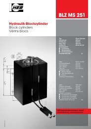
Bauform 1/1.1/1.2 Construction form 1/1.1/1.2 Mode de construction 1/1.1/1.2<br />
BLZ 400<br />
BLZ 400 DK<br />
BLZ NI 400<br />
BLZ NI 400 DK<br />
8<br />
M1<br />
wie BLZ 400,<br />
mit durchgehender Kolbenstange<br />
with through-going piston rod<br />
avec tige de piston continu<br />
mit integrierten Näherungsschaltern<br />
with integrated proximity sensors<br />
avec détecteurs de proximité intégrés<br />
wie BLZ NI 400,<br />
mit durchgehender Kolbenstange<br />
with through-going piston rod<br />
avec tige de piston continu<br />
M1 M2<br />
/ stroke / course<br />
Bauform 1<br />
Construction form<br />
Mode de construction<br />
<strong>HEB</strong> <strong>Hydraulik</strong>-<strong>Elementebau</strong> <strong>GmbH</strong> / Tel. (0761) 13099-0, Fax (0761) 13 50 66<br />
➃<br />
➃<br />
➃<br />
➃<br />
➀<br />
➀<br />
➀<br />
➂<br />
➀<br />
➂<br />
➂<br />
➂<br />
➁<br />
➁<br />
➁<br />
Zylinderseite - page ➀. . .➃<br />
➁<br />
Bauform 1.1 Bauform 1.2<br />
Detaillierte Beschreibung der Schalter: Seite 24 + 25<br />
Detailed description of the proximity sensors see page 24 + 25<br />
Description des détecteurs de proximité intégrés voir page 24 + 25<br />
Detaillierte Beschreibung der Schalter: Seite 24 + 25<br />
Detailed description of the proximity sensors see page 24 + 25<br />
Description des détecteurs de proximité intégrés voir page 24 + 25<br />
<strong>BLZ400</strong>
<strong>BLZ400</strong><br />
Bauform 1/1.1/1.2 Construction form 1/1.1/1.2 Mode de construction 1/1.1/1.2<br />
Kolben ∅ / Piston ∅ / ∅ piston 16 20 25 32 40 50 63 80 100<br />
d2 Stangen ∅ / Piston rod ∅ / ∅ tige de piston 10 12 16 20 25 32 40 50 60<br />
A Anschluß / Connection / Raccord G 1/4 G 1/4 G 1/4 G 1/4 G 1/4 G 1/4 G 1/2 G 1/2 G 1/2<br />
b2 35 40 45 55 63 75 95 120 150<br />
b3 40 40 50 55 63 76 95 120 158<br />
b4 60 60 65 75 85 100 125 160 200<br />
b7 ca. 56 57 60 63 65 71 78 99 109<br />
b8 70 75 75 80 85 100 125 160 200<br />
d1 M6 M8 M10 M12 M16 M20 M27 M30 M42<br />
d3 6,5 6,5 8,5 10,5 10,5 13 17 21 25<br />
d8 9,5 11,5 15 19 24 31 39 49 59<br />
L0 * (+ Hub) bei den Funktionsarten<br />
(+ stroke) with the modes of operation<br />
(+ course) pour les modes de<br />
fonctionnement<br />
200 / 201/ 206 1) 41 45 44 50 54 65 72 85 90<br />
209 94 95 97 105 119 140 156 163<br />
211 61 61 64 70 81 96 109 116<br />
213 78 78 83 89 104 117 133 137<br />
L01 * „ 200 / 201/ 206 2) 69 68 66,5 70 75 89 94 105 111<br />
209 2) 118 122 122 132 149 167 186 192<br />
211 2) 85 86 89 95 107 119 134 141<br />
213 2) 102 104 107 114 132 142 159 165<br />
L02 „ 214 3) 58 62 61 68,5 73 88 93 109 111<br />
216 94 95 97 105 119 140 156 163<br />
218 / 219 78 78 83 89 104 117 133 137<br />
L03 „ 214 4) 86 86 85 91 98 114 119 131 135<br />
216 4) 118 122 122 132 149 167 186 192<br />
218 / 219 4) 102 104 107 114 132 142 159 165<br />
L2 30 30 33 38 40 44 50 60 64<br />
L3 18 19 25 28 35 30 40 40 60<br />
L5 16,5 17 18 22 24 27 26 34 35<br />
L6 bei den Funktionsarten<br />
with the modes of operation<br />
pour les modes de fonctionnement<br />
200 / 201/ 206 11 11 11 11 11 13 17 21 25<br />
211 11 11 11 11 13 17 21 25<br />
209 / 213 17 18 22 24 27 26 34 35<br />
L15 7 7 10 12 15 17 18 20 22<br />
L16 „ 200 / 201/ 206 / 214 28 29 29,5 32 34 40 40 47 49<br />
213 / 219 29 29,5 32 34 40 40 47 49<br />
209 / 211 / 216 / 218 45 47 46 51 57 65 73 76<br />
L17 „ 200 / 201/ 206 11 11 11 11 11 15 15 21 25<br />
211 11 11 11 11 15 15 21 25<br />
209 / 213 45 47 46 51 57 65 73 76<br />
L19 ist hubabhängig und erst ab Hub (Q) in dieser Länge lieferbar... 18 19 25 28 35 30 40 40 60<br />
L19 depends on the stroke and only from stroke (Q) it is L 19 est dépendant de la course et seulement livrable avec<br />
available with this length . . . cette longueur à partir de la course (Q) . . .<br />
Hub Q - stroke Q - course Q 214 / 218 18 19 28 27 41 32 49 47 70<br />
216 / 219 3 11 13 25 17 26 24 44<br />
L21 „ 214 28 29 29,5 32 34 40 40 47 49<br />
218 29 29,5 32 34 40 40 47 49<br />
216 / 219 45 47 46 51 57 65 73 76<br />
L23 „ 206 / 214 40 41 44 47 49 58 59 68 73<br />
213 / 219 41 44 47 49 58 59 68 73<br />
209 / 211 / 216 / 218 59 61 62 67 74 85 95 101<br />
L24 12 12 16 20 20 24 32 40 48<br />
m3 M6 M6 M8 M10 M10 M12 M16 M20 M24<br />
* Die Längenmaße sind gültig bei Hüben bis max. . . mm. 60 100 120 150 150 150 170 200 200<br />
Bei längeren Hüben bitte anfragen.<br />
The measures of length are valid with strokes up to maxim. . . mm. Les mesures de longueur sont valables pour les courses jusqu’ a<br />
In case of longer strokes please consult us. maxim. ... mm. Veuillez demander pour les courses plus longues.<br />
1) 2) 3) 4) Zur Festlegung der Längen L0, L01, L02, L03 müssen<br />
aufgeführte Mindesthubzuschläge berücksichtigt werden –<br />
Kleinere Hübe durch Einbau einer Hubbegrenzung möglich.<br />
1) 2) 3) 4) To determine the lengths L0, L01, L02, and L03, the<br />
minimum stroke constants given must be added.<br />
Shorter strokes can be obtained by installing spacers.<br />
1) 15 15 15 15 15 15 20 25 30<br />
2) 0 0 4 5 4 0 6 10 15<br />
3) 2 0 5 8 7 0 7 11 17<br />
4) 0 0 3 3 0 2 0 5 11<br />
1) 2) 3) 4) pour déterminer les longueurs L0, L01, L02, L03,<br />
tenir compte des surlongueurs de course.<br />
Possibilité de courses plus courtes par montage d’un limiteur de course.<br />
e-mail: info@heb-zyl.de / homepage: http://www.heb-zyl.com 9
Bauform 2/2.1 Construction form 2/2.1 Mode de construction 2/2.1<br />
BLZ 400<br />
BLZ 400 DK<br />
wie BLZ 400,<br />
mit durchgehender Kolbenstange<br />
with through-going piston rod<br />
avec tige de piston continu<br />
BLZ NI 400<br />
10<br />
M1<br />
mit integrierten Näherungsschaltern<br />
with integrated proximity sensors<br />
avec détecteurs de proximité intégrés<br />
BLZ NI 400 DK<br />
wie BLZ NI 400,<br />
mit durchgehender Kolbenstange<br />
with through-going piston rod<br />
avec tige de piston continu<br />
(2.1) (2)<br />
M1 M2<br />
Senkung für<br />
DIN EN ISO 4762<br />
Counterbore for . . .<br />
noyure pour . . .<br />
/ stroke<br />
/ course<br />
Bauform 2<br />
Construction form<br />
Mode de construction<br />
<strong>HEB</strong> <strong>Hydraulik</strong>-<strong>Elementebau</strong> <strong>GmbH</strong> / Tel. (0761) 13099-0, Fax (0761) 13 50 66<br />
➃<br />
➃<br />
➃<br />
➃<br />
➂<br />
➀<br />
➀<br />
➀<br />
➀<br />
➂<br />
➂<br />
➂<br />
➁<br />
➁<br />
Zylinderseite - page ➀. . .➃<br />
➁<br />
➁<br />
Bauform 2.1<br />
Construction form<br />
Mode de construction<br />
Detaillierte Beschreibung der Schalter: Seite 24 + 25<br />
Detailed description of the proximity sensors see page 24 + 25<br />
Description des détecteurs de proximité intégrés voir page 24 + 25<br />
Detaillierte Beschreibung der Schalter: Seite 24 + 25<br />
Detailed description of the proximity sensors see page 24 + 25<br />
Description des détecteurs de proximité intégrés voir page 24 + 25<br />
<strong>BLZ400</strong>
<strong>BLZ400</strong><br />
Bauform 2/2.1 Construction form 2/2.1 Mode de construction 2/2.1<br />
Kolben ∅ / Piston ∅ / ∅ piston 16 20 25 32 40 50 63 80 100<br />
d2 Stangen ∅ / Piston rod ∅ / ∅ tige de piston 10 12 16 20 25 32 40 50 60<br />
A Anschluß / Connection / Raccord G 1/4 G 1/4 G 1/4 G 1/4 G 1/4 G 1/4 G 1/2 G 1/2 G 1/2<br />
b1 22 25 30 35 40 45 65 80 108<br />
b2 35 40 45 55 63 75 95 120 150<br />
b3 40 40 50 55 63 76 95 120 158<br />
b4 60 60 65 75 85 100 125 160 200<br />
b7 ca. 56 57 60 63 65 71 78 99 109<br />
b8 70 75 75 80 85 100 125 160 200<br />
d1 M6 M8 M10 M12 M16 M20 M27 M30 M42<br />
d4 6,5 6,5 8,5 10,5 10,5 13 17 21 25<br />
d8 9,5 11,5 15 19 24 31 39 49 59<br />
L0 * (+ Hub) bei den Funktionsarten<br />
(+ stroke) with the modes of operation<br />
(+ course) pour les modes de<br />
fonctionnement<br />
200 / 201/ 206 1) 41 45 44 50 54 65 72 85 90<br />
209 94 95 97 105 119 140 156 163<br />
211 61 61 64 70 81 96 109 116<br />
213 78 78 83 89 104 117 133 137<br />
L01 * „ 200 / 201/ 206 69 68 66,5 70 75 89 94 105 111<br />
209 118 122 122 132 149 167 186 192<br />
211 85 86 89 95 107 119 134 141<br />
213 102 104 107 114 132 142 159 165<br />
L02 „ 214 58 62 61 68,5 73 88 93 109 111<br />
216 94 95 97 105 119 140 156 163<br />
218 / 219 78 78 83 89 104 117 133 137<br />
L03 „ 214 86 86 85 91 98 114 119 131 135<br />
216 118 122 122 132 149 167 186 192<br />
218 / 219 102 104 107 114 132 142 159 165<br />
L3 18 19 25 28 35 30 40 40 60<br />
L5 16,5 17 18 22 24 27 26 34 35<br />
L6 bei den Funktionsarten<br />
with the modes of operation<br />
pour les modes de fonctionnement<br />
200 / 201/ 206 11 11 11 11 11 13 17 21 25<br />
211 11 11 11 11 13 17 21 25<br />
209 / 213 17 18 22 24 27 26 34 35<br />
L15 7 7 10 12 15 17 18 20 22<br />
L16 „ 200 / 201/ 206 /214 28 29 29,5 32 34 40 40 47 49<br />
213 / 219 29 29,5 32 34 40 40 47 49<br />
209 / 211 / 216 / 218 45 47 46 51 57 65 73 76<br />
L17 „ 200 / 201/ 206 11 11 11 11 11 15 15 21 25<br />
211 11 11 11 11 15 15 21 25<br />
209 / 213 45 47 46 51 57 65 73 76<br />
L19 ist hubabhängig und erst ab Hub (Q) in dieser Länge lieferbar ... 18 19 25 28 35 30 40 40 60<br />
L19 depends on the stroke and only from stroke (Q) it is L 19 est dépendant de la course et seulement livrable avec<br />
available with this length . . . cette longueur à partir de la course (Q) . . .<br />
Hub Q - stroke Q - course Q 214/218 18 19 28 27 41 32 49 47 70<br />
216 / 219 3 11 13 25 17 26 24 44<br />
L21 „ 214 28 29 29,5 32 34 40 40 47 49<br />
218 29 29,5 32 34 40 40 47 49<br />
216 / 219 45 47 46 51 57 65 73 76<br />
L24 12 12 16 20 20 24 32 40 48<br />
m4 M6 M6 M8 M10 M10 M12 M16 M20 M24<br />
* Die Längenmaße sind gültig bei Hüben bis max. . . . mm. 60 100 120 150 150 150 170 200 200<br />
Bei längeren Hüben bitte anfragen.<br />
The measures of length are valid with strokes up to maxim. . . . mm. Les mesures de longueur sont valables pour les courses jusqu’ a<br />
In case of longer strokes please consult us. maxim. ... mm. Veuillez demander pour les courses plus longues.<br />
1) Zur Festlegung der Längen L0, müssen<br />
aufgeführte Mindesthubzuschläge berücksichtigt werden –<br />
Kleinere Hübe durch Einbau einer Hubbegrenzung möglich.<br />
1) To determine the lengths L0, the<br />
minimum stroke constants given must be added.<br />
Shorter strokes can be obtained by installing spacers.<br />
1) 15 15 15 15 15 15 20 25 30<br />
1) pour déterminer les longueurs L0, tenir compte des surlongueurs de course.<br />
Possibilité de courses plus courtes par montage d’un limiteur de course.<br />
e-mail: info@heb-zyl.de / homepage: http://www.heb-zyl.com 11
Bauform 3/3.1 Construction form 3/3.1 Mode de construction 3/3.1<br />
BLZ 400<br />
BLZ 400 DK<br />
12<br />
Senkung für DIN EN ISO 4762<br />
Counterbore for . . .<br />
noyure pour . . .<br />
M1<br />
wie BLZ 400,<br />
mit durchgehender Kolbenstange<br />
with through-going piston rod<br />
avec tige de piston continu<br />
BLZ NI 400<br />
mit integrierten Näherungsschaltern<br />
with integrated proximity sensors<br />
avec détecteurs de proximité intégrés<br />
BLZ NI 400 DK<br />
wie BLZ NI 400,<br />
mit durchgehender Kolbenstange<br />
with through-going piston rod<br />
avec tige de piston continu<br />
(3) (3.1) Bauform 3<br />
Construction form<br />
Mode de construction<br />
Zylinderseite - page ➀. . .➃<br />
M1 M2<br />
/ stroke<br />
/ course<br />
<strong>HEB</strong> <strong>Hydraulik</strong>-<strong>Elementebau</strong> <strong>GmbH</strong> / Tel. (0761) 13099-0, Fax (0761) 13 50 66<br />
➃<br />
➃<br />
➃<br />
➃<br />
➀<br />
➂<br />
➀<br />
➂<br />
➀<br />
➀<br />
➂<br />
➂<br />
➁<br />
➁<br />
➁<br />
➁<br />
Bauform 3.1<br />
Construction form<br />
Mode de construction<br />
Detaillierte Beschreibung der Schalter: Seite 24 + 25<br />
Detailed description of the proximity sensors see page 24 + 25<br />
Description des détecteurs de proximité intégrés voir page 24 + 25<br />
Detaillierte Beschreibung der Schalter: Seite 24 + 25<br />
Detailed description of the proximity sensors see page 24 + 25<br />
Description des détecteurs de proximité intégrés voir page 24 + 25<br />
<strong>BLZ400</strong>
<strong>BLZ400</strong><br />
Bauform 3/3.1 Construction form 3/3.1 Mode de construction 3/3.1<br />
Kolben ∅ / Piston ∅ / ∅ piston 16 20 25 32 40 50 63 80 100<br />
d2 Stangen ∅ / Piston rod ∅ / ∅ tige de piston 10 12 16 20 25 32 40 50 60<br />
A Anschluß / Connection / Raccord G 1/4 G 1/4 G 1/4 G 1/4 G 1/4 G 1/4 G 1/2 G 1/2 G 1/2<br />
b1 22 25 30 35 40 45 65 80 108<br />
b2 35 40 45 55 63 75 95 120 150<br />
b3 40 40 50 55 63 76 95 120 158<br />
b4 60 60 65 75 85 100 125 160 200<br />
b7 ca. 56 57 60 63 65 71 78 99 109<br />
b8 70 75 75 80 85 100 125 160 200<br />
d1 M6 M8 M10 M12 M16 M20 M27 M30 M42<br />
d4 6,5 6,5 8,5 10,5 10,5 13 17 21 25<br />
d8 9,5 11,5 15 19 24 31 39 49 59<br />
L0 * (+ Hub) bei den Funktionsarten<br />
(+ stroke) with the modes of operation<br />
(+ course) pour les modes de<br />
fonctionnement<br />
200 / 201/ 206 1) 41 45 44 50 54 65 72 85 90<br />
209 94 95 97 105 119 140 156 163<br />
211 61 61 64 70 81 96 109 116<br />
213 78 78 83 89 104 117 133 137<br />
L01 * „ 200 / 201/ 206 69 68 66,5 70 75 89 94 105 111<br />
209 118 122 122 132 149 167 186 192<br />
211 85 86 89 95 107 119 134 141<br />
213 102 104 107 114 132 142 159 165<br />
L02 „ 214 58 62 61 68,5 73 88 93 109 111<br />
216 94 95 97 105 119 140 156 163<br />
218 / 219 78 78 83 89 104 117 133 137<br />
L03 „ 214 86 86 85 91 98 114 119 131 135<br />
216 118 122 122 132 149 167 186 192<br />
218 / 219 102 104 107 114 132 142 159 165<br />
L3 18 19 25 28 35 30 40 40 60<br />
L5 16,5 17 18 22 24 27 26 34 35<br />
L6 bei den Funktionsarten<br />
with the modes of operation<br />
pour les modes de fonctionnement<br />
200 / 201/ 206 11 11 11 11 11 13 17 21 25<br />
211 11 11 11 11 13 17 21 25<br />
209 / 213 17 18 22 24 27 26 34 35<br />
L15 7 7 10 12 15 17 18 20 22<br />
L16 „ 200 / 201/ 206 /214 28 29 29,5 32 34 40 40 47 49<br />
213 / 219 29 29,5 32 34 40 40 47 49<br />
209 / 211 / 216 / 218 45 47 46 51 57 65 73 76<br />
L17 „ 200 / 201/ 206 11 11 11 11 11 15 15 21 25<br />
211 11 11 11 11 15 15 21 25<br />
209 / 213 45 47 46 51 57 65 73 76<br />
L19 ist hubabhängig und erst ab Hub (Q) in dieser Länge lieferbar ... 18 19 25 28 35 30 40 40 60<br />
L19 depends on the stroke and only from stroke (Q) it is L 19 est dépendant de la course et seulement livrable avec<br />
available with this length . . . cette longueur à partir de la course (Q) ...<br />
Hub Q - stroke Q - course Q 214/218 18 19 28 27 41 32 49 47 70<br />
216 / 219 3 11 13 25 17 26 24 44<br />
L21 „ 214 28 29 29,5 32 34 40 40 47 49<br />
218 29 29,5 32 34 40 40 47 49<br />
216 / 219 45 47 46 51 57 65 73 76<br />
L24 12 12 16 20 20 24 32 40 48<br />
m4 M6 M6 M8 M10 M10 M12 M16 M20 M24<br />
* Die Längenmaße sind gültig bei Hüben bis max. . . . mm. 60 100 120 150 150 150 170 200 200<br />
Bei längeren Hüben bitte anfragen.<br />
The measures of length are valid with strokes up to maxim. . . . mm. Les mesures de longueur sont valables pour les courses jusqu’ a<br />
In case of longer strokes please consult us. maxim. ... mm. Veuillez demander pour les courses plus longues.<br />
1) Zur Festlegung der Länge L0 müssen aufgeführte<br />
Mindesthubzuschläge berücksichtigt werden –<br />
Kleinere Hübe durch Einbau einer Hubbegrenzung möglich.<br />
1) To determine the length L0, the minimum stroke constants<br />
given must be added.<br />
Shorter strokes can be obtained by installing spacers.<br />
1) 15 15 15 15 15 15 20 25 30<br />
1) pour déterminer les longueur L0, tenir compte des surlongueurs de course.<br />
Possibilité de courses plus courtes par montage d’un limiteur de course.<br />
e-mail: info@heb-zyl.de / homepage: http://www.heb-zyl.com 13
Bauform 4.1 Construction form 4.1 Mode de construction 4.1<br />
BLZ 400<br />
BLZ 400 DK<br />
14<br />
M1<br />
wie BLZ 400,<br />
mit durchgehender Kolbenstange<br />
with through-going piston rod<br />
avec tige de piston continu<br />
BLZ NI 400<br />
mit integrierten Näherungsschaltern<br />
with integrated proximity sensors<br />
avec détecteurs de proximité intégrés<br />
BLZ NI 400 DK<br />
wie BLZ NI 400,<br />
mit durchgehender Kolbenstange<br />
with through-going piston rod<br />
avec tige de piston continu<br />
Y<br />
X<br />
M1 M2<br />
/ stroke / course<br />
Einzelheit Z,<br />
detail, détail<br />
Zylinderseite - page ➀. . .➃<br />
Einzelheit Z,<br />
detail, détail<br />
Detaillierte Beschreibung der Schalter: Seite 24 + 25<br />
Detailed description of the proximity sensors see page 24 + 25<br />
Description des détecteurs de proximité intégrés voir page 24 + 25<br />
<strong>HEB</strong> <strong>Hydraulik</strong>-<strong>Elementebau</strong> <strong>GmbH</strong> / Tel. (0761) 13099-0, Fax (0761) 13 50 66<br />
➃<br />
➃<br />
➃<br />
➃<br />
➀<br />
➂<br />
➀<br />
➂<br />
➀<br />
➂<br />
➀<br />
➂<br />
➁<br />
O-Ring - seal,<br />
joint torique<br />
➁<br />
O-Ring - seal,<br />
joint torique<br />
Detaillierte Beschreibung der Schalter: Seite 24 + 25<br />
Detailed description of the proximity sensors see page 24 + 25<br />
Description des détecteurs de proximité intégrés voir page 24 + 25<br />
➁<br />
➁<br />
<strong>BLZ400</strong>
<strong>BLZ400</strong><br />
Bauform 4.1 Construction form 4.1 Mode de construction 4.1<br />
Kolben ∅ / Piston ∅ / ∅ piston 16 20 25 32 40 50 63 80 100<br />
d2 Stangen ∅ / Piston rod ∅ / ∅ tige de piston 10 12 16 20 25 32 40 50 60<br />
b2 35 40 45 55 63 75 95 120 150<br />
b4 60 60 65 75 85 100 125 160 200<br />
b5 26 31 35 45 53 63 79 102 130<br />
b7 ca. 56 57 60 63 65 71 78 99 109<br />
b8 70 75 75 80 85 100 125 160 200<br />
C1 10 10 10 10 10 13 16 16 20<br />
C2 4 4 4 5 5 6 10 10 12<br />
d1 M6 M8 M10 M12 M16 M20 M27 M30 M42<br />
d6 5,2 5,2 5,2 6,5 6,5 6,5 8,5 10,5 10,5<br />
d8 9,5 11,5 15 19 24 31 39 49 59<br />
L0 * (+ Hub) bei den Funktionsarten<br />
(+ stroke) with the modes of operation<br />
(+ course) pour les modes de<br />
fonctionnement<br />
200 / 201/ 206 1) 41 45 44 50 54 65 72 85 90<br />
209 94 95 97 105 119 140 156 163<br />
211 61 61 64 70 81 96 109 116<br />
213 78 78 83 89 104 117 133 137<br />
L01 * „ 200 / 201/ 206 69 68 66,5 70 75 89 94 105 111<br />
209 118 122 122 132 149 167 186 192<br />
211 85 86 89 95 107 119 134 141<br />
213 102 104 107 114 132 142 159 165<br />
L02 „ 214 1) 58 62 61 68,5 73 88 93 109 111<br />
216 94 95 97 105 119 140 156 163<br />
218 / 219 78 78 83 89 104 117 133 137<br />
L03 „ 214 86 86 85 91 98 114 119 131 135<br />
216 118 122 122 132 149 167 186 192<br />
218 / 219 102 104 107 114 132 142 159 165<br />
L3 18 19 25 28 35 30 40 40 60<br />
L5 16,5 17 18 22 24 27 26 34 35<br />
L9 bei den Funktionsarten<br />
with the modes of operation<br />
pour les modes de fonctionnement<br />
200 / 201/ 206 7 7 7 8 8 10 13 17 22<br />
211 7 7 8 8 10 13 17 22<br />
209 / 213 17 18 22 24 27 26 34 35<br />
L10 „ 200 / 201/ 206 / 214 25 28 29 30 33 41 41 49 46<br />
213 / 219 28 29 30 33 41 41 49 46<br />
209 / 211 / 216 / 218 31 32 33 39 41 47 60 60<br />
L11 „ 200 / 201/ 206 19 13 15 11 11 13 17 21 25<br />
211 13 15 11 11 13 17 21 25<br />
209/213 31 32 33 39 41 47 60 60<br />
L15 7 7 10 12 15 17 18 20 22<br />
L16 „ 200 / 201/ 206/214 28 29 29,5 32 34 40 40 47 49<br />
213 / 219 29 29,5 32 34 40 40 47 49<br />
209 / 211 / 216 / 218 45 47 46 51 57 65 73 76<br />
L17 „ 200 / 201/ 206 11 11 11 11 11 15 15 21 25<br />
211 11 11 11 11 15 15 21 25<br />
209 / 213 45 47 46 51 57 65 73 76<br />
L19 ist hubabhängig und erst ab Hub (Q) in dieser Länge lieferbar 18 19 25 28 35 30 40 40 60<br />
L19 depends on the stroke and only from stroke (Q) it is L 19 est dépendant de la course et seulement livrable avec<br />
available with this length . . . cette longueur à partir de la course (Q) . . .<br />
Hub Q - stroke Q - course Q 214/218 18 19 28 27 41 32 49 47 70<br />
216/219 3 11 13 25 17 26 24 44<br />
L21 „ 214 28 29 29,5 32 34 40 40 47 49<br />
218 29 29,5 32 34 40 40 47 49<br />
216 / 219 45 47 46 51 57 65 73 76<br />
L26 „ 214 25 28 29 30 33 41 41 49 46<br />
218 28 29 30 33 41 41 49 46<br />
216/219 31 32 33 39 41 47 60 60<br />
* Die Längenmaße sind gültig bei Hüben bis max. . . . mm. 60 100 120 150 150 150 170 200 200<br />
Bei längeren Hüben bitte anfragen.<br />
The measures of length are valid with strokes up to maxim. . . . mm. Les mesures de longueur sont valables pour les courses jusqu’ a<br />
In case of longer strokes please consult us. maxim. ... mm. Veuillez demander pour les courses plus longues.<br />
1) Zur Festlegung der Länge L0 müssen aufgeführte<br />
Mindesthubzuschläge berücksichtigt werden –<br />
Kleinere Hübe durch Einbau einer Hubbegrenzung möglich.<br />
1) To determine the length L0, the minimum stroke constants<br />
given must be added.<br />
Shorter strokes can be obtained by installing spacers.<br />
1) 15 15 15 15 15 15 20 25 30<br />
1) pour déterminer les longueur L0, tenir compte des surlongueurs de course.<br />
Possibilité de courses plus courtes par montage d’un limiteur de course.<br />
O-Ring - seal, joint torique 7x1,5 7x1,5 7x1,5 7x1,5 7x1,5 10x1,5 13x1,5 13x1,5 17x1,5<br />
e-mail: info@heb-zyl.de / homepage: http://www.heb-zyl.com 15
Bauform 5.1 Construction form 5.1 Mode de construction 5.1<br />
BLZ 400<br />
BLZ 400 DK<br />
16<br />
M1<br />
wie BLZ 400,<br />
mit durchgehender Kolbenstange<br />
with through-going piston rod<br />
avec tige de piston continu<br />
BLZ NI 400<br />
mit integrierten Näherungsschaltern<br />
with integrated proximity sensors<br />
avec détecteurs de proximité intégrés<br />
BLZ NI 400 DK<br />
wie BLZ NI 400,<br />
mit durchgehender Kolbenstange<br />
with through-going piston rod<br />
avec tige de piston continu<br />
M1<br />
Y<br />
X<br />
Zylinderseite - page ➀. . .➃<br />
/ stroke<br />
/ course<br />
Einzelheit Z,<br />
detail, détail<br />
Einzelheit Z, detail, détail<br />
<strong>HEB</strong> <strong>Hydraulik</strong>-<strong>Elementebau</strong> <strong>GmbH</strong> / Tel. (0761) 13099-0, Fax (0761) 13 50 66<br />
M2<br />
➃<br />
➃<br />
➃<br />
➃<br />
➀<br />
➂<br />
➀<br />
➂<br />
➀<br />
➀<br />
➂<br />
➂<br />
➁<br />
O-Ring - seal,<br />
joint torique<br />
O-Ring - seal,<br />
joint torique<br />
Detaillierte Beschreibung der Schalter: Seite 24 + 25<br />
Detailed description of the proximity sensors see page 24 + 25<br />
Description des détecteurs de proximité intégrés voir page 24 + 25<br />
Detaillierte Beschreibung der Schalter: Seite 24 + 25<br />
Detailed description of the proximity sensors see page 24 + 25<br />
Description des détecteurs de proximité intégrés voir page 24 + 25<br />
➁<br />
➁<br />
➁<br />
<strong>BLZ400</strong>
<strong>BLZ400</strong><br />
Bauform 5.1 Construction form 5.1 Mode de construction 5.1<br />
Kolben ∅ / Piston ∅ / ∅ piston 16 20 25 32 40 50 63 80 100<br />
d2 Stangen ∅ / Piston rod ∅ / ∅ tige de piston 10 12 16 20 25 32 40 50 60<br />
b2 35 40 45 55 63 75 95 120 150<br />
b4 60 60 65 75 85 100 125 160 200<br />
b6 20 26 31 41 49 59 75 100 130<br />
b7 ca. 56 57 60 63 65 71 78 99 109<br />
b8 70 75 75 80 85 100 125 160 200<br />
C1 10 10 10 10 10 13 16 16 20<br />
C2 4 4 4 5 5 6 10 10 12<br />
d1 M6 M8 M10 M12 M16 M20 M27 M30 M42<br />
d7 M8 M8 M8 M8 M8 M8 M12 M12 M12<br />
d8 9,5 11,5 15 19 24 31 39 49 59<br />
L0 * (+ Hub) bei den Funktionsarten<br />
(+ stroke) with the modes of operation<br />
(+ course) pour les modes de<br />
fonctionnement<br />
200 / 201/ 206 1) 41 45 44 50 54 65 72 85 90<br />
209 94 95 97 105 119 140 156 163<br />
211 61 61 64 70 81 96 109 116<br />
213 78 78 83 89 104 117 133 137<br />
L01 * „ 200 / 201/ 206 69 68 66,5 70 75 89 94 105 111<br />
209 118 122 122 132 149 167 186 192<br />
211 85 86 89 95 107 119 134 141<br />
213 102 104 107 114 132 142 159 165<br />
L02 „ 214 2) 58 62 61 68,5 73 88 93 109 111<br />
216 94 95 97 105 119 140 156 163<br />
218 / 219 78 78 83 89 104 117 133 137<br />
L03 „ 214 86 86 85 91 98 114 119 131 135<br />
216 118 122 122 132 149 167 186 192<br />
218 / 219 102 104 107 114 132 142 159 165<br />
L3 18 19 25 28 35 30 40 40 60<br />
L5 16,5 17 18 22 24 27 26 34 35<br />
L9 bei den Funktionsarten<br />
with the modes of operation<br />
pour les modes de fonctionnement<br />
200 / 201/ 206 7 7 7 8 8 10 13 17 22<br />
211 7 7 8 8 10 13 17 22<br />
209 / 213 17 18 22 24 27 26 34 35<br />
L12 28,5 29 20 22 24 27 26 34 35<br />
L13 „ 200 / 201/ 206 23 20 13 11 11 13 17 21 25<br />
211 20 13 11 11 13 17 21 25<br />
209 / 213 29 20 22 24 27 26 34 35<br />
L14 16 15 16 16 18 18 22 22 22<br />
L15 7 7 10 12 15 17 18 20 22<br />
L16 „ 200 / 201/ 206/214 28 29 29,5 32 34 40 40 47 49<br />
213 / 219 29 29,5 32 34 40 40 47 49<br />
209 / 211 / 216 / 218 45 47 46 51 57 65 73 76<br />
L17 „ 200 / 201/ 206 11 11 11 11 11 15 15 21 25<br />
211 11 11 11 11 15 15 21 25<br />
209 / 213 45 47 46 51 57 65 73 76<br />
L19 ist hubabhängig und erst ab Hub (Q) in dieser Länge lieferbar 18 19 25 28 35 30 40 40 60<br />
L19 depends on the stroke and only from stroke (Q) it is L 19 est dépendant de la course et seulement livrable avec<br />
available with this length . . . cette longueur à partir de la course (Q) . . .<br />
Hub Q - stroke Q - course Q 214/218 18 19 28 27 41 32 49 47 70<br />
216/219 3 11 13 25 17 26 24 44<br />
L21 „ 214 28 29 29,5 32 34 40 40 47 49<br />
218 29 29,5 32 34 40 40 47 49<br />
216 / 219 45 47 46 51 57 65 73 76<br />
* Die Längenmaße sind gültig bei Hüben bis max. . . . mm. 60 100 120 150 150 150 170 200 200<br />
Bei längeren Hüben bitte anfragen.<br />
The measures of length are valid with strokes up to maxim. . . . mm. Les mesures de longueur sont valables pour les courses jusqu’ a<br />
In case of longer strokes please consult us. maxim. ... mm. Veuillez demander pour les courses plus longues.<br />
1) 2) Zur Festlegung der Länge L0 müssen aufgeführte<br />
Mindesthubzuschläge berücksichtigt werden –<br />
Kleinere Hübe durch Einbau einer Hubbegrenzung möglich.<br />
1) 2) To determine the length L0, the minimum stroke constants<br />
given must be added.<br />
Shorter strokes can be obtained by installing spacers.<br />
1) 35 30 20 15 15 15 20 25 30<br />
2) 25 20 10 0 0 0 0 0 0<br />
1) 2) pour déterminer les longueur L0, tenir compte des surlongueursde course.<br />
Possibilité de courses plus courtes par montage d’un limiteur de course.<br />
O-Ring - seal, joint torique 7x1,5 7x1,5 7x1,5 7x1,5 7x1,5 10x1,5 13x1,5 13x1,5 17x1,5<br />
e-mail: info@heb-zyl.de / homepage: http://www.heb-zyl.com 17
Bauform 6/6.1 Construction form 6/6.1 Mode de construction 6/6.1<br />
BLZ 400<br />
BLZ 400 DK<br />
wie BLZ 400,<br />
mit durchgehender Kolbenstange<br />
with through-going piston rod<br />
avec tige de piston continu<br />
BLZ NI 400<br />
18<br />
M1<br />
mit integrierten Näherungsschaltern<br />
with integrated proximity sensors<br />
avec détecteurs de proximité intégrés<br />
spiegelbildliche Bauform s.o.<br />
mirror image to construction form see above<br />
renversé du mode de construction c.f.<br />
BLZ NI 400 DK<br />
wie BLZ NI 400,<br />
mit durchgehender Kolbenstange<br />
with through-going piston rod<br />
avec tige de piston continu<br />
• spiegelbildlich zu Bauform 6 -> 6.4 (mit Nut Zusatz: N4)<br />
mirror image to construction form 6 -> 6.4 (with groove: N4)<br />
renversé du mode de construction 6 -> 6.4 (avec rainure: N4)<br />
• spiegelbildlich zu Bauform 6.1 -> 6.14 (mit Nut Zusatz: N4)<br />
mirror image to construction form 6 -> 6.14 (with groove: N4)<br />
renversé du mode de construction 6 -> 6.14 (avec rainure: N4)<br />
Bestellbeispiel / Example of order / Exemple de commande:<br />
BLZ 400 - 6.4 - 32/20/15 - 206 - M1 / N4<br />
/ stroke<br />
/ course<br />
M1 M2<br />
Bauform 6<br />
Construction form<br />
Mode de construction<br />
Einzelheit Z, detail, détail<br />
O-Ring - seal,<br />
joint torique<br />
Einzelheit Z, detail, détail<br />
O-Ring - seal, joint torique<br />
<strong>HEB</strong> <strong>Hydraulik</strong>-<strong>Elementebau</strong> <strong>GmbH</strong> / Tel. (0761) 13099-0, Fax (0761) 13 50 66<br />
➃<br />
Zylinderseite - page ➀. . .➃<br />
➃<br />
➃<br />
➃<br />
➂<br />
➀<br />
➂<br />
Bauform 6.4<br />
Construction form<br />
Mode de construction<br />
➃<br />
➀<br />
➀<br />
➂<br />
➀<br />
➀<br />
➂<br />
➂<br />
➁<br />
➁<br />
➁<br />
➁<br />
➁<br />
Bauform 6.1<br />
Construction form<br />
Mode de construction<br />
Bauform 6.14<br />
Construction form<br />
Mode de construction<br />
Detaillierte Beschreibung der Schalter: Seite 24 + 25<br />
Detailed description of the proximity sensors see page 24 + 25<br />
Description des détecteurs de proximité intégrés voir page 24 + 25<br />
Detaillierte Beschreibung der Schalter: Seite 24 + 25<br />
Detailed description of the proximity sensors see page 24 + 25<br />
Description des détecteurs de proximité intégrés voir page 24 + 25<br />
<strong>BLZ400</strong>
<strong>BLZ400</strong><br />
Bauform 6/6.1 Construction form 6/6.1 Mode de construction 6/6.1<br />
Kolben ∅ / Piston ∅ / ∅ piston 16 20 25 32 40 50 63 80 100<br />
d2 Stangen ∅ / Piston rod ∅ / ∅ tige de piston 10 12 16 20 25 32 40 50 60<br />
b2 35 40 45 55 63 75 95 120 150<br />
b3 40 40 50 55 63 76 95 120 158<br />
b4 60 60 65 75 85 100 125 160 200<br />
b7 ca. 56 57 60 63 65 71 78 99 109<br />
b8 70 75 75 80 85 100 125 160 200<br />
C1 10 10 10 10 10 13 16 16 20<br />
C2 4 4 4 5 5 6 10 10 12<br />
d1 M6 M8 M10 M12 M16 M20 M27 M30 M42<br />
d8 9,5 11,5 15 19 24 31 39 49 59<br />
d9 6,5 6,5 6,5 8,5 8,5 8,5 10,5 13 13<br />
L0 * (+ Hub) bei den Funktionsarten<br />
(+ stroke) with the modes of operation<br />
(+ course) pour les modes de<br />
fonctionnement<br />
200 / 201/ 206 1) 41 45 44 50 54 65 72 85 90<br />
209 94 95 97 105 119 140 156 163<br />
211 61 61 64 70 81 96 109 116<br />
213 78 78 83 89 104 117 133 137<br />
L01 * „ 200 / 201/ 206 2) 69 68 66,5 70 75 89 94 105 111<br />
209 118 122 122 132 149 167 186 192<br />
211 85 86 89 95 107 119 134 141<br />
213 102 104 107 114 132 142 159 165<br />
L02 „ 214 2) 58 62 61 68,5 73 88 93 109 111<br />
216 94 95 97 105 119 140 156 163<br />
218 / 219 78 78 83 89 104 117 133 137<br />
L03 „ 214 86 86 85 91 98 114 119 131 135<br />
216 118 122 122 132 149 167 186 192<br />
218 / 219 102 104 107 114 132 142 159 165<br />
L3 18 19 25 28 35 30 40 40 60<br />
L5 / L28 16,5 17 18 22 24 27 26 34 35<br />
L9 / L29 bei den Funktionsarten<br />
200 / 201/ 206 7 7 7 8 8 10 13 17 22<br />
with the modes of operation<br />
pour les modes de fonctionnement<br />
211 7 7 8 8 10 13 17 22<br />
209 / 213 17 18 22 24 27 26 34 35<br />
L15 7 7 10 12 15 17 18 20 22<br />
L16 „ 200 / 201/ 206 / 214 28 29 29,5 32 34 40 40 47 49<br />
213 / 219 29 29,5 32 34 40 40 47 49<br />
209 / 211 / 216 / 218 45 47 46 51 57 65 73 76<br />
L17 „ 200 / 201/ 206 11 11 11 11 11 15 15 21 25<br />
211 11 11 11 11 15 15 21 25<br />
209/213 45 47 46 51 57 65 73 76<br />
L19 ist hubabhängig und erst ab Hub (Q) in dieser Länge lieferbar ...18 19 25 28 35 30 40 40 60<br />
L19 depends on the stroke and only from stroke (Q) it is L 19 est dépendant de la course et seulement livrable avec<br />
available with this length . . . cette longueur à partir de la course (Q) . . .<br />
Hub Q - stroke Q - course Q 214/218 18 19 28 27 41 32 49 47 70<br />
216/219 3 11 13 25 17 26 24 44<br />
L21 „ 214 28 29 29,5 32 34 40 40 47 49<br />
218 29 29,5 32 34 40 40 47 49<br />
216 / 219 45 47 46 51 57 65 73 76<br />
L22 „ 200 / 201/ 206 25 26 26 27 28 32 33 41 45<br />
211 26 26 27 28 32 33 41 45<br />
209 / 213 17 18 22 24 27 26 34 35<br />
L25 16,5 17 18 18 20 27 26 34 35<br />
L27 12 12 12 16 16 16 20 24 24<br />
m9 M6 M6 M6 M8 M8 M8 M10 M12 M12<br />
* Die Längenmaße sind gültig bei Hüben bis max. . . . mm. 60 100 120 150 150 150 170 200 200<br />
Bei längeren Hüben bitte anfragen.<br />
The measures of length are valid with strokes up to maxim. . . . mm. Les mesures de longueur sont valables pour les courses jusqu’ a<br />
In case of longer strokes please consult us. maxim. ... mm. Veuillez demander pour les courses plus longues.<br />
1) 2) Zur Festlegung der Länge L0 müssen aufgeführte<br />
Mindesthubzuschläge berücksichtigt werden –<br />
Kleinere Hübe durch Einbau einer Hubbegrenzung möglich.<br />
1) 2) To determine the length L0, the minimum stroke constants<br />
given must be added.<br />
Shorter strokes can be obtained by installing spacers.<br />
1) 15 15 15 15 15 15 20 25 30<br />
2) 0 5 8 10 0 0 0 5 5<br />
1) 2) pour déterminer les longueur L0, tenir compte des surlongueursde course.<br />
Possibilité de courses plus courtes par montage d’un limiteur de course.<br />
O- Ring - seal, joint torique 7x1,5 7x1,5 7x1,5 7x1,5 7x1,5 10x1,5 13x1,5 13x1,5 17x1,5<br />
e-mail: info@heb-zyl.de / homepage: http://www.heb-zyl.com 19
Bauform 7/7.1 Construction form 7/7.1 Mode de construction 7/7.1<br />
BLZ 400<br />
BLZ 400 DK<br />
20<br />
M1<br />
A<br />
B<br />
wie BLZ 400,<br />
mit durchgehender Kolbenstange<br />
with through-going piston rod<br />
avec tige de piston continu<br />
BLZ NI 400<br />
mit integrierten Näherungsschaltern<br />
with integrated proximity sensors<br />
avec détecteurs de proximité intégrés<br />
BLZ NI 400 DK<br />
wie BLZ NI 400,<br />
mit durchgehender Kolbenstange<br />
with through-going piston rod<br />
avec tige de piston continu<br />
A<br />
B<br />
(7.1)<br />
(7)<br />
Senkung für<br />
DIN EN ISO 4762<br />
Counterbore for . . .<br />
noyure pour . . . ➀<br />
O-Ring - seal,<br />
joint torique<br />
Einzelheit Z, detail, détail<br />
Einzelheit Z, detail, détail<br />
M1 M2<br />
/ stroke<br />
/ course<br />
Bauform 7<br />
Construction form<br />
Mode de construction<br />
O-Ring - seal,<br />
joint torique<br />
<strong>HEB</strong> <strong>Hydraulik</strong>-<strong>Elementebau</strong> <strong>GmbH</strong> / Tel. (0761) 13099-0, Fax (0761) 13 50 66<br />
➃<br />
➃<br />
➃<br />
➂<br />
➃<br />
➀<br />
➀<br />
➂<br />
➂<br />
➁<br />
Zylinderseite - page ➀. . .➃<br />
➀<br />
➂<br />
➁<br />
➁<br />
➁<br />
Bauform 7.1<br />
Construction form<br />
Mode de construction<br />
Detaillierte Beschreibung der Schalter: Seite 24 + 25<br />
Detailed description of the proximity sensors see page 24 + 25<br />
Description des détecteurs de proximité intégrés voir page 24 + 25<br />
Detaillierte Beschreibung der Schalter: Seite 24 + 25<br />
Detailed description of the proximity sensors see page 24 + 25<br />
Description des détecteurs de proximité intégrés voir page 24 + 25<br />
<strong>BLZ400</strong>
<strong>BLZ400</strong><br />
Bauform 7/7.1 Construction form 7/7.1 Mode de construction 7/7.1<br />
Kolben ∅ / Piston ∅ / ∅ piston 16 20 25 32 40 50 63 80 100<br />
d2 Stangen ∅ / Piston rod ∅ / ∅ tige de piston 10 12 16 20 25 32 40 50 60<br />
b1 22 25 30 35 40 45 65 80 108<br />
b2 35 40 45 55 63 75 95 120 150<br />
b3 40 40 50 55 63 76 95 120 158<br />
b4 60 60 65 75 85 100 125 160 200<br />
b7 ca. 56 57 60 63 65 71 78 99 109<br />
b8 70 75 75 80 85 100 125 160 200<br />
C3 10 10 10 10 10 10 13 13 16<br />
C4 4 4 4 5 5 5 8 8 10<br />
d1 M6 M8 M10 M12 M16 M20 M27 M30 M42<br />
d4 6,5 6,5 8,5 10,5 10,5 13 17 21 25<br />
d8 9,5 11,5 15 19 24 31 39 49 59<br />
e1 46 46 52 60 68 80 105 120 158<br />
L0 * (+ Hub) bei den Funktionsarten<br />
(+ stroke) with the modes of operation<br />
(+ course) pour les modes de<br />
fonctionnement<br />
200 / 201/ 206 1) 41 45 44 50 54 65 72 85 90<br />
209 94 95 97 105 119 140 156 163<br />
211 61 61 64 70 81 96 109 116<br />
213 78 78 83 89 104 117 133 137<br />
L01 * „ 200 / 201/ 206 69 68 66,5 70 75 89 94 105 111<br />
209 118 122 122 132 149 167 186 192<br />
211 85 86 89 95 107 119 134 141<br />
213 102 104 107 114 132 142 159 165<br />
L02 „ 214 58 62 61 68,5 73 88 93 109 111<br />
216 94 95 97 105 119 140 156 163<br />
218 / 219 78 78 83 89 104 117 133 137<br />
L03 „ 214 86 86 85 91 98 114 119 131 135<br />
216 118 122 122 132 149 167 186 192<br />
218 / 219 102 104 107 114 132 142 159 165<br />
L3 18 19 25 28 35 30 40 40 60<br />
L15 7 7 10 12 15 17 18 20 22<br />
L16 bei den Funktionsarten<br />
with the modes of operation<br />
pour les modes de fonctionnement<br />
200 / 201/ 206 / 214 28 29 29,5 32 34 40 40 47 49<br />
213 / 219 29 29,5 32 34 40 40 47 49<br />
209 / 211 / 216 / 218 45 47 46 51 57 65 73 76<br />
L17 „ 200 / 201/ 206 11 11 11 11 11 15 15 21 25<br />
211 11 11 11 11 15 15 21 25<br />
209/213 45 47 46 51 57 65 73 76<br />
L19 ist hubabhängig und erst ab Hub (Q) in dieser Länge lieferbar ...18 19 25 28 35 30 40 40 60<br />
L19 depends on the stroke and only from stroke (Q) it is L 19 est dépendant de la course et seulement livrable avec<br />
available with this length ... cette longueur à partir de la course (Q) . . .<br />
Hub Q - stroke Q - course Q 214/218 18 19 28 27 41 32 49 47 70<br />
216/219 3 11 13 25 17 26 24 44<br />
L21 „ 214 28 29 29,5 32 34 40 40 47 49<br />
218 29 29,5 32 34 40 40 47 49<br />
216 / 219 45 47 46 51 57 65 73 76<br />
L24 12 12 16 20 20 24 32 40 48<br />
m4 M6 M6 M8 M10 M10 M12 M16 M20 M24<br />
* Die Längenmaße sind gültig bei Hüben bis max. . . . mm. 60 100 120 150 150 150 170 200 200<br />
Bei längeren Hüben bitte anfragen.<br />
The measures of length are valid with strokes up to maxim. . . . mm. Les mesures de longueur sont valables pour les courses jusqu’ a<br />
In case of longer strokes please consult us. maxim. ... mm. Veuillez demander pour les courses plus longues.<br />
1) Zur Festlegung der Länge L0 müssen aufgeführte<br />
Mindesthubzuschläge berücksichtigt werden –<br />
Kleinere Hübe durch Einbau einer Hubbegrenzung möglich.<br />
1) To determine the length L0, the minimum stroke constants<br />
given must be added.<br />
Shorter strokes can be obtained by installing spacers.<br />
15 15 15 15 15 15 20 25 30<br />
1) pour déterminer les longueur L0, tenir compte des surlongueurs de course.<br />
Possibilité de courses plus courtes par montage d’un limiteur de course.<br />
O- Ring - seal, joint torique 7x1,5 7x1,5 7x1,5 7x1,5 7x1,5 7x1,5 10x1,5 10x1,5 13x1,5<br />
1)<br />
e-mail: info@heb-zyl.de / homepage: http://www.heb-zyl.com 21
Bauform 8/8.1 Construction form 8/8.1 Mode de construction 8/8.1<br />
BLZ 400<br />
BLZ 400 DK<br />
siehe Bauform 7/7.1 see construction form 7/7.1 voir mode deconstruction 7/7.1<br />
Seite 20/21 page 20/21 page 20/21<br />
BLZ NI 400<br />
22<br />
Senkung für DIN EN ISO 4762<br />
Counterbore for . . .<br />
noyure pour . . .<br />
M1<br />
wie BLZ 400,<br />
mit durchgehender Kolbenstange<br />
with through-going piston rod<br />
avec tige de piston continu<br />
mit integrierten Näherungsschaltern<br />
with integrated proximity sensors<br />
avec détecteurs de proximité intégrés<br />
(8)<br />
(8.1)<br />
<strong>HEB</strong> <strong>Hydraulik</strong>-<strong>Elementebau</strong> <strong>GmbH</strong> / Tel. (0761) 13099-0, Fax (0761) 13 50 66<br />
B<br />
A<br />
O-Ring - seal,<br />
joint torique<br />
Einzelheit Z, detail, détail<br />
X<br />
➀<br />
Bauform 8<br />
Construction form<br />
Mode de construction<br />
Bauform 8.1<br />
Construction form<br />
Mode de construction<br />
X X<br />
➀<br />
BLZ NI 400 DK<br />
siehe Bauform 7/7.1 see construction form 7/7.1 voir mode deconstruction 7/7.1<br />
Seite 20/21 page 20/21 page 20/21<br />
wie BLZ NI 400,<br />
mit durchgehender Kolbenstange<br />
with through-going piston rod<br />
avec tige de piston continu<br />
➁<br />
➁<br />
➂<br />
➂<br />
➃<br />
➃<br />
X<br />
Zylinderseite - page ➀. . .➃<br />
Detaillierte Beschreibung der Schalter: Seite 24 + 25<br />
Detailed description of the proximity sensors see page 24 + 25<br />
Description des détecteurs de proximité intégrés voir page 24 + 25<br />
Detaillierte Beschreibung der Schalter: Seite 24 + 25<br />
Detailed description of the proximity sensors see page 24 + 25<br />
Description des détecteurs de proximité intégrés voir page 24 + 25<br />
<strong>BLZ400</strong>
<strong>BLZ400</strong><br />
Bauform 8/8.1 Construction form 8/8.1 Mode de construction 8/8.1<br />
Kolben ∅ / Piston ∅ / ∅ piston 16 20 25 32 40 50 63 80 100<br />
d2 Stangen ∅ / Piston rod ∅ / ∅ tige de piston 10 12 16 20 25 32 40 50 60<br />
b1 22 25 30 35 40 45 65 80 108<br />
b2 35 40 45 55 63 75 95 120 150<br />
b3 40 40 50 55 63 76 95 120 158<br />
b4 60 60 65 75 85 100 125 160 200<br />
b7 ca. 56 57 60 63 65 71 78 99 109<br />
b8 70 75 75 80 85 100 125 160 200<br />
C3 10 10 10 10 10 10 13 13 16<br />
C4 4 4 4 5 5 5 8 8 10<br />
d1 M6 M8 M10 M12 M16 M20 M27 M30 M42<br />
d4 6,5 6,5 8,5 10,5 10,5 13 17 21 25<br />
d8 9,5 11,5 15 19 24 31 39 49 59<br />
e2 23 23 26 30 34 40 52,5 60 79<br />
L0 * (+ Hub) bei den Funktionsarten<br />
(+ stroke) with the modes of operation<br />
(+ course) pour les modes de<br />
fonctionnement<br />
200 / 201/ 206 1) 41 45 44 50 54 65 72 85 90<br />
209 94 95 97 105 119 140 156 163<br />
211 61 61 64 70 81 96 109 116<br />
213 78 78 83 89 104 117 133 137<br />
L01 * „ 200 / 201/ 206 69 68 66,5 70 75 89 94 105 111<br />
209 118 122 122 132 149 167 186 192<br />
211 85 86 89 95 107 119 134 141<br />
213 102 104 107 114 132 142 159 165<br />
L3 „ 18 19 25 28 35 30 40 40 60<br />
L15 7 7 10 12 15 17 18 20 22<br />
L16 bei den Funktionsarten<br />
with the modes of operation<br />
pour les modes de fonctionnement<br />
200 / 201/ 206 28 29 29,5 32 34 40 40 47 49<br />
213 29 29,5 32 34 40 40 47 49<br />
209 / 211 45 47 46 51 57 65 73 76<br />
L17 „ 200 / 201/ 206 11 11 11 11 11 15 15 21 25<br />
211 11 11 11 11 15 15 21 25<br />
209/213 45 47 46 51 57 65 73 76<br />
L24 12 12 16 20 20 24 32 40 48<br />
m4 M6 M6 M8 M10 M10 M12 M16 M20 M24<br />
Hub Q - stroke Q - course Q 60 100 120 150 150 150 170 200 200<br />
1) Zur Festlegung der Länge L0 müssen aufgeführte<br />
Mindesthubzuschläge berücksichtigt werden –<br />
Kleinere Hübe durch Einbau einer Hubbegrenzung möglich.<br />
1) To determine the length L0, the minimum stroke constants<br />
given must be added.<br />
Shorter strokes can be obtained by installing spacers.<br />
15 15 15 15 15 15 20 25 30<br />
O- Ring - seal, joint torique 7x1,5 7x1,5 7x1,5 7x1,5 7x1,5 7x1,5 10x1,5 10x1,5 13x1,5<br />
*Die Längsmaße sind gültig bei Hüben bis max. ... mm. 60 100 120 150 150 150 170 200 200<br />
Bei längeren Hüben bitte anfragen.<br />
The measures of length are valid with strokes up to maxim. ... mm. Les mesures de longueur sont valables pour les courses jusqu’ a<br />
In case of longer strokes please consult us. maxim. ... mm. Veuillez demander pour les courses plus longues.<br />
• Dämpfungslänge für alle Bauformen<br />
• Length of damping for all construction forms<br />
• Longueur de l’amortissement pour toutes les modes de construction<br />
1) pour déterminer les longueur L0, tenir compte des surlongueurs de course.<br />
Possibilité de courses plus courtes par montage d’un limiteur de course.<br />
Kolben ∅ / Piston ∅ / ∅ piston 16 20 25 32 40 50 63 80 100<br />
Dämpfungslänge • Length of damping • Longueur de l’amortissement - 7 7 8 8 8 10 11 12<br />
1)<br />
e-mail: info@heb-zyl.de / homepage: http://www.heb-zyl.com 23
Beschreibung zur Ausführung BLZ-NI mit eingebauten induktiven Näherungsschaltern<br />
Description for the version BLZ-NI with integrated inductive proximity sensors<br />
Description pour la version BLZ-NI avec des détecteurs de proximité inductif intégrés<br />
•<br />
•<br />
•<br />
•<br />
•<br />
24<br />
<strong>HEB</strong>-Zylinder Typ BLZ-NI sind serienmäßig so ausgelegt, daß nur bei absolut exakter Hubendlage (Hubtoleranz<br />
nach DIN 7168) ein Schaltimpuls abgegeben wird, d. h. der Zylinder muß den angegebenen Gesamthub fahren<br />
können (wichtig bei Hubbegrenzung im Werkzeug). Die Schaltgenauigkeit liegt bei 0,05 mm.<br />
<strong>HEB</strong> cylinders type BLZ-NI are equiped in series so that a sensing impulse is only given with an absolutely exact end of<br />
stroke (stroke tolerance according to German Standard DIN 7168). That means, the cylinder must be able to execute the<br />
indicated total stroke (important for stroke limitation in a tool). The switching precision is with 0,05 mm.<br />
<strong>HEB</strong>-verins type BLZ-NI sont équipés en série de façon qu’il y a seulement une impulsion de commutation avec une fin de<br />
course absolument exacte (tolérance de course selon DIN 7168) c’est-à-dire, le verin doit pouvoir exécuter la course totale<br />
indiquée (important pour une limitation de course sans l’outil). L’exactitude de commutation est de 0,05 mm.<br />
Nach Kundenwunsch kann der Schaltpunkt – ohne Maßänderung – bis zu 5 mm (oder mehr nach Absprache) vor<br />
Endlage vorgelegt werden (stangenseitig, kolbenseitig oder beidseitig), d. h. der Zylinderhub wird in diesem Falle<br />
zwar voll ausgenutzt, der Schaltimpuls steht jedoch entsprechend dem vorverlegten Schaltpunkt schon vorher zur<br />
Verfügung.<br />
On request the sensing point – without modification of dimension – can be displaced up to a distance of 5 mm (or<br />
more, arrangement necessary) before stroke end (rod-side, piston-side or both-sides), that means, in this case, the cylinder<br />
stroke is fully utilized but corresponding to the displaced sensing point, the sensing impulse is available before.<br />
Sur demande le point de commutation – sans modification de mesure – peut être déplacé jusqu’ à 5 mm (ou bien plus,<br />
accord nécessaire) devant la fin de course (côté tige, côté piston ou des deux côtés), c’est-à-dire dans ce cas on profite à<br />
plein de la course mais conforme au point de commutation déplacé l’impulsion de commutation est disponible d’avance.<br />
Durch folgenden Zusatz zur Bestellbezeichnung kann Ihr Wunsch nach einer Schaltpunktverlagerung kenntlich<br />
gemacht werden:<br />
SPS 3* = Schaltpunkt stangenseitig 3 mm vor Endlage<br />
SPK 3* = Schaltpunkt kolbenseitig 3 mm vor Endlage<br />
SPB 3* = Schaltpunkt beidseitig 3 mm vor Endlage<br />
(* gewünschte Schaltpunktverlagerung 1-5 mm einsetzen.)<br />
A displacement of the sensing point can be marked by the following supplement:<br />
SPS 3* = sensing point rod-side 3 mm before stroke end<br />
SPK 3* = sensing point piston-side 3 mm before stroke end<br />
SPB 3* = sensing point both-side 3 mm before stroke end<br />
(* enter the desired displacement of the sensing point from 1 to 5 mm.)<br />
Si vous souhaitez un déplacement du point de commutation il faut ajouter à la référence de commande une phrase supplémentaire<br />
telle que la suivante:<br />
SPS 3* = point de commutation côté tige 3 mm devant la fin de course<br />
SPK 3* = point de commutation côté piston 3 mm devant la fin de course<br />
SPB 3* = point de commutation des deux côtés 3 mm devant la fin de course<br />
(* indiquer le déplacement du point de commutation désiré de 1 à 5 mm.)<br />
Achtung! Ein nachträgliches Verstellen des einmal festgelegten Schaltpunktes ist nicht möglich.<br />
Attention! The once fixed sensing point cannot be displaced subsequently.<br />
Attention! Il n’est pas possible de régler le point de commutation aprés qu’il à eté déterminé une fois.<br />
Achtung! Zur Vermeidung von Fehlschaltungen der Näherungsschalter (Schalthysterese)<br />
ist grundsätzlich ein Mindesthub von 3 mm einzuhalten.<br />
Attention! To avoid faulty switching (switching hysteresis) there is as a matter<br />
of principle a minimal stroke of 3 mm.<br />
Attention! Pour éviter faux couplage (course différentielle) du détecteur proximité,<br />
il est indispensable de réspecter une course minimale de 3 mm.<br />
<strong>HEB</strong> <strong>Hydraulik</strong>-<strong>Elementebau</strong> <strong>GmbH</strong> / Tel. (0761) 13099-0, Fax (0761) 13 50 66<br />
<strong>BLZ400</strong>
<strong>BLZ400</strong><br />
Technische Daten zum induktiven Näherungsschalter BES/BES-S<br />
Technical data for the inductive proximity sensor BES/BES-S<br />
Caracteristiques techniques pour le détecteur de proximité inductif BES/BES-S<br />
PNP-Schließer/plusschaltend –<br />
PNP-Normally-open/positive sensing Last / burden / charge<br />
PNP contact à fermeture/commutation positive +<br />
Nennschaltabstand S n Nominal sensing distance S n Portée bominale S n 1,2 mm<br />
Arbeitsabstand S a Operating Zone S a Portée de travail S a 0 ... 0,95 mm<br />
Schalthysterese H Switching hysteresis H Course différentielle H ≤ 15 %<br />
Betriebsspannung U B Supply voltage U B Tension d’emploi U B 10 ... 30 VDC<br />
Inkl. Restwelligkeit Incl. ripple Ondulation résiduelle ≤ 15 %<br />
Strombelastbarkeit I a Load current I a Courant admissible I a 130 mA<br />
Schaltfrequenz f max Switching frequency max Fréquence max de commutation f 400 Hz<br />
kurzschlußfest Short cicuit protected Protection contre les courtscircuits ja / yes / oui<br />
Gehäusewerkstoff Housing material Matérial du boîtier N o 1.4104<br />
Umgebungstemperatur Ambient operation temperature Témperature d’emploi -25° C . . . +70° C<br />
Anschlußart Connection type Raccordement Schalter Typ BES<br />
Pu-Flex-Kabel, Pu-flex cable, câble Pu-Flex, sensor type BES<br />
3 x 0,14mm2x 3000 mm 3 x 0,14mm2x 3000 mm 3 x 0,14mm2x 3000 mm détecteur type BES<br />
Steckverbinder (s. u. ) Plug connection (see below) Connecteur (voir ci-dessous) Schalter Typ BES-S<br />
sensor type BES-S<br />
détecteur type BES-S<br />
Hochdruckfest bis High pressure rated to 500 bar Résistant aux pression de jusq’à<br />
500 bar an aktiver Fläche of the active surface 500 bar au droit de la face sensible<br />
Schutzart IP 68 Protection class IP 68 of the Degré de protection IP 68 au droit<br />
an aktiver Fläche active surface de la face sensible<br />
Lieferbare Steckverbindungen Available plug connections Connecteurs livrables<br />
Winkelsteckverbinder „S4“<br />
Angular plug ”S4”<br />
Connecteur coudé ”S4”<br />
LED gelb = Funktionsanzeige<br />
grün = Betriebsspannung<br />
Schutzart IP 67<br />
LED yellow = operating indicator<br />
green = operating voltage<br />
Protection class IP 67<br />
LED jaune = indicateur de fonctionnement<br />
verte = tension de service<br />
Mode de protection IP 67<br />
blau – / blue – / bleu –<br />
schwarz = Schaltkontakt<br />
black = Switch contact<br />
noir = contact de commutation<br />
braun + / brown + / brun +<br />
Geradesteckverbinder „S10“<br />
Straight plug ”S10”<br />
Connecteur droit ”S10”<br />
Bestellbezeichnung für Ersatzbeschaffung •<br />
Order specification for replacement order • Référence de commande pour le remplacement des détecteurs compacts électroniques<br />
Elektronik-Kompaktschalter mit eingegossenem Kabel. Typ BES<br />
Electronic-compact sensor with molded-in cable / Détecteur compact électronique avec câble moulé dans la masse<br />
Elektronik-Kompaktschalter mit Steckerbuchse, jedoch ohne Stecker. Typ BES-S<br />
Electronic-compact sensor with plug jack but without plug / Détecteur compact électronique avec alvéole, mais sans connecteur<br />
Winkelsteckverbinder mit LED-Anzeige und 3m Kabel. Typ BKS-S4<br />
Angular plug connection with LED indicator and 3 m cable / Connecteur coudé avec indicateur LED et câble de 3 m<br />
Geradesteckverbinder mit LED-Anzeige und 3m Kabel. Typ BKS-S10<br />
Straight plug connection with LED indicator and 3 m cable / Connecteur droit avec indicateur LED et câble de 3 m<br />
Elektronik-Kompaktschalter kompl. mit Winkelsteckverbinder. Typ BES-S4<br />
Complete electronic-compact sensor with angular plug connection / Détecteur compact électronique complèt avec connecteur coudé<br />
Elektronik-Kompaktschalter kompl. mit Geradesteckverbinder. Typ BES-S10<br />
Complete electronic-compact sensor with straight plug connection / Détecteur compact électronique complèt avec connecteur droit<br />
Elektronik-Kompaktschalter bis +120°C Typ BES-S120<br />
Electronic-compact sensor up to +120°C / Détecteur compact électronique jusqu’ à +120°C<br />
Elektronik-Kompaktschalter bis +120°C mit Winkelsteckverbinder S4 Typ BES-S4.120<br />
Complete electronic-compact sensor up to +120°C with angular plug connection S4 / Détecteur compact électronique jusqu’ à +120°C avec connecteur coudé S4<br />
Elektronik-Kompaktschalter bis +120°C mit Geradesteckverbinder S10 Typ BES-S10.120<br />
Complete electronic-compact sensor up to +120°Cwith straight plug connection S10 / Détecteur compact électronique jusqu’ à +120°C avec connecteur droit S10<br />
e-mail: info@heb-zyl.de / homepage: http://www.heb-zyl.com 25
Block-Zylinder / Block cylinder / Vérin bloc<br />
Typenschlüssel Code Clé des types<br />
Anhand der lieferbaren Befestigungs-<br />
und Funktionsarten kann der<br />
gewün-schte Zylindertyp gemäß folgendem<br />
Schlüssel festgelegt werden:<br />
Zylindertyp und Betriebsdruck<br />
Cylinder type and operating pressure<br />
Type de vérin et pression de fonctionnement<br />
Bauformen • Construction forms • Modes de construction<br />
Kolben Ø mm • Piston Ø mm • Ø piston mm<br />
Kolbenstangen Ø mm • Piston-rod Ø mm • Ø Tige de piston mm<br />
Bestellbeispiel Example of order Exemple de commande<br />
<strong>BLZNI400</strong> - 1 - 50 / 32 / 25 - 206 / M1 / N2 / S4 / SPB2<br />
<strong>HEB</strong>-Blockzylinder<br />
für Betriebsdruck bis 400 bar, mit eingebauten<br />
Näherungsschaltern<br />
1 = 2 Querbohrungen<br />
Kolben Ø 50 mm, Kolbenstangen Ø 32 mm,<br />
Hub 25 mm<br />
206 = Doppeltwirkend<br />
M1 = Kolbenstangenende Innengewinde<br />
N2 = Nut (Seite 2)<br />
S4 = Winkelsteckverbinder<br />
SPB2 = Schaltpunkt beidseitig<br />
2 mm vor Endlage<br />
Sämtliche Zylinder unserer Fertigung sind mit genauer Typenbezeichnung bzw. Ident.-Nr. und der Kom.-Nr., die zusätzlich eingraviert<br />
wird, gekennzeichnet. Eine absolut einwandfreie Identifizierung bei Ersatzteilbeschaffung und Ersatzteilbezug ist hierdurch<br />
gewährleistet.<br />
All cylinders of our production are provided with the exact order specification respectively the number of identification and the commission number<br />
which is additionally stamped on the cylinder. By this an absolutely perfect identification in case of order and purchase of spare parts is<br />
guaranteed.<br />
Tous les cylindres de notre production sont marqués avec la référence de commande exacte ou bien le numéro d’identification et le numéro<br />
de commission qui est estampé additionnellement. Une identification absolument correcte pour l’acquisition des éléments de rechange est<br />
garantie par cela.<br />
26<br />
Änderungen vorbehalten.<br />
Subject to change without notice.<br />
Modification resérvée.<br />
By means of the deliverable fixation<br />
systems and modes of operation the<br />
desired cylinder type can be fixed according<br />
to the following code:<br />
Hub (Standard oder Hub nach Kundenwunsch)<br />
Stroke (standard or stroke according to the wishes of the customers)<br />
Course (standard ou selon le désir du client)<br />
Funktionsart • Mode of operation • Mode de fonctionnement<br />
Kolbenstangenende Standard • Piston-rod end standard • Fin de la tige de piston standard<br />
Sonderausstattungen • Special equipments • Equipements spéciaux<br />
Steckerausführung • Connection type • Modèle à connecteur<br />
Schaltpunktverlagerung siehe Beschreibung Seite 24<br />
Displacement of the sensing point see description page 24<br />
Déplacement du point de commutation voir page 24<br />
<strong>HEB</strong> bloc cylinder<br />
for operating pressure up to 400 bar<br />
with integrated proximity sensors<br />
1 = 2 cross holes<br />
piston Ø 50 mm, piston-rod Ø 32 mm,<br />
stroke 25 mm<br />
206 = double-acting<br />
M1 = Piston-rod end internal thread<br />
N2 = Groove (page 2)<br />
S4 = Angular plug<br />
SPB2 = sensing point both-sides<br />
2 mm before stroke end<br />
<strong>BLZ400</strong><br />
<strong>BLZNI400</strong><br />
Au moyen des modes de fixation et<br />
de fonctionnement livrables le type de<br />
cylindre désiré selon la clé suivante:<br />
<strong>BLZNI400</strong> 1 50 32 25,0 206 M1 N2 S4 SPB2<br />
<strong>HEB</strong> vérin bloc<br />
pour pression de fonctionnement jusqu’á<br />
400 bar, avec des détecteurs de proximité<br />
1 = 2 forures transversales<br />
Ø piston 50 mm, Ø tige de piston 32 mm,<br />
course 25 mm<br />
206 = à effet double<br />
M1 = Fin de la tige de piston<br />
avec filet intérieur<br />
N2 = Rainure (page 2)<br />
S4 = Connecteur coudé<br />
SPB2 = point de commutation des deux<br />
côtés 2 mm devant la fin de course<br />
Achtung - Typenbezeichnung bzw. Ident.Nr. sowie Kom.Nr. bei Ersatzbeschaffung<br />
und Ersatzteilbezug unbedingt angeben.<br />
Attention - In case of order and purchase of spare parts it is absolutely necessary to indicate<br />
the order specification or the number of identification as well as the commission number.<br />
Attention - En cas d’acquisition des éléments de rechange indiquer absolutement la référence<br />
de commande ou bien le numéro d’identification ainsi que le numéro de commission.<br />
<strong>HEB</strong> <strong>Hydraulik</strong>-<strong>Elementebau</strong> <strong>GmbH</strong> / Tel. (0761) 1 30 99-0, Fax (0761) 13 50 66<br />
<strong>BLZ400</strong>