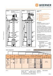
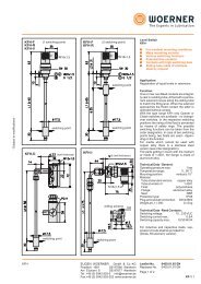
Pneumatisch gelüftete Federdruck-Lamellenbremsen für Trockenlauf Baureihe 0422 -. . 0 9 Zentrierlänge Bauform für Anordnung der Bremse ohne zentrierende Funktion zwischen An- <strong>und</strong> Abtriebsseite. Flansch Ansicht Y Notschaltung: Bei Ausfall der Pneumatik Kolben mittels Schrauben lüften! Träger Anschlagscheibe
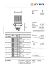
Pneumatisch gelüftete Federdruck-Lamellenbremsen für Trockenlauf Baureihe Größe Ms Nm Mü Nm Lüftdruck min bar Betriebsdruck max bar Drehzahl max bei Schaltung 1) min -1 Drehzahl max bei Leerlauf min -1 Hubvolumen cm 3 J innen kgcm 2 Gewicht kg ØA vorgebohrt A max H 7 Nut DIN 6885 A H 7 Nut DIN 6885 Vorzugsbohrungen 2) A H 7 Nut DIN 6885 Durchmesser Längenmaße A H7 Nut DIN 6885 B d9 C D H8 D1 g7 E E1 F f7 F1 G G1 H H7 K J1 J2 L L1 H7 N M 3) O O1 P P1 R R1 S T U V max W X X1 Y Z Y 1 Z 1 0422-...-Größe-002000 0422-..1-Größe-000000 07 11 15 23 25 31 39 47 55 63 69 25 31 39 47 55 20 28 50 120 125 200 320 550 900 1500 2450 125 200 320 550 900 23 30 58 130 140 230 370 635 1040 1730 2700 140 230 370 635 1040 5 5 10 10 14854 11330 9758 9482 7427 6521 5547 4341 3537 2925 2494 7427 6521 5547 4341 3537 16977 12948 11152 10836 8488 7453 6340 4961 4042 3343 2851 8488 7453 6340 4961 4042 5,2 4 6,3 15,7 17 28 41 61 91 137 204 17 28 41 61 91 0,6 1,5 3,25 7 14,25 25 65 175 550 1150 2600 14,25 25 65 175 550 2,2 3,5 6,5 7,8 11 16 21,5 30 45,5 66,5 130 11 14 18,5 27 51 – - - - 20 - - - 60 70 80 20 20 30 40 60 18 30 30 40 45 55 65 90 110 140 150 45 55 65 90 110 6x 8x 8x 12x 14x 16x 18x 25x 28x 36x 36x 14x 16x 18x 25x 8x 2,8 3,3 3,3 2,2 3,8 4,3 4,4 5,4 6,4 8,4 8,4 3,8 4,3 4,4 5,4 6,4 25 25 35 40 50 60 8x 8 10x 12x 14x 18x 3,3 3,3 3,3 3,3 3,8 4,4 30 35 45 50 8x 10x 14x 14x 3,3 3,3 3,8 3,8 30/25 30 8x 8x 3,3 3,3 33 49,6 51,6 60 70 81,4 100 127 148 184 216 70 81,4 100 127 148 35 52 54 62 72 85 102 132 155 188 220 72 85 102 132 155 55 69 80 82,2 112 126 144 182 228 279 328 – – – – – – – – – – – – – – – – 130 145 170 205 250 73 90 100 115 135 160 185 220 265 315 370 – – – – – – – – – – – – – – – – 155 170 195 230 290 83 105 120 135 155 180 205 245 290 345 400 – – – – – – – – – – – – – – – – 170 190 215 250 315 M6 M6 M8 M8 M8 M10 M10 M12 M14 M16 M16 – – – – – – – – – – – – – – – – 136 151 172 210 265 27 45 45 52 65 80 95 120 140 180 205 – – – – – – – – – – – – – – – – 65 80 95 120 140 – – – – – – – – – – – M8 M10 M10 M10 M12 – – – – – – – – – – – 8,5 10,5 10,5 10,5 13 – 57 60 66 88 103 118 152 180 220 280 88 103 118 152 180 – – – – – – – – – – – 130 145 170 205 250 – M6 M6 M6 M8 M8 M8 M10 M12 M12 M12 M8 M8 M8 M10 M12 M10 M12 M16 x1 x1,5 x1,5 G1/8 G1/4 G3/8 59 67 77 81 90 95 100 110 135 145 165 – – – – – – – – – – – – – – – – 100 104 112 122 150 11 13 13 14 20 15 20 20 25 25 25 – – – – – – – – – – – – – – – – 49 52 53 58 63 54 61 69 73 82 86 91 99 122 130 148 – – – – – – – – – – – – – – – – 11 12 13 13 15 7 8 10 10 10 11 11 14 16 18 20 10 11 11 14 16 21 22 24 25 32 33 38 40 58 59 70 32 33 38 40 58 35 38 44 45 52 55 60 68 90 95 110 52 55 60 68 90 – – – – – – – – – – – 5 5 6 6 6 – – – – – – – – – – – 38 40 42 46 50 2 2 2 2 2 2 2 3 3 3 3 – – – – – – – – – – – – – – – – 4 3 4 4 6 7 8 9 10 11 12 12 14 16 18 20 – – – – – 21 24 27 30 32 34 34 38 41 46 53 – – – – – 8 9 13 13 13 13 13 13 13 13 14 13 13 13 13 13 _ 15 15 15 20 20 20 20 20 20 25 20 20 20 20 20 1) Wärmeberechnung erforderlich. 2) Fettgedruckte Bohrungen sind lagerhaltig. 3) Rohrgewinde G.... nach ISO 228/1 bzw. BS 2779. Reibpaarung Passungen Stahl/organischer Reibbelag (Größe 07: Stahl/Sinterbelag). Nur für Trockenlauf! Das Lamellenpaket ist gegen das Eindringen von Schmiermitteln abzudichten! für Bohrung <strong>und</strong> Nut siehe Register 1 "Technische Gr<strong>und</strong>lagen" Baureihe 0422 Blatt-Nr. DE 6.47.00 Ausgabe 08.2004