SPIDEX® – die elastische Kupplung SPIDEX® – the elastic coupling
SPIDEX® – die elastische Kupplung SPIDEX® – the elastic coupling
SPIDEX® – die elastische Kupplung SPIDEX® – the elastic coupling

Sie wollen auch ein ePaper? Erhöhen Sie die Reichweite Ihrer Titel.
YUMPU macht aus Druck-PDFs automatisch weboptimierte ePaper, die Google liebt.
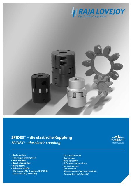
<strong>SPIDEX®</strong> <strong>–</strong> <strong>die</strong> <strong>elastische</strong> <strong>Kupplung</strong><br />
<strong>SPIDEX®</strong> <strong>–</strong> <strong>the</strong> <strong>elastic</strong> <strong>coupling</strong><br />
• Drehelastisch<br />
• Schwingungsdämpfend<br />
• Axial steckbar<br />
• Durchschlagsicher<br />
• Wartungsfrei<br />
• Nabenwerkstoffe:<br />
Aluminium (Al), Grauguss (GG/GGG),<br />
Sinterstahl (Si), Stahl (St)<br />
• Torsional <strong>elastic</strong>ity<br />
• Dampening<br />
• Blind assembly<br />
• Safe against break-down<br />
• No maintenance<br />
• Hub material:<br />
Aluminium (Al), Cast Iron (GG/GGG),<br />
Sintered Steel (Si), Steel (St)
www.rajalovejoy.com<br />
2<br />
Funktionsweise Technical descripton<br />
Abb. 1<br />
Unbelasteter Polyurethan-Zahn<br />
Fig. 1<br />
Unloaded Polyurethane-tooth<br />
Abb. 2<br />
Belasteter Polyurethan-Zahn<br />
Fig. 2<br />
Loaded Polyurethane-tooth<br />
Elastische <strong>Kupplung</strong>en sind in der Lage, kurzzeitige Drehmomentstöße<br />
durch zeitweilige <strong>elastische</strong> Speicherung eines Teiles der Stoßenergie zu mildern.<br />
Der Ungleichförmigkeitsgrad der Bewegungs- und Kraftübertragung<br />
wird somit kleiner. Elastische <strong>Kupplung</strong>en dämpfen den Körperschall und<br />
tragen somit zur Geräuschminderung bei. Die <strong>elastische</strong> <strong>SPIDEX®</strong>-<strong>Kupplung</strong><br />
überträgt das Drehmoment formschlüssig und durchschlagsicher. Der ballig<br />
profilierte Evolventenzahn (Abb.1) gestattet den Ausgleich von Radial- und<br />
Winkelverlagerungen der zu verbindenden Wellen. Er besteht aus einem<br />
<strong>the</strong>rmoplastischen Polyurethan-Elastomer, ist ausschließlich auf Druck belastbar<br />
und zeichnet sich darüber hinaus durch hohe Verschleißfestigkeit<br />
und Elastizität, gute Dämpfungseigenschaften und gute Beständigkeit gegen<br />
Öle, Fette, viele Lösemittel, Witterungseinflüsse und Ozon aus. Hinzu<br />
kommt eine gute Hydrolyse- und Tropenbeständigkeit.<br />
Die Einsatztemperaturen liegen zwischen -40 °C und +100 °C. Kurzzeitige<br />
Temperaturspitzen bis +120 °C sind zulässig.<br />
Die Standardhärte des Zahnkranzes beträgt 92° Shore A. Für niedrige Drehmomente<br />
kann auch ein Zahnkranz mit 80° Shore A und für höhere Drehmomente<br />
mit 95° bis 98° Shore A eingesetzt werden. Durch <strong>die</strong> aus Abb.<br />
1 und Abb. 2 zu ersehende Balligkeit nehmen <strong>die</strong> Zähne des Zahnkranzes<br />
mit zunehmender Verformung eine überproportional wachsende Verformungsenergie<br />
auf.<br />
Der Wert der Federsteife CT des Zahnkranzes nimmt mit Vergrößerung des<br />
relativen Drehwinkels f zu. Folglich arbeitet <strong>die</strong> <strong>Kupplung</strong> bei geringer Kraftübertragung<br />
relativ weich und mit zunehmendem Drehmoment immer<br />
härter. Hieraus ergibt sich eine progressive Federkennlinie gemäß Abb. 3.<br />
Die dynamische Federkennlinie hat einen geringfügig steileren Verlauf.<br />
Die in Abb. 3 dargestellte Dämpfungsarbeit bewirkt <strong>die</strong> in Abb. 4 ersichtliche<br />
Dämpfung von Drehmomentstößen.<br />
Ein besonderer Vorteil der progressiven Federkennlinie liegt im Resonanzverhalten<br />
der <strong>SPIDEX®</strong>-<strong>Kupplung</strong>. Da <strong>die</strong> kritische Resonanzdrehzahl abhängig<br />
von der Federsteife CT ist, letztere sich jedoch mit Verschiebung des<br />
Arbeitspunktes ändert, ergibt sich eine Verstimmung des Systems gemäß<br />
Abb. 5, welche <strong>die</strong> Gefahr des Aufschaukelns verringert.<br />
Die progressive Kennlinie schützt somit vor allem <strong>die</strong> <strong>Kupplung</strong> gegen<br />
unzulässige Überbeanspruchung. Darüber hinaus kann <strong>die</strong> Federsteife CT<br />
durch eine entsprechende Wahl der Shorehärte beeinflusst werden. Eine<br />
größere Shorehärte verlagert <strong>die</strong> Resonanzdrehzahl in einen höheren, eine<br />
niedrigere Shorehärte in einen niedrigeren Bereich. Im Zweifelsfalle empfehlen<br />
wir eine Berechnung des Systems mittels der antriebs- und lastseitigen<br />
Massenträgheitsmomente.<br />
<strong>Kupplung</strong> bestehend aus:<br />
Zwei <strong>Kupplung</strong>snaben mit<br />
<strong>elastische</strong>m Zahnkranz<br />
Coupling assembled:<br />
Two hubs with <strong>elastic</strong> spider<br />
Elastic <strong>coupling</strong>s reduce intermittent short period torsional shocks, by briefly<br />
storing <strong>elastic</strong>ally part of this shock energy. Any degree of uneven movement<br />
and load transference is consequently reduced. Elastic <strong>coupling</strong>s restrain body<br />
resonance, and <strong>the</strong>refore contribute to noise reduction. The <strong>elastic</strong> <strong>SPIDEX®</strong><strong>coupling</strong><br />
transmits <strong>the</strong> torque safe against break-down. The convex generated<br />
profiled tooth crown, see fig. 1, allows compensation of radial and angular<br />
displacements of <strong>the</strong> two connected shafts. It consists of a <strong>the</strong>rmoplastic Polyurethane<br />
elastomer, which is exclusively pressure loaded and designed for high<br />
abrasion resistance and <strong>elastic</strong>ity, and to have good damping characteristics,<br />
and to be resistant to oils, greases, many solvents, atmospheric effects and<br />
ozone, as well as good resistance to hydrolysis in tropical conditions.<br />
The operating temperatures are between -40 °C and +100 °C. Short temperature<br />
peaks up to +120°C are admissible.<br />
The standard hardness of <strong>the</strong> spider is 92° Shore A. For low torques a spider of<br />
80° Shore A, can be used and for higher torques a spider of 95° to 98° Shore A,<br />
can be used. From figures 1 and 2, it can be seen that <strong>the</strong> convex rim of <strong>the</strong> tooth<br />
takes higher proportion of deformation-energy, <strong>the</strong> more deformation increases.<br />
The value of <strong>the</strong> torsional stiffness CT of <strong>the</strong> tooth crown increases with <strong>the</strong><br />
torsional angle f. Consequently, <strong>the</strong> <strong>coupling</strong> is relatively soft under small load<br />
conditions and becomes harder and harder as <strong>the</strong> torque increases. This causes<br />
a progressive torsion curve, as shown in fig. 3. The dynamic torsion curve has an<br />
insignificantly steeper course.<br />
The damping energy shown in fig. 3 results in <strong>the</strong> damping of torque shocks as<br />
shown in fig. 4.<br />
Special advantage of <strong>the</strong> progressive torsion characteristic is in <strong>the</strong> resonance<br />
suppression achieved by <strong>the</strong> <strong>SPIDEX®</strong>-<strong>coupling</strong>, as <strong>the</strong> critical resonance speed<br />
depends on <strong>the</strong> torsional stiffness CT (see fig. 5).<br />
The progressive curve <strong>the</strong>refore mainly protects <strong>the</strong> <strong>coupling</strong> against inadmissible<br />
overstressing. Fur<strong>the</strong>rmore, <strong>the</strong> torsional stiffness CT of <strong>the</strong> spider can be<br />
influenced by <strong>the</strong> choice of an appropriate Shore hardness material. A larger<br />
Shore hardness moves <strong>the</strong> resonance speed higher, and a lower Shore hardness<br />
moves resonance speed into a lower range. If in doubt, we recommend a calculation<br />
of <strong>the</strong> system parameters by using <strong>the</strong> moments of inertia of <strong>the</strong> driving<br />
and driven sides.<br />
2<br />
3<br />
Progressive<br />
Kennlinie<br />
Progressive<br />
characteristi c<br />
5<br />
1<br />
4<br />
Abb. 3<br />
Progressive Drehfederkennlinie mit<br />
Dämpfung erzeugender Hysterese<br />
Fig. 3<br />
Progressive torsional characteristic with<br />
damping, effected by hysterisis<br />
Abb. 4<br />
Drehmomentstoß mit und ohne Dämpfung<br />
Fig. 4<br />
Torque shock with and without damping<br />
Abb. 5<br />
Resonanzverhalten <strong>elastische</strong>r <strong>Kupplung</strong>en mit linear und<br />
progressiv ansteigender Drehfederkennlinie<br />
Fig. 5<br />
Resonance suppression of <strong>elastic</strong> <strong>coupling</strong>s with linear and<br />
progressively increasing torsional characteristic
3<br />
Typenbezeichnung <strong>Kupplung</strong>snabe Model type of hub<br />
KL ST<br />
A 38/45 . A35 x 31 L = 70 SO<br />
Standard<br />
Standard<br />
Klemmnabe<br />
Clamping hub<br />
<strong>–</strong><br />
KL<br />
Verlängerte Naben<br />
Extended hub length<br />
<strong>–</strong><br />
70<br />
Standard<br />
Standard<br />
Siehe Seite 6<br />
See page 6<br />
Nabenwerkstoff<br />
Material of hub<br />
Nabengröße/Nabenausführung<br />
Size/Design of hub<br />
Beispiel Wellenbohrung<br />
Example finish bores<br />
Sonderbearbeitung<br />
Special machining<br />
Aluminium / Aluminium<br />
Sinterstahl / Sintered steel<br />
Grauguss / Cast iron<br />
Sphäroguss / SG<br />
Stahl / Steel<br />
ALU<br />
SI<br />
GG<br />
GGG<br />
ST<br />
Nabenausführung A / Hub A<br />
A15<br />
Nabenausführung B / Hub B<br />
A14/16<br />
A19 A19/24<br />
A24<br />
CJ24/32<br />
A28 A28/38<br />
A38 A38/45<br />
A42 A42/55<br />
A48 A48/60<br />
A55 A55/70<br />
A65 A65/75<br />
A75 A75/90<br />
A90 A90/100<br />
Ung. Ungebohrt / Unbored<br />
Vorg. Vorgebohrt / Prebored<br />
38H7 ISO-Standard H7 **<br />
B17 Konisch / Tapered *<br />
F Zöllig / Inch bored ***<br />
*** SAE 16/32Z13 SAE<br />
*** A35x31 DIN 5482<br />
*** N30x2x14x9G DIN 5480<br />
* Siehe Seite 10 / See page 10<br />
** Siehe Seite 11 / See page 11<br />
*** Siehe Seite 12 / See page 12<br />
Profile<br />
Splines<br />
<strong>–</strong><br />
SO<br />
Standard<br />
Standard<br />
Sonderzeichnung<br />
Special drawing<br />
A100 A100/110<br />
A110 A110/125<br />
A125 A125/145<br />
Typenbezeichnung <strong>Kupplung</strong>sflansch<br />
Model type of flange<br />
GGG<br />
A 38 . FLANSCH<br />
F<br />
Flanschwerkstoff<br />
Material of flange<br />
Sphäroguss SG<br />
GGG40<br />
GGG<br />
Flanschtyp<br />
Type of flange<br />
A28<br />
A38<br />
A42<br />
A48<br />
A55<br />
A65<br />
A75<br />
A90<br />
A100<br />
Flanschausführung<br />
Design of flange<br />
<strong>–</strong><br />
F<br />
BF<br />
CFA<br />
CFB<br />
CFD<br />
Ungebohrt<br />
Unbored<br />
Durchgangslöcher<br />
Through holes<br />
Gewindebohrungen<br />
Threaded holes<br />
Ausführung für<br />
Hydraulikpumpen<br />
Fabrikat LINDE<br />
Designed for<br />
hydraulic pumps<br />
manufacturer LINDE
www.rajalovejoy.com<br />
4<br />
Der Auswahlprozess zur Größenbestimmung<br />
Selection process for sizing determination<br />
Schritt 1: Bestimmung des Nenndrehmoments Ihrer Anwendung:<br />
Step 1: Determine <strong>the</strong> nominal torque of your application:<br />
T KN [Nm] =<br />
P[kW] x 9550<br />
U/min [1/min]<br />
T KN [Nm] =<br />
P[kW] x 9550<br />
U/min [1/min]<br />
Schritt 2: Berechnung des Betriebsfaktors Ihrer Anwendung mit der Tabelle<br />
auf Seite 5. Der Gesamtbetriebsfaktor (K) ergibt sich aus:<br />
K = K1* x K2* x K3*<br />
Schritt 3: Berechnung des konstruktiven Drehmoments (∆T Kmax ) Ihrer<br />
Anwendung.<br />
Konstruktives Drehmoment (∆T Kmax ) =<br />
Nenndrehmoment (T KN ) x Betriebsfaktor (K).<br />
Schritt 4: Unter Verwendung der Elastomer- Leistungsdatentabellen auf<br />
der Seite 7 den Urethan-Shore-Härtegrad auswählen, der am Besten<br />
den relativen Dämpfungsanforderungen Ihrer Anwendung<br />
entspricht.<br />
Schritt 5: Finden Sie als nächstes <strong>die</strong> Spalten, in denen <strong>die</strong> Werte<br />
T KN und T Kmax in Nm gelistet sind und vergleichen Sie <strong>die</strong>se mit dem<br />
Wert ∆T Kmax für Ihre Anwendung. Stellen Sie sicher, dass <strong>die</strong> Werte<br />
des Mitnehmers (Sterns) größer als <strong>die</strong> Anwendungswerte sind.<br />
Schritt 6: Nachdem <strong>die</strong> Größe unter Verwendung der Drehmomentwerte<br />
ausgewählt ist, stellen Sie mit Hilfe der Tabelle auf Seite 8 sicher,<br />
dass der erforderliche Bohrungsdurchmesser in <strong>die</strong> <strong>Kupplung</strong><br />
passt.<br />
Step 2: Calculate your Application Service Factor using <strong>the</strong> charts on page 5.<br />
The total Service Factor (K) will be:<br />
K = K1* x K2* x K3*<br />
Step 3: Calculate <strong>the</strong> design torque (∆T Kmax ) of your application.<br />
Design torque (∆T Kmax ) =<br />
Nominal torque (T KN ) x service factor (K).<br />
Step 4: Using <strong>the</strong> Elastomer performance data charts on page 7 select <strong>the</strong> urethane<br />
shore hardness which best corresponds to your relative damping<br />
needs in <strong>the</strong> application.<br />
Step 5: Next find <strong>the</strong> columns listing T KN and T Kmax values listed in Nm and compare<br />
<strong>the</strong>m against <strong>the</strong> ∆T Kmax figure for your application. Make sure that<br />
<strong>the</strong> spider/<strong>coupling</strong> size values are larger than <strong>the</strong> application values.<br />
Step 6: Once <strong>the</strong> size is selected using <strong>the</strong> torque values, check <strong>the</strong> table on<br />
page 8 to make sure <strong>the</strong> bore size needed will fit in <strong>the</strong> <strong>coupling</strong>.<br />
Step 7: Double check <strong>the</strong> overall dimensions of <strong>the</strong> <strong>coupling</strong> to ensure that it<br />
will fit in <strong>the</strong> space allowed for <strong>the</strong> <strong>coupling</strong> in <strong>the</strong> application.<br />
Schritt 7: Überprüfen Sie sorgfältig das Gesamtmaß der <strong>Kupplung</strong>, um zu<br />
gewährleisten, dass <strong>die</strong> <strong>Kupplung</strong> in den Einbauraum passt.<br />
Definition der Begriffe<br />
Definition of terms<br />
T KN<br />
Nenndrehmoment der <strong>Kupplung</strong><br />
T KN<br />
Rated <strong>coupling</strong> torque<br />
T Kmax<br />
Maximales Drehmoment der <strong>Kupplung</strong><br />
T Kmax<br />
Maximum torque of <strong>the</strong> <strong>coupling</strong><br />
P [kW]<br />
Leistung in Kilowatt<br />
P [kW]<br />
Power in kilowatts<br />
U/min [1/min]<br />
Umdrehungen pro Minute<br />
U/min [1/min]<br />
Revolutions per minute<br />
Nm<br />
Newtonmeter<br />
Nm<br />
Newton meters<br />
ΔT Kmax<br />
Maximales Drehmoment der Anwendung<br />
ΔT Kmax<br />
Maximum torque of <strong>the</strong> application<br />
T KW<br />
Variierende Belastung einer Anwendung<br />
T KW<br />
Varying load of an application in kilowatts<br />
in Kilowatt (DIN 740 Teil 2)<br />
(DIN 740 part 2)<br />
K<br />
Betriebsfaktor<br />
K<br />
Application Service Factor<br />
* siehe nächste Seite *see next page
5<br />
Anwendungs-Betriebsfaktoren<br />
Application service factors<br />
K1<br />
K1<br />
Betriebsfaktor K1<br />
Application service factor K1<br />
Gleichmäßiger Betrieb mit kleinen Beschleunigungsmassen.<br />
Hydraulik- und Zentrifugalpumpen, kleine Generatoren,<br />
Gebläse, Lüfter, Venlilatoren, Band/Schraubenförderer.<br />
1.0<br />
Uniform operation with small masses to be accelerated.<br />
Hydraulic and centrifugal pumps, light generators,<br />
blowers, fans, ventilators, belt/screw conveyors.<br />
1.0<br />
Gleichmäßiger Betrieb mit mittleren Beschleunigungsmassen.<br />
Blechbiegemaschinen, Holzbearbeitungsmaschinen, Walzwerke,<br />
Textilmaschinen, Mischer.<br />
1.2<br />
Uniform operation with medium masses to be<br />
accelerated. Sheet metal bending machines, wood<br />
workingg machines, mills, textile machines, mixersg<br />
1.2<br />
Ungleichmäßiger Betrieb mit mittleren Beschleunigungsmassen.<br />
Rotierende Öfen, Druckpressen, Generaloren, Schredder, Wickelmaschinen,<br />
Soinnmaschinen, Pumpen für dickflüssige Fluide.<br />
1.3<br />
Irregular operation with medium masses to be<br />
accelerated. Rotating ovens, printing presses,<br />
generators, shredders, winders, spinning machines,<br />
pumps for viscous fluids<br />
1.3<br />
Ungleichmäßiger Betrieb und Stoßbelastungen mit mittleren<br />
Beschleunigungsmassen. Betonmischer, Fallhämmer, Seilbahnen,<br />
Papiermühlen, Kompressionspumpen, Propellerpumpen,<br />
Seilwinden, Zentrifugen.<br />
1.4<br />
Irregular operation and shocks, with medium masses to<br />
be accelerated Goncrete mixers, drop hammers,<br />
cable cars, paper mills, compression pumps, propeller<br />
pumps, rope winders, centrifuges<br />
1.4<br />
Ungleichmäßiger Betrieb und starke Stoßbelastungen mit<br />
großen Beschleunigungsmassen. Bagger, Hammermühlen,<br />
Kolbenpumpen, Pressen, Erdbohrmaschinen, Scheren,<br />
Schmiedepressen, Steinbrecher.<br />
1.6<br />
Irregular operation and heavy shocks, with large<br />
masses to be accelerated. Excavators, hammer mills,<br />
piston pumps, presses, rotary boring machines, shears,<br />
forge presses, stone crushers<br />
1.6<br />
Ungleichmäßiger Betrieb und sehr starke Stoßbelastungen mit<br />
sehr großen Beschleunigungsmassen.<br />
Kolbenkompressoren und Pumpen ohne Drehzahlregelung,<br />
schwere Walzensätze, Schweißmaschinen, Ziegelpressen,<br />
Steinbrecher.<br />
1.8<br />
Irregular operation and very heavy shocks, with very<br />
large masses to be acceleratedg Piston type compressors<br />
and pumps without speed variations, heavy roll<br />
sets, welding machines, brick Dresses, stone crushers.<br />
1.8<br />
K2 <strong>–</strong> für Anläufe pro Stunde<br />
K2 <strong>–</strong> for starts per hour<br />
Anläufe pro Stunde 100 200 400 800 Starts per hour 100 200 400 800<br />
Betriebsfaktor K2 1.0 1.2 1.4 1.6 Service factor K2 1.0 1.2 1.4 1.6<br />
K3 <strong>–</strong> für Umgebungstemperaturen<br />
K3 <strong>–</strong> for ambient temperature<br />
Umgebungstemperatur<br />
-30 bis +30 °C +40 °C +60 °C +80 °C<br />
Ambient<br />
temperature<br />
-30 to +30 °C +40 °C +60 °C +80 °C<br />
Betriebsfaktor K3 1.0 1.2 1.4 1.8 Service factor K3 1.0 1.2 1.4 1.8
www.rajalovejoy.com<br />
6<br />
SPIDEX ® -<strong>Kupplung</strong>en für IEC-Normmotoren, Zahnkranz 92° Shore A<br />
SPIDEX ® -Couplings for IEC-standard motors, spider 92° Shore A<br />
Motorbaugröße<br />
Motor<br />
size<br />
Welle<br />
Shaft<br />
D x I [mm]<br />
= 1500<br />
[1/min]<br />
= 3000<br />
[1/min]<br />
n = 750 [1/min]<br />
Leistung P<br />
Power P<br />
kW<br />
T AN<br />
[Nm]<br />
Größe<br />
Size<br />
T K<br />
max<br />
[Nm]<br />
n = 1000 [1/min]<br />
Leistung P<br />
Power P<br />
Die <strong>Kupplung</strong>svorauswahl erfolgte für den Normalbetrieb ohne Berücksichtigung von Betriebsfaktoren.<br />
Coupling selection made for normal operation. For o<strong>the</strong>r conditions please notify <strong>the</strong> safety factors.<br />
kW<br />
T AN<br />
[Nm]<br />
Größe<br />
Size<br />
T K<br />
max<br />
[Nm]<br />
n = 1500 [1/min]<br />
Leistung P<br />
Power P<br />
kW<br />
T AN<br />
[Nm]<br />
Größe<br />
Size<br />
T K<br />
max<br />
[Nm]<br />
n = 3000 [l/min]<br />
Leistung P<br />
Power P<br />
56 9 x 20 <strong>–</strong> <strong>–</strong> 14/16 15 <strong>–</strong> <strong>–</strong> 14/16 15 0.06 0.4 14/16 15 0.09 0.3 14/16 15<br />
15 15 0.09 0.6 15 0.12 0.4 15<br />
63 11 x 23 <strong>–</strong> <strong>–</strong> <strong>–</strong> <strong>–</strong> 0.12 0.9 0.18 0.6<br />
<strong>–</strong> 0.18 1.2 0.25 0.9<br />
71 14 x 30 <strong>–</strong> <strong>–</strong> <strong>–</strong> <strong>–</strong> 0.25 1.8 0.37 1.3<br />
0.37 2.5 0.55 1.9<br />
80 19 x 40 <strong>–</strong> <strong>–</strong> 19/24 20 0.37 3.7 19/24 20 0.55 3.7 19/24 20 0.75 2.5 19/24 20<br />
0.55 5.5 0.75 5.0 1.1 3.7<br />
90 S 24 x 50 <strong>–</strong> <strong>–</strong> 0.75 7.9 1.1 7.5 1.5 4.9<br />
90 L <strong>–</strong> <strong>–</strong> 1.1 11 1.5 10 2.2 7.4<br />
100 L 28 x 60 0.75 11 24/32 70 1.5 15 24/32 70 2.2 15 24/32 70 3 9.8 24/32 70<br />
1.1 16 3 20<br />
112 M 1.5 21 2.2 22 4 27 4 13<br />
132 S 38 x 80 2.2 29 28/38 190 3 30 28/38 190 5.5 36 28/38 190 5.5 18 28/38 190<br />
7.5 25<br />
132 M 3 40 4 39 7.5 49<br />
5.5 55<br />
160 M 42 x 110 4 54 38/45 380 7.5 74 38/45 380 11 72 38/45 380 11 35 38/45 380<br />
5.5 74 15 49<br />
160 L 7.5 100 11 108 15 98 18.5 60<br />
180 M 48 x 110 42/55 530 42/55 530 18.5 121 42/55 530 22 72 42/55 530<br />
180 L 11 147 15 147 22 144<br />
200 L 55 x 110 15 196 18.5 185 30 195 30 97<br />
22 215 37 117<br />
225 S 60 x 140 55 x 110 18.5 245 48/60 620 48/60 620 37 245 48/60 620<br />
225 M 22 294 30 292 45 294 45 146<br />
250 M 65 x 140 60 x 140 30 390 65/75 1250 37 361 55/70 820 55 357 55/70 820 55 176 48/60 620<br />
280 S 75 x 140 65 x 140 37 490 45 440 65/75 1250 75 487 65/75 1250 75 245 55/70 820<br />
280 M 45 585 55 536 90 584 90 294<br />
315 S 80 x 170 55 715 75/90 2560 75 730 75/90 2560 110 714 75/90 2560 110 350<br />
315 M 75 970 90/100 4800 90 876 132 857 132 420 65/75 1250<br />
315 L 90 1170 110 1070 90/100 4800 160 1030 90/100 4800 160 513<br />
110 1420 132 1280 200 1290 200 641<br />
355 L 95 x 170 75 x 140 132 1710 160 1550 250 1610 250 801 75/90 2560<br />
160 2070 100/110 6600 200 1930 315 2020 315 1010<br />
200 2580 250 2420<br />
100/110 6600 90/100 4800<br />
400 L 100 x 210 80 x 170 250 3230 110/125 9600 315 3040 2280 100/110 6600 355 1140<br />
2560 400 1280<br />
kW<br />
T AN<br />
[Nm]<br />
Größe<br />
Size<br />
T K<br />
max<br />
[Nm]
7<br />
Technische Daten<br />
Technical data<br />
Zahnkranz<br />
Spider<br />
80° Shore<br />
Skala A<br />
Farbe:<br />
Blau<br />
Scale A<br />
Color:<br />
Blue<br />
92° Shore<br />
Skala A<br />
Farbe:<br />
Weiß<br />
Scale A<br />
Color:<br />
White<br />
98° Shore<br />
Skala A<br />
Farbe: Rot<br />
Scale A<br />
Color: Red<br />
95° Shore<br />
Skala A<br />
Farbe: Rot<br />
Scale A<br />
Color: Red<br />
64° Shore<br />
Skala D<br />
Farbe:<br />
Grün<br />
Scale D<br />
Color:<br />
Green<br />
Größe<br />
Size<br />
Drehmoment<br />
Torque<br />
[Nm]<br />
Nenn<br />
Contin.<br />
T KN<br />
Maximal<br />
Maximum<br />
T Kmax<br />
Max. Drehzahl<br />
Max. rotation<br />
n [1/min]<br />
Wechsel V=<br />
T KW 30 m/s 40 m/s<br />
Alternat.<br />
Verdrehwinkel<br />
Torsional angle<br />
T KN<br />
φ KN<br />
Drehfedersteife<br />
Torsional stiffness<br />
C dyn [Nm/rad]<br />
T Kmax<br />
φ Kmax 1.00 T KN 0.75 T KN 0.5 T KN 0.25 T KN<br />
14/16, 15 4 8 1 19000 <strong>–</strong> 6.4° 10° <strong>–</strong> <strong>–</strong> <strong>–</strong> <strong>–</strong> 0.85<br />
19/24 4.9 9.7 1.3 14000 19000 3.2° 5° 0.25 x 10³ 0.21 x 10³ 0.17 x 10³ 0.11 x 10³<br />
24/32 17 34 4.4 10600 14000 0.90 x 10³ 0.75 x 10³ 0.60 x 10³ 0.40 x 10³<br />
28/38 46 92 12 8500 11800 2.30 x 10³ 1.93 x 10³ 1.52 x 10³ 1.03 x 10³<br />
38/45 93 185 24 7100 9500 4.10 x 10³ 3.45 x 10³ 2.75 x 10³ 1.85 x 10³<br />
42/55 130 260 34 6000 8000 5.90 x 10³ 5.05 x 10³ 4.00 x 10³ 2.70 x 10³<br />
48/60 150 300 39 5600 7100 8.00 x 10³ 6.81 x 10³ 5.30 x 10³ 3.60 x 10³<br />
55/70 180 360 47 4750 6300 9.95 x 10³ 8.45 x 10³ 6.71 x 10³ 4.50 x 10³<br />
65/75 205 410 53 4250 5600 13.05 x 10³ 11.08 x 10³ 8.79 x 10³ 5.89 x 10³<br />
75/90 475 950 124 3550 4750 22.00 x 10³ 18.44 x 10³ 14.65 x 10³ 9.85 x 10³<br />
90/100 1175 2350 306 2800 3750 45.00 x 10³ 38.20 x 10³ 30.05 x 10³ 20.00 x 10³<br />
100/110 1610 3220 419 2500 3350 75.69 x 10³ 64.00 x 10³ 50.20 x 10³ 34.00 x 10³<br />
110/125 1950 3900 507 2240 3000 100.00 x 10³ 84.00 x 10³ 67.00 x 10³ 45.00 x 10³<br />
125/145 2440 4880 634 2000 2650 140.00 x 10³ 118.00 x 10³ 94.00 x 10³ 63.06 x 10³<br />
14/16, 15 7.5 15 2.0 19000 <strong>–</strong> 6.4° 10° 0.38 x 10³ 0.31 x 10³ 0.24 x 10³ 0.14 x 10³ 0.75<br />
19/24 10 20 2.6 14000 19000 3.2° 5° 1.28 x 10³ 1.05 x 10³ 0.80 x 10³ 0.47 x 10³<br />
24/32 35 70 9.1 10600 14000 4.86 x 10³ 3.98 x 10³ 3.01 x 10³ 1.79 x 10³<br />
28/38 95 190 25 8500 11800 10.90 x 10³ 8.94 x 10³ 6.76 x 10³ 4.01 x 10³<br />
38/45 190 380 49 7100 9500 21.05 x 10³ 17.26 x 10³ 13.05 x 10³ 7.74 x 10³<br />
42/55 265 530 69 6000 8000 23.74 x 10³ 19.47 x 10³ 14.72 x 10³ 8.73 x 10³<br />
48/60 310 620 81 5600 7100 36.70 x 10³ 30.09 x 10³ 22.75 x 10³ 13.49 x 10³<br />
55/70 410 820 107 4750 6300 50.72 x 10³ 41.59 x 10³ 31.45 x 10³ 18.64 x 10³<br />
65/75 625 1250 163 4250 5600 97.13 x 10³ 79.65 x 10³ 60.22 x 10³ 35.70 x 10³<br />
75/90 1280 2560 333 3550 4750 113.32 x 10³ 92.92 x 10³ 70.26 x 10³ 41.65 x 10³<br />
90/100 2400 4800 624 2800 3750 190.09 x 10³ 155.87 x 10³ 117.86 x 10³ 69.86 x 10³<br />
100/110 3300 6600 858 2500 3350 253.08 x 10³ 207.53 x 10³ 156.91 x 10³ 93.01 x 10³<br />
110/125 4800 9600 1248 2240 3000 311.61 x 10³ 255.52 x 10³ 193.20 x 10³ 114.52 x 10³<br />
125/145 6650 13300 1729 2000 2650 474.86 x 10³ 389.39 x 10³ 294.41 x 10³ 174.51 x 10³<br />
14/16, 15 12.5 25 3.3 19000 <strong>–</strong> 0.56 x 10³ 0.46 x 10³ 0.35 x 10³ 0.21 x 10³ 0.7<br />
19/24 17 34 4.4 14000 19000 6.4° 10° 2.92 x 10³ 2.39 x 10³ 1.81 x 10³ 1.07 x 10³<br />
24/32 60 120 16 10600 14000 3.2° 5° 9.93 x 10³ 8.14 x 10³ 6.16 x 10³ 3.65 x 10³<br />
28/38 160 320 42 8500 11800 26.77 x 10³ 21.95 x 10³ 16.60 x 10³ 9.84 x 10³<br />
38/45 325 650 85 7100 9500 48.57 x 10³ 39.83 x 10³ 30.11 x 10³ 17.85 x 10³<br />
42/55 450 900 117 6000 8000 54.50 x 10³ 44.69 x 10³ 33.79 x 10³ 20.03 x 10³<br />
48/60 525 1050 137 5600 7100 65.29 x 10³ 53.54 x 10³ 40.48 x 10³ 24.00 x 10³<br />
55/70 685 1370 178 4750 6300 94.97 x 10³ 77.88 x 10³ 58.88 x 10³ 34.90 x 10³<br />
65/75 940 1880 244 4250 5600 3.2° 5° 129.51 x 10³ 106.20 x 10³ 80.30 x 10³ 47.60 x 10³<br />
75/90 1920 3840 499 3550 4750 197.50 x 10³ 161.95 x 10³ 122.45 x 10³ 72.58 x 10³<br />
90/100 3600 7200 936 2800 3750 312.20 x 10³ 256.00 x 10³ 193.56 x 10³ 114.73 x 10³<br />
100/110 4950 9900 1287 2500 3350 383.26 x 10³ 314.27 x 10³ 237.62 x 10³ 140.85 x 10³<br />
100/125 7200 14400 1872 2240 3000 690.06 x 10³ 565.85 x 10³ 427.84 x 10³ 253.60 x 10³<br />
125/145 10000 20000 2600 2000 2650 1343.64 x 10³ 1101.79 x 10³ 833.06 493.79 x 10³<br />
24/32 75 150 19.5 10600 14000 2.5° 3.6° 15.11 x 10³ 12.39 x 10³ 9.37 x 10³ 5.55 x 10³ 0.6<br />
28/38 200 400 52 8500 11800 27.52 x 10³ 22.57 x 10³ 17.06 x 10³ 10.12 x 10³<br />
38/45 405 810 105 7100 9500 70.15 x 10³ 57.52 x 10³ 43.49 x 10³ 25.78 x 10³<br />
42/55 560 1120 146 6000 8000 79.86 x 10³ 65.49 x 10³ 49.52 x 10³ 29.35 x 10³<br />
48/60 655 1310 170 5600 7100 95.51 x 10³ 78.32 x 10³ 59.22 x 10³ 35.10 x 10³<br />
55/70 825 1650 215 4750 6300 107.52 x 10³ 88.50 x 10³ 66.91 x 10³ 39.66 x 10³<br />
65/75 1175 2350 306 4250 5600 151.09 x 10³ 123.90 x 10³ 93.68 x 10³ 55.53 x 10³<br />
75/90 2400 4800 624 3550 4750 248.22 x 10³ 203.54 x 10³ 153.90 x 10³ 91.22 x 10³<br />
90/100 4500 9000 1170 2800 3750 674.52 x 10³ 553.11 x 10³ 418.20 x 10³ 247.89 x 10³<br />
Bei Umfanggeschwindigkeit über V=30 m/s ist dynamisches Wuchten erforderlich. For speeds of over V=30 m/s dynamic balancing is necessary.<br />
Verhältnismäßige<br />
Dämpfung<br />
Relatively<br />
damping<br />
Einsatzbedingungen für <strong>SPIDEX®</strong>-Zahnkränze<br />
Operating conditions for SPIDEX ®-spiders<br />
Standardausführung<br />
Basic version<br />
Polyurethane<br />
Sonder-Zahnkranz<br />
SpecIal Spider<br />
Werkstoff Material<br />
Zahnkranzhärte Hardness of spider 80 °C Shore A 92 °C Shore A 95°/98° Shore A 64 °C Shore D<br />
Zahnkranzfarbe Color of spider Blau Blue Weiß White Rot Red Grün Green<br />
Zul. Temperaturbereich Dauereinsatz<br />
Permissible durable lemperalure range<br />
Zul. kurzfristige Temperaturspitzen<br />
Permissible short lerm lemperature peaks<br />
-40 °C bis +80 °C<br />
-40 °C up to +80 °C<br />
-60 °C bis +80 °C<br />
-60 °C up to +80 °C<br />
-40 °C bis +90 °C<br />
-40 °C up to +90 °C<br />
-50 °C bis +120 °C<br />
-50 °C up to +120 °C<br />
-30 °C bis +100 °C<br />
-30 °C up to +100 °C<br />
-40 °C bis +120 °C<br />
-40 °C up to +120 °C<br />
-20 °C bis +100 °C<br />
-20 °C up to +100 °C<br />
-30 °C bis +120 °C<br />
-30 °C up to +120 °C<br />
Dämpfunq Damping Sehr gut Very Good Gut Good Mittel Medium Gering Low<br />
Elastizität Elasticity Weich Soft Mittel Medium Hart Hard Sehr hart Very hard<br />
Abriebfestigkeit Abrasion resistance Sehr gut Very good Sehr gut Very good Gut Good Gut Good<br />
Dauerfestigkeit Durability Ausgezeichnet Excellent Sehr gut Very good Sehr gut Very good Sehr gut Very good<br />
Einsatzbereiche Typical applications<br />
Allgemeine Antriebe, auch mit Drehschwingungsgefährdung<br />
Normal drives also resonance speed<br />
possibility<br />
Allgemeine Antriebe<br />
Normal drives<br />
Allgemeine Antriebe mit<br />
erhöhten Belastungen<br />
Normal drives with high<br />
performance<br />
Hohe Belastbarkeit mit geringem<br />
Verdrehwinkel<br />
High performace with small<br />
torsional angle
www.rajalovejoy.com<br />
8<br />
Abmessungen <strong>SPIDEX®</strong>-<strong>Kupplung</strong>en<br />
Dimensions SPIDEX ®-Couplings<br />
H*<br />
C<br />
s<br />
b<br />
s<br />
C<br />
H*<br />
C<br />
s<br />
b<br />
s<br />
C1<br />
H*<br />
C1<br />
s<br />
b<br />
s<br />
C1<br />
ØA<br />
ØB<br />
Ø<br />
d<br />
Ø dh<br />
Ø<br />
d<br />
ØB<br />
ØA<br />
ØB<br />
Ø<br />
d<br />
Ø dh<br />
Ø<br />
d<br />
B<br />
Ø a<br />
ØA<br />
ØB<br />
Ø<br />
d<br />
Ø dh<br />
Ø<br />
d<br />
B<br />
Ø a<br />
f<br />
g<br />
L1<br />
E<br />
L<br />
L2<br />
g<br />
f<br />
f<br />
g<br />
L1<br />
E<br />
L<br />
L2<br />
g<br />
f<br />
f<br />
g<br />
L1<br />
E<br />
L<br />
L2<br />
g<br />
f<br />
Nabenkombination A/A Hub combination A/A Nabenkombination A/B Hub combination A/B Nabenkombination B/B Hub combination B/B<br />
Spidex®<br />
Type<br />
Nabe A<br />
Hub A<br />
Bohrungen<br />
Bores<br />
Fertigbohrung<br />
Finish bores<br />
Nabe B<br />
Hub B<br />
L1<br />
+<br />
Abmessungen [mm]<br />
Dimensions [mm]<br />
Gewicht<br />
Weight<br />
Naben<br />
Sonderlänge<br />
Special<br />
hub<br />
length<br />
min max min max A B Ba L L2 E s b C C1 dh g f H* [kg] [mm]<br />
Werkstoff: Aluminium-Druckguss Material: Die cast aluminium<br />
A15 <strong>–</strong> <strong>–</strong> 4 15 26 <strong>–</strong> 26 28 10 8 1 6 <strong>–</strong> <strong>–</strong> 12 M5 5 8 0.025 <strong>–</strong><br />
A19/24 6 19 19 24 40 32 39 66 25 16 2 12 20 21 18 M5 10 14 0.13 55<br />
A24/32 8 24 16 32 55 40 53 78 30 18 2 14 24 26 27 M5 10 16 0.26 60<br />
A28/38 10 28 28 38 65 48 63 90 35 20 2.5 15 28 29 30 M6 15 18 0.46 60<br />
A38/45 14 38 38 45 80 66 79 114 45 24 3 18 37 39 38 M8 15 19 0.90 70<br />
Werkstoff: Grauguss (GG), Sphäroguss (GGG), Stahl (St), Sinterstahl (Si) Material: Cast iron (GG), SG iron (GGG), Steel (St), Sintered steel (Si)<br />
A14/16 Sint <strong>–</strong> <strong>–</strong> 4 16 30 <strong>–</strong> 30 35 11 13 1.5 10 <strong>–</strong> <strong>–</strong> 10 M4 5 12 0.14 18.5<br />
A19/24 GG/St/Si 6 19 12 24 40 32 39 66 25 16 2 12 20 21 18 M5 10 14 0.35 55<br />
A24/32 GG/St/Si 10 24 14 32 55 40 52 78 30 18 2 14 24 26 27 M5 10 16 1.0 60<br />
A28/38 GG/St/Si 12 28 28 38 65 48 62 90 35 20 2.5 15 28 29 30 M6 15 18 1.6 80<br />
A38/45 GG/GGG/St/Si 14 38 38 45 80 66 77 114 45 24 3 18 37 37 38 M8 15 19 2.3 110<br />
A42/55 GG/GGG/St 19 42 42 55 95 75 94 126 50 26 3 20 40 40 46 M8 20 21 3.6 110<br />
A48/60 GG/GGG/St 19 48 48 60 105 85 102 140 56 28 3.5 21 45 45 51 M8 20 22 4.8 110<br />
A55/70 GG/GGG/St 19 55 55 70 120 98 118 160 65 30 4 22 52 52 60 M10 20 23 7.4 140<br />
A65/75 GG/GGG/St 22 65 65 75 135 115 132 185 75 35 4.5 26 61 59 68 M10 20 27 10.9 140<br />
A75/90 GG/GGG/St 30 75 75 90 160 135 158 210 85 40 5 30 69 65 80 M10 25 31 17.7 195<br />
A90/100 GG/GGG/St 40 90 90 100 200 160 180 245 100 45 5.5 34 81 81 100 M10 25 35 29.5 140/210<br />
A100/110 GG/GGG/St <strong>–</strong> <strong>–</strong> 55 110 225 <strong>–</strong> 200 270 110 50 6 38 <strong>–</strong> 89 113 M16 30 39 43.5 <strong>–</strong><br />
A110/125 GG/GGG/St <strong>–</strong> <strong>–</strong> 65 125 255 <strong>–</strong> 230 295 120 55 6.5 42 <strong>–</strong> 96 127 M16 35 43 63 <strong>–</strong><br />
A125/145 GG/GGG/St <strong>–</strong> <strong>–</strong> 65 145 290 <strong>–</strong> 265 340 140 60 7 46 <strong>–</strong> 112 147 M16 40 47 95 <strong>–</strong><br />
H* ist das Mindestmaß, um welches <strong>die</strong> Aggregate auseinander geschoben werden müssen, um<br />
einen radialen Ausbau zu ermöglichen.<br />
Fertigbohrungen nach ISO-Passung H7, Passfedernut nach DIN 6885, Blatt 1 (JS9). Das Gewicht<br />
und Massenträgheitsmoment bezieht sich auf <strong>die</strong> Werkstoffe Al/GG/GGG bei max. möglichem<br />
Durchmesser d ohne Nut.<br />
Standardprogramm: A Nabe und B Nabe in Grauguss „GG“<br />
B Nabe in Sphäroguss „GGG“, Stahl „St“,<br />
Sinterstahl „Si“<br />
A Nabe als Sonderanfertigung lieferbar<br />
Baureihen 140/160/180 auf Anfrage<br />
H* is <strong>the</strong> minimum dimension required for <strong>the</strong> disassembly of <strong>the</strong> aggregates in <strong>the</strong> radial direction. Finish<br />
bores acc. to ISO standard H7, keyway acc. to DIN 6885, sheet 1 (JS9). Weight and moment of inertia in<br />
relation to <strong>the</strong> materials Al/GG/GGG with max. diameter without keyway.<br />
Standard program: A-hub and B-hub in cast iron „GG“<br />
B-hub in spheroidal iron „GGG“, steel „St“,<br />
sintered steel „Si“<br />
A-hub available as special design<br />
Series 140/160/180 on request<br />
Massenträgheitsmomente J [kgm 2 ] (Standardnabe mit maximalem Bohrungsdurchmesser ohne Nut)<br />
Moment of inertia J [kgm 2 ] (Standard hub with max. diameter of boring without keyway)<br />
Nabenteil<br />
Part of<br />
<strong>coupling</strong><br />
Material<br />
Material<br />
<strong>Kupplung</strong>sgröße<br />
Coupling size<br />
14/16 15 19/24 24/32 28/38 38/45 42/55 48/60 55/70 65/75 75/90 90/100 100/110 110/125 125/145<br />
Nabe A AI <strong>–</strong> <strong>–</strong> 0.000010 0.00004 0.00010 0.00035 <strong>–</strong> <strong>–</strong> <strong>–</strong> <strong>–</strong> <strong>–</strong> <strong>–</strong> <strong>–</strong> <strong>–</strong> <strong>–</strong><br />
Hub A GG/GGG/St <strong>–</strong> <strong>–</strong> 0.000050 0.00025 0.00040 0.00010 0.0020 0.0030 0.0060 0.0125 0.025 0.069 <strong>–</strong> <strong>–</strong> <strong>–</strong><br />
Nabe B AI <strong>–</strong> 0.000004 0.000020 0.00009 0.00020 0.00045 <strong>–</strong> <strong>–</strong> <strong>–</strong> <strong>–</strong> <strong>–</strong> <strong>–</strong> <strong>–</strong> <strong>–</strong> <strong>–</strong><br />
Hub B GG/GGG/St 0.00002 <strong>–</strong> 0.000050 0.00020 0.00070 0.00100 0.0030 0.0050 0.0100 0.0183 0.041 0.09 0.154 0.091 0.575<br />
Zahnkranz Pu <strong>–</strong> <strong>–</strong> 0.000003 0.00001 0.00002 0.00005 0.0001 0.0002 0.0003 0.0005 0.002 0.004 0.007 0.015 0.025<br />
Spider
9<br />
Abmessungen <strong>SPIDEX®</strong>-Flanschkupplungen<br />
Dimensions SPIDEX ® -Flange Couplings<br />
s b s<br />
s b s<br />
H7<br />
ØA1<br />
ØB<br />
Ød<br />
Ø dh<br />
D7<br />
Ø 3<br />
D<br />
z=Anzahl<br />
Ø 4<br />
D<br />
ØA<br />
Ø dh<br />
H7<br />
D7<br />
Ø 3<br />
D<br />
z=Anzahl<br />
Ø 4<br />
D<br />
ØA<br />
g<br />
Ø 2;<br />
d<br />
Ø 2;<br />
d<br />
f<br />
L1<br />
L<br />
E<br />
D6<br />
D6<br />
E<br />
L<br />
D6<br />
Baureihe F Series F<br />
Spidex®<br />
Type<br />
Fertigbohrung 1)<br />
Finishbores 1)<br />
Abmessungen<br />
Dimensions<br />
[mm]<br />
Gewicht<br />
Weight<br />
Massenträgheitsmoment<br />
2)<br />
Moment of<br />
inertia 2)<br />
min max 4) A A1 B L1 L E s b dh g f D6 D7<br />
d2<br />
DIN<br />
69<br />
z<br />
Anzahl<br />
Number D3 D4 [kg] J [kgm 2 ]<br />
F 28 10 28 100 65 65 35 65 20 2.5 15 30 M8 15 10 1.5 7 6 65 80 1.18 0.0012<br />
F 38 14 38 115 80 66 45 79 24 3 18 38 M8 15 10 1.5 7 6 80 95 1.87 0.0023<br />
F 42 19 42 140 95 75 50 88 26 3 20 46 M8 20 12 2 9 6 95 115 3.06 0.0054<br />
F 48 19 48 150 105 85 56 96 28 3.5 21 51 M8 20 12 2 9 8 105 125 3.88 0.0080<br />
F 55 19 55 175 120 98 65 111 30 4 22 60 M10 20 16 2 11 8 120 145 6.21 0.0178<br />
F 65 22 65 190 135 115 75 126 35 4.5 26 68 M10 20 16 2 11 10 135 160 8.63 0.0293<br />
F 75 30 75 215 160 135 85 144 40 5 30 80 M10 25 19 2.5 14 10 160 185 13.2 0.0595<br />
F 90 40 90 260 200 160 100 165 45 5.5 34 100 M12 30 20 3 14 12 200 225 22.0 0.1443<br />
4) Wenn größere Fertigbohrungen benötigt werden, können B-Naben verwendet werden. 4) If larger bore diameters required you have to use hub type B.<br />
Baureihe FF Series FF<br />
Spidex®<br />
Type<br />
Abmessungen<br />
Dimensions<br />
[mm]<br />
Gewicht<br />
Weight<br />
Massenträgheitsmoment<br />
2)<br />
Moment of inertia 2)<br />
A L E s b dh D6 D7<br />
d2<br />
DIN 69 3)<br />
z<br />
Anzahl<br />
Number D3 D4 [kg] J [kgm 2 ]<br />
FF 28 100 40 20 2.5 15 30 10 1.5 7 6 65 80 1.19 0.0015<br />
FF 38 115 44 24 3 18 38 10 1.5 7 6 80 95 1.66 0.0028<br />
FF 42 140 50 26 3 20 46 12 2 9 6 95 115 2.91 0.0072<br />
FF 48 150 52 28 3.5 21 51 12 2 9 8 105 125 3.35 0.0092<br />
FF 55 175 62 30 4 22 60 16 2 11 8 120 145 5.78 0.023<br />
FF 65 190 67 35 4.5 26 68 16 2 11 10 135 160 7.13 0.034<br />
FF 75 215 78 40 5 30 80 19 2.5 14 10 160 185 10.5 0.065<br />
FF 90 260 85 45 5.5 34 100 20 3 14 12 200 225 16.5 0.15<br />
1) Fertigbohrungen nach ISO-Passung H7, Passfedernut nach DIN 6885, Blatt 1 (JS9).<br />
2) Gewicht und Massenträgheitsmoment für Werkstoffe GG/GGG bei maximalem<br />
Bohrungsdurchmesser ohne Nut.<br />
3) Wenn Gewindebohrungen anstatt Durchgangsbohrungen benötigt werden,<br />
ändert sich <strong>die</strong> Flanschbezeichnung in BF bzw. BFF.<br />
1) Finish bores acc. to ISO-standard H7, keyway acc. to DIN 6885, sheet 1 (JS9).<br />
2) Weight and moment of inertia in relation to <strong>the</strong> materials GG/GGG with max. diameter<br />
without keyway.<br />
3) Even threaded holes instead of through holes may be obtained,<br />
<strong>the</strong> flange sign changed into „BF“ resp. „BFF“.
www.rajalovejoy.com<br />
10<br />
Maximal zulässige Verlagerungswerte für Zahnkranzhärten 80°, 92°, 95°, 98° Shore A<br />
Max. permissible displacement values for spiders 80°, 92°, 95°, 98° Shore A<br />
Spidex®<br />
Type<br />
Abmessungen [mm]<br />
Dimensions [mm]<br />
Axialversatz<br />
Axial displace<br />
Radialversatz Radial displace ∆Kr [mm] Winkelversatz Angular displace ∆Kw [°]<br />
Drehzahl Rotation n[1/min] Drehzahl Rotation n[1/min]<br />
L E b s ∆Ka [mm] 750 1000 1500 3000 750 1000 1500 3000<br />
A14 35 13 10 1.5 1.0 0.22 0.20 0.16 0.11 1.3 1.3 1.2 1.1<br />
A15 28 8 6 1 1.0 0.22 0.20 0.16 0.11 1.3 1.3 1.2 1.1<br />
A19 66 16 12 2.0 1.2 0.27 0.24 0.20 0.13 1.3 1.3 1.2 1.1<br />
A24 78 18 14 2.0 1.4 0.30 0.27 0.22 0.15 1.1 1.0 0.9 0.8<br />
A28 90 20 15 2.5 1.5 0.34 0.30 0.25 0.17 1.1 1.0 0.9 0.8<br />
A38 114 24 18 3.0 1.8 0.38 0.35 0.28 0.19 1.1 1.1 1.0 0.8<br />
A42 126 26 20 3.0 2.0 0.43 0.38 0.32 0.21 1.1 1.1 1.0 0.8<br />
A48 140 28 21 3.5 2.1 0.50 0.44 0.36 0.25 1.2 1.2 1.1 0.9<br />
A55 160 30 22 4.0 2.2 0.54 0.46 0.38 0.26 1.2 1.2 1.1 1.0<br />
A65 185 35 26 4.5 2.6 0.56 0.50 0.42 0.28 1.2 1.2 1.2 1.0<br />
A75 210 40 30 5.0 3.0 0.65 0.58 0.48 0.32 1.3 1.2 1.2 1.0<br />
A90 245 45 34 5.5 3.4 0.68 0.60 0.50 0.34 1.3 1.3 1.2 1.1<br />
A100 270 50 38 6.0 3.8 0.71 0.64 0.52 0.36 1.3 1.3 1.2 1.1<br />
A110 295 55 42 6.5 4.2 0.75 0.67 0.55 0.38 1.3 1.3 1.3 1.1<br />
A125 340 60 46 7.0 4.6 0.80 0.70 0.60 <strong>–</strong> 1.3 1.3 1.3 <strong>–</strong><br />
1) Das Längenmaß L vergrößert sich um <strong>die</strong> angegebenen ΔKa-Werte.<br />
2) Die aufgeführten Verlagerungswerte sind allgemeine Richtwerte.<br />
3) Bei gleichzeitigem Winkel- und Radialversatz können <strong>die</strong> angegebenen<br />
Werte nur anteilmäßig ausgenutzt werden.<br />
4) Die Tabellenwerte sind gültig für eine Betriebstemperatur T = +30°C.<br />
Bei einer Temperaturerhöhung müssen <strong>die</strong> max. zulässigen Radialund<br />
Winkelverlagerungswerte mit dem Temperaturfaktor St multipliziert werden.<br />
1) The dimension L extends acc. to <strong>the</strong> mentioned ΔKa-values.<br />
2) The above mentioned displacement values are general guidelines.<br />
3) In case of angular and radial displacements at <strong>the</strong> same time you can use<br />
<strong>the</strong> values only proportionally.<br />
4) The values are valid for an operating temperature of T = +30°C.<br />
If <strong>the</strong> temperature increases, you have to multiply <strong>the</strong> permissible radial<br />
and angular displacement values with <strong>the</strong> temperature factor St.<br />
Temperatur Temperature -25 < +30 ºC +30 < +40 ºC +40 < +60 ºC +60 < +80 ºC<br />
Faktor Safety 1.0 0.8 0.7 0.6<br />
Sorgfältiges Ausrichten der Wellen erhöht <strong>die</strong> Lebensdauer der <strong>Kupplung</strong><br />
Achtung: Montageanleitung beachten<br />
Careful alignment will extend <strong>the</strong> <strong>coupling</strong> life<br />
Caution: Notify <strong>the</strong> assembly instruction<br />
Kegelige Bohrungen<br />
Taper bores<br />
Code Konus 1:8<br />
Taper 1:8<br />
Code Konus 1:5<br />
Taper 1:5<br />
ø d<br />
b t2 I ø d b t2 I<br />
…N/1 9.75 2.4 10.7 17 A10 9.85 2 10.9 11.5<br />
…N/1c 11.6 3 12.9 16.5 B17 16.85 3 18.9 18.5<br />
…N/1e 13 2.4 13.8 21 C20 19.85 4 220 21.5<br />
…N/1d 14 3 15.5 17.5 Cs22 21.95 3 23.8 21.5<br />
…N/1b 14.3 3.2 15.7 19.5 D25 24.85 5 27.9 26.5<br />
…N/2 17.2 3.2 18.3 24 E30 29.85 6 32.5 31.5<br />
…N/2a 17.2 4 18.9 24 F35 34.85 6 37.5 36.5<br />
…N/3 22 4 23.4 28 G40 39.85 6 45.5 41.5<br />
…N/4 25.46 4.78 27.8 36<br />
…N/4b 25.46 5 28.2 36<br />
…N/4a 27 4.78 28.8 32.5<br />
…N/4g 28.45 6 29.3 38.5<br />
…N/5 33.17 6.38 35.4 44<br />
…N/5a 33.17 7 35.4 44<br />
…N/6 43.05 7.95 46.5 51<br />
…N/6a 41.15 8 44.2 42.5<br />
d<br />
l<br />
t2<br />
b
11<br />
Basisprogramm metrische Bohrungen<br />
Standard metric bores<br />
Typ<br />
Type<br />
Nabe<br />
Hub<br />
Material<br />
Material<br />
Fertigbohrungen ISO-Passung H7, Nut nach DlN 6885, Blatt 1<br />
Finish bores acc. to ISO-Slandard H7, keyway acc. To DIN 6885, sheet 1<br />
6 7 8 9 10 11 12 14 15 16 17 18 19 20 22 24 25 28 30 32 35 38 40 42 45 48 50 55 60<br />
A14/16 B Si x x x x x x x<br />
A14/16 L=18,5 x x x x x<br />
A15 B AI x x x x x x x x x<br />
A19 A AI x x x x x x x x x x x x x<br />
A19/24 B x x x<br />
A19/24 L=55 x x x<br />
A19 A GG x x x x x x x x x<br />
A19/24 B x x x<br />
A24 A AI x x x x x x x x x x x x<br />
A24/32 B x x x x<br />
A24/32 L=60 x x<br />
A24 A GG x x x x x x x x<br />
A24/32 B x x x x<br />
A24/32 L=60 x x<br />
A28 A AI x x x x x x x x x x<br />
A28/38 B x x x x<br />
A28/38 L=60 x x<br />
A28 A GG x x x x x x x<br />
A28/38 B x x x x<br />
A28/38 L=80 x x<br />
A38 A AI x x x x x x x x x x x<br />
A38/45 B x x x<br />
A38/45 L=70 x x<br />
A38 A GG x x x x x x x x x x x<br />
A38/45 B x x x<br />
A38/45 L=80 x x x<br />
A38/45 L=110 x<br />
A42 A GG x x x x x x x x x x x x<br />
A42/55 B x x x x<br />
A42/55 L=110 x x x<br />
A48 A GG x x x x x x x x x x x x x x x<br />
A48/60 B x x x<br />
A48/60 L=110 x x x x<br />
Typ<br />
Type<br />
Nabe<br />
Hub<br />
Material<br />
Material<br />
Fertigbohrungen ISO-Passung H7, Nut nach DlN 6885, Blatt 1<br />
Finish bores acc. to ISO-Slandard H7, keyway acc. To DIN 6885, sheet 1<br />
20 22 24 25 28 30 32 35 38 40 42 45 48 50 55 60 63 65 70 75 80 85 90 100 110<br />
A55 A GG x x x x x x x x x x<br />
A55/70 B x x x<br />
A55/70 L=140 x x<br />
A65 A GG x x x x x x x x x x x<br />
A65/75 B x x<br />
A65/75 L=140 x<br />
A75 A GG x x x x x x x x x x x<br />
A75/90 B x x x<br />
A90 A GG x x x x x x x x x x<br />
A90/100 B x<br />
A100/110 B GG x x x x
www.rajalovejoy.com<br />
12<br />
Basisprogramm Zollbohrungen<br />
Standard inch bores<br />
Typ<br />
Type<br />
Nabe<br />
Hub<br />
Material<br />
Material<br />
V TA DNC S E ES ED DNH Ad AS A G F B Bs H Hs Sb Sd Js K M C N L KS NM D P W<br />
A19 A AI x x x x x x x x<br />
A19/24 B x x<br />
A19 A GG x x x x x x<br />
A19/24 B x x<br />
A24 A AI x x x x x x x x x x x x<br />
A24/32 B x x x x x<br />
A24 A GG x x x x x x x x x x<br />
A24/32 B x x x x<br />
A28 A AI x x x x x x x<br />
A28/38 B x x x x x<br />
A28 A GG x x x x x<br />
A28/38 B x x x x x<br />
A38 A AI x x x x x x x x x x x x x x<br />
A38/45 B<br />
A38 A GG x x x x x<br />
A38/45 B x<br />
A42 A GG x x x x x x x<br />
A42/55 B x x x<br />
A48 A GG x x x x x x x<br />
A48/60 B<br />
Typ<br />
Type<br />
Nabe<br />
Hub<br />
Material<br />
Material<br />
G F K M C N L NM DS D P W WN WA WK<br />
A55 A GG x x x x x x x x<br />
A55/70 B x x<br />
A65 A GG x x x x x x x<br />
A65/75 B x<br />
A75 A GG x x x x x x<br />
A75/90 B x<br />
A90 A GG x x x x<br />
Abmessungen Zollbohrungen<br />
Dimensions inch bores<br />
Code<br />
Code<br />
Nut<br />
Keyway<br />
Code<br />
Code<br />
Nut<br />
Keyway<br />
Code<br />
Code<br />
Nut<br />
Keyway<br />
ø d [mm] b [mm] t2 [mm] ø d [mm] b [mm] t2 [mm] ø d [mm] b [mm] t2 [mm]<br />
V 11.11 H7 3.18 12.34 G 22.22 4.75 24.7 C 38.07 9.55 43<br />
TA 12.7 3.17 14.3 F 22.22 6.35 25.2 N 41.29 9.55 46.1<br />
DNC 13.45 H7 3.17 14.9 B 25.37 4.78 27.8 L 44.45 11.11 49.5<br />
S 15.87 3.97 17.9 Ba 25.38 H7 6.35 27.6 NM 47.625 12.73 53.4<br />
E 15.87 3.17 17.5 H 25.4 4.78 27.8 DS 50.77 12.73 56.4<br />
ES 15.88 4 17.7 Sb 28.6 6.35 32.1 D 50.8 12.73 55.1<br />
ED 15.89 4.75 18.3 Sd 28.58 7.93 32.1 P 53.95 12.73 59.6<br />
DNH 17.485 H7 4.75 19.6 Js 31.75 6.35 34.62 W 60.37 15.87 68.8<br />
Ad 19.02 3.17 20.7 K 31.75 K7 7.93 35.5 WN 73.025 19.05 83<br />
AS 19.02 4.78 21.3 KS 31.75 7.93 36.6 WA 85.78 22.22 97.3<br />
A 19.05 4.78 21.3 M 34.94 7.93 39 WK 92.08 22.22 103.3<br />
d<br />
l<br />
t2<br />
b<br />
Verzahnungsvarianten<br />
Available splines<br />
Profil DIN 5480 Profil DIN 5482 Profil SAE<br />
Spline DIN 5480 Spline DIN 5482 SplineSAE<br />
N 20 x 1.25 x 14 x 9 G A 17 x 14 16/32 x 9 J 498 B<br />
N 25 x 1.25 x 18 x 9 G A 28 x 25 16/32 x 10 J 498 B<br />
N 30 x 2 x 14 x 9 G A 30 x 27 16/32 x 11 J 498 B<br />
N 35 x 2 x 16 x 9 G A 35 x 31 16/32 x 13 J 498 B<br />
N 40x 2 x 18 x 9 G A 40 x 36 16/32 x 15 J 498 B<br />
N 45 x 2 x 21 x 9 G A 45 x 41 16/32 x 21 J 498 B<br />
N 50 x 2 x 24 x 9 G A 48 x 44 16/32 x 23 J 498 B<br />
N 55 x 2 x 24 x 9 G A 50 x 45 16/32 x 27 J 498 B<br />
N 60 x 2 x 28 x 9 G A 58 x 53 12/24 x 14 J 498 B<br />
N 70 x 3 x 22 x 9 G A 70 x 64 12/24 x 17 J 498 B<br />
N 80 x 3 x 25 x 9 G<br />
8/16 x 13 J 498 B<br />
N 90 x 3 x 28 x 9 G<br />
3/4 x 6 J 498 B<br />
<strong>Kupplung</strong>snaben mit Verzahnung sind<br />
vorzugsweise als Klemmnabe einzusetzen!<br />
Erhältlich jedoch auch ohne Klemmung mit<br />
Feststellschraube.<br />
Coupling-hubs with spline are recommended<br />
as clamping-hub! Available also with set<br />
screw.<br />
Raja-Lovejoy GmbH<br />
Friedrichstraße 6<br />
D-58791 Werdohl<br />
Tel. +49 (0) 23 92 / 5 09-0<br />
Fax +49 (0) 23 92 / 5 09-509<br />
E-Mail: info@rajalovejoy.com<br />
www.rajalovejoy.com<br />
© Raja-Lovejoy GmbH<br />
Technische Änderungen vorbehalten<br />
Technical changes reserved<br />
Version 03/09<br />
<strong>SPIDEX®</strong>