Montageanleitung Superstatic 449 - Sontex SA
Montageanleitung Superstatic 449 - Sontex SA
Montageanleitung Superstatic 449 - Sontex SA
Erfolgreiche ePaper selbst erstellen
Machen Sie aus Ihren PDF Publikationen ein blätterbares Flipbook mit unserer einzigartigen Google optimierten e-Paper Software.
Einbau- und Betriebsanleitung statischer Wärmezähler <strong>Superstatic</strong> <strong>449</strong><br />
Installation guidelines Static Heat Meter <strong>Superstatic</strong> <strong>449</strong><br />
Allgemeines<br />
Der statische Durchflusssensor und das Rechenwerk dürfen nur innerhalb<br />
der auf dem Typenschild sowie in der technischen Spezifikation<br />
aufgeführten Bedingungen betrieben werden! Bei Missachtung dieser<br />
Vorgaben ist eine Haftung des Herstellers ausgeschlossen. Der Hersteller<br />
haftet nicht für unsachgemäßen Einbau und Betrieb.<br />
Plomben dürfen nicht bzw. nur durch autorisierte Personen entfernt werden,<br />
dabei sind länderspezifische und lokale Vorschriften sowie die<br />
Herstellerangaben zu beachten! Der Hersteller übernimmt keine<br />
Verantwortung für die Änderung der eich- und messrelevanten Daten, falls<br />
die werkseitige Verplombung aufgebrochen oder verletzt worden ist.<br />
Bei der Verwendung von mehreren Wärmezählern in einer Abrechnungs-<br />
Einheit sollten im Interesse einer möglichst gerechten Wärmeverbrauchs-<br />
Messung gleiche Gerätearten und Einbaulagen gewählt werden.<br />
Vor der Montage<br />
- Auslegungsdaten der Anlagen überprüfen.<br />
- Die Impulswertigkeit und der Einbauort des Durchflusssensors müssen<br />
mit den auf dem Rechenwerk angegebenen Werten übereinstimmen,<br />
Typenschilder beachten!<br />
- Die zulässige Umgebungstemperatur beim Rechenwerk beträgt 5...55°C.<br />
- Die Installations- und Projektierungsvorschriften sind zu beachten.<br />
- Die Ablesbarkeit des Rechenwerkes und sämtlicher Typenschilder ist zu<br />
beachten.<br />
Hinweise zur richtigen Zählermontage:<br />
Bedingungen zur Einhaltung der Richtlinie<br />
2004/22/EG (MID) und der korrekten Einbaulagen<br />
siehe Seite 12<br />
- Das Rechenwerk ist standardmäßig für den Einbau im Rücklauf<br />
parametriert. Für den Einbau im Vorlauf ist eine spezielle Parametrierung<br />
erforderlich, welche bei der Bestellung angegeben werden muss.<br />
- Das Kabel zwischen dem Durchflusssensor und dem Rechenwerk darf<br />
nicht verlängert oder verkürzt werden werden! Das Kabel ist plombiert.<br />
- Alle Leitungen müssen mit einem Mindestabstand von 300 mm zu<br />
Starkstrom- und Hochfrequenzkabeln verlegt werden.<br />
- Strahlungswärme und elektrische Störfelder in der Nähe des<br />
Rechenwerkes sind zu vermeiden.<br />
- Das Rechenwerk ist generell abgesetzt von der Kälteleitung zu montieren.<br />
- Es ist darauf zu achten, dass kein Kondensatwasser entlang der angeschlossenen<br />
Leitungen ins Rechenwerk laufen kann.<br />
- Sofern die Gefahr von Erschütterungen im Rohrleitungssystem besteht,<br />
sollte das Rechenwerk getrennt an der Wand montiert werden.<br />
- Der Durchflusssensor sollte zwischen zwei Absperrventilen montiert<br />
werden.<br />
- Bei der Montage des Durchflusssensors muss der Messkopf seitlich<br />
liegen (siehe Seite 12).<br />
- Beim Durchflusssensor ist die Durchflussrichtung zu beachten (Pfeil auf<br />
dem Durchflusssensor).<br />
- Die Rohrleitung ist vor der Montage des Durchflusssensors zu spülen, um<br />
zu gewährleisten, dass sich keine Fremdkörper in der Leitung befinden.<br />
- Der Durchflusssensor soll VOR möglichen Regel-Ventilen montiert<br />
werden um mögliche Störeinflüsse auszuschließen.<br />
- Die Leitungen sind bei der Inbetriebnahme generell zu entlüften. Luft im<br />
System oder im Durchflusssensor kann das Messergebnis beeinträchtigen.<br />
- Verwenden Sie nur geeignetes, neues Dichtungsmaterial.<br />
- Die Dichtigkeit der verschiedenen Anschlüsse muss überprüft werden.<br />
- Ein Blitzschutz kann nicht gewährleistet werden; dies ist über die Hausinstallation<br />
sicherzustellen.<br />
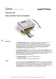
Beim statischen Wärmezähler <strong>Superstatic</strong> handelt es sich um ein Kompaktgerät.<br />
Es besteht aus den folgenden drei Teilgeräten:<br />
- Schwingstrahl Durchflusssensor<br />
- Rechenwerk Supercal<br />
- Temperaturfühler (2- oder 4-Leitertechnik) mit oder ohne Tauchhülsen<br />
General<br />
The static flow sensor and the integrator may only be operated within the<br />
conditions outlined on the identification plate, as well as within the technical<br />
specification! In case of ignoring these default conditions, the manufacturer’s<br />
responsibility is void.<br />
The manufacturer is not liable for inappropriate installation and operation.<br />
Seals may not be removed and/or only by authorized persons. The countryspecific,<br />
local regulations, as well as the manufacturer instructions must be<br />
respected!<br />
If the manufacturer’s seal has been broken or damaged, the manufacturer<br />
cannot be made responsible for the change of the verified and measuring<br />
relevant data.<br />
When using several heat meters in an installation unit, one should select, in<br />
the interest of a at most possible fair heat consumption measurement, the<br />
same types of device and installation positions.<br />
Before installation<br />
- Check the design layout data of the installation.<br />
- The pulse value and the installation location of the flow sensor must<br />
match the values indicated on the integrator, consult the identification<br />
plate!<br />
- The permissible ambient temperature range of the integrator is 5 - 55 ºC.<br />
- The installation and project prescriptions must be followed.<br />
- The readability of the integrator and also the identification plates must be<br />
followed.<br />
Remarks on the correct meter installation:<br />
Conditions to comply with the directive<br />
2004/22/EU (MID) and correct mounting positions<br />
see page 12<br />
- The integrator is by default parameterized for installation into the return<br />
flow. Special parameterization is necessary for installation in the supply<br />
flow and this must be specified with the order.<br />
- The cable between the flow sensor and the integrator must not be extended<br />
or shorted. The cable is be sealed.<br />
- All wiring must be installed with a minimum distance of 300 mm from<br />
heavy voltage and high frequency cables.<br />
- Radiated heat and interfering electrical fields close to the integrator must<br />
be avoided.<br />
- In general, the integrator should be installed away from the cooling pipes.<br />
- It has to be ensured that no condensed water can run along the wires into<br />
the calculator.<br />
- If the danger of vibrations in the piping system exists, the integrator should<br />
be installed separately on the wall.<br />
- The flow sensor should be installed between two shut-off valves.<br />
- The flow sensor must be mounted with the measuring head to the side<br />
(see page 12).<br />
- The flow direction of the flow sensor must be respected (arrow on the flow<br />
sensor).<br />
- Flush the pipe system before installing the flow sensors to guarantee that<br />
no foreign particles remain in the pipe.<br />
- The flow sensor shall be mounted BEFORE any control valve to<br />
exclude any potential parasitic influences.<br />
- During commissioning the pipe system must be purged. Air in the system<br />
of the flow sensor may affect the measurement..<br />
- Use only new and appropriate sealing material.<br />
- Water tightness of the different connections should be verified.<br />
- A lightning protection cannot be ensured; this protection has to be guaranteed<br />
by the house installation.<br />
The static heat meter <strong>Superstatic</strong> is a compact unit and consists of the following<br />
three partial units:<br />
- Fluid oscillator of flow sensor<br />
- Integrator<br />
- Temperature sensors (2- or 4-wire) with or without pockets<br />
Die Impulswertigkeit des Rechenwerks und des Durchflusssensors<br />
sowie der Widerstand der Temperaturfühler und Rechenwerk müssen<br />
aufeinander abgestimmt sein. Etiketten der Geräte vergleichen!<br />
The pulse values of the integrator and of the flow unit, as well as the<br />
resistance value of the temperature sensors and the integrator are<br />
matched one to the other. Compare the labels of the Devices!<br />
0<strong>449</strong>P300 Installation <strong>Superstatic</strong> <strong>449</strong> DE EN 28-01-2013 1 <strong>Sontex</strong> <strong>SA</strong>, 2605 Sonceboz, Schweiz, Switzerland
Kabelanschlüsse<br />
Zum Anschluss der Ein- und Ausgänge ist das Oberteil des Rechenwerks zu<br />
entfernen. Die Anschlüsse sind wie folgt vorzunehmen:<br />
Klemme Anschlussart<br />
1,2 Direktanschluss 2-Leitertechnik, Temperatur hoch<br />
1,2 und 5,6 4-Leitertechnik, Temperatur hoch<br />
3,4 Direktanschluss 2-Leitertechnik, Temperatur tief<br />
3,4 und 7,8 4-Leitertechnik, Temperatur tief<br />
10 (+) Impulseingang Durchflusssensor <strong>449</strong> (weisses Kabel)<br />
11 (-) Impulseingang Durchflusssensor <strong>449</strong> (grünes Kabel)<br />
9 Spannungsversorgung Durchflusssensor <strong>449</strong> (braunes<br />
Kabel)<br />
50 (+) Impulseingang zusätzlicher Impulseingang 1<br />
51 (-) Impulseingang zusätzlicher Impulseingang 1<br />
52 (+) Impulseingang zusätzlicher Impulseingang 2<br />
53 (-) Impulseingang zusätzlicher Impulseingang 2<br />
16 (+) Open collector-Ausgang 1<br />
17 (-) Open collector-Ausgang 1 + 2<br />
18 (+) Open collector-Ausgang 2<br />
24 M-Bus (Optionales oder ab Werk bestücktes Modul)<br />
25 M-Bus (Optionales oder ab Werk bestücktes Modul)<br />
Klemmen 1 (5) und 2 (6) für Temperaturen hoch<br />
Klemmen 3 (7) und 4 (8) für Temperaturen tief<br />
Anschlussschema Temperaturfühler und<br />
korrekte Einbaulagen s. Seite 4 und 12.<br />
Cable connection<br />
To connect the inputs and outputs the integrator’s upper part must be removed..<br />
The connections are to be made as follows:<br />
Terminal connection type<br />
1,2 2-wire direct connection, temperature high<br />
1,2 and 5,6 4-wire, temperature high<br />
3,4 2-wire direct connection, temperature low<br />
3,4 and 7,8 4-wire, temperature low<br />
10 (+) pulse inputs flow sensor <strong>449</strong> (white cable)<br />
11 (-) pulse inputs flow sensor <strong>449</strong> (green cable)<br />
9 supply voltage for the flow sensor <strong>449</strong> (brown cable)<br />
50 (+) Pulse input, additional pulse input 1<br />
51 (-) Pulse input, additional pulse input 1<br />
52 (+) Pulse input, additional pulse input 2<br />
53 (-) Pulse input, additional pulse input 2<br />
16 (+) Open collector-output 1<br />
17 (-) Open collector output 1 + 2<br />
18 (+) Open collector output 2<br />
24 M-Bus (module optional or equipped at factory)<br />
25 M-Bus (module optional or equipped at factory)<br />
Terminals 1 (5) and 2 (6) for temperatures high<br />
Terminals 3 (7) and 4 (8) for temperatures low<br />
Temperature sensors connections and correct mounting<br />
positions see page 4 and 12.<br />
Achtung: Die geschirmten Kabel müssen generell mit<br />
der Zugentlastung geerdet werden! (sehe Bild auf Seite 12)<br />
Erdung<br />
Es ist darauf zu achten, dass sämtliche Erdungsanschlusspunkte<br />
(Leitungsnetz, externe Speisung und Chassis vom Durchflusssensor) der<br />
Gesamtinstallation äquipotenzial sind.<br />
Spannungsversorgungsmodule<br />
Die Spannungsversorgungsmodule werden mittels einer Steckverbindung an<br />
die Hauptanschlussplatine angeschlossen.<br />
Netzmodule<br />
Das Netzmodul 230V – 45/60 Hz ist mit einer 1A-Sicherung installationsseitig<br />
abzusichern. Die Netzmodule 230V AC, 24 VAC oder 12 – 24 VDC<br />
sind mit einer Backupbatterie bestückt. Mit der Notstromversorgung über die<br />
Backupbatterie arbeitet das Rechenwerk in einem batterie-schonenden<br />
Modus. Die messtechnischen Eigenschaften sind gewährleistet. Die<br />
Kommunikationsoptionen werden nicht unterstützt.<br />
Die Netzmodule sind ab Werk mit einem Jumper versehen. Dieser<br />
Jumper erlaubt das Aktivieren oder Deaktivieren der Backupbatterie. Im<br />
Auslieferungszustand ist der Jumper immer gesteckt, die<br />
Backupbatterie aktiviert. Auf Anfrage können die Netzmodule auch<br />
ohne Jumper geliefert werden.<br />
Note: Generally, the shielded cables must be grounded with a strain<br />
relief! (see picture on page 12)<br />
Grounding<br />
It has to be guarantied that all grounding connections (line and power mains<br />
and chassis of the flow sensor) of the total installation are equipotential.<br />
Power supply modules<br />
The power supply modules are connected by means of a plug-in connector<br />
to the main board.<br />
Mains power supply modules<br />
From the installation side, the main power 230V – 45/60 Hz is to be protected<br />
with a 1A fuse. The power supply module 230V AC, 24 VAC or12 - 24<br />
VDC are equipped at the factory with a backup battery. With the emergency<br />
power supply via the backup battery, the integrator is operated in a mode to<br />
preserve the battery. The instrumentation characteristics are ensured, however<br />
the communication options are not supported.<br />
The mains power supply modules are provided ex factory with a<br />
jumper. This Jumper permits an activating or a deactivating of the<br />
backup battery. At the delivery of the integrator the jumper is always<br />
plugged, the battery activated. Per request the power supply module<br />
can also be supplied without the jumper.<br />
Der elektrische Anschluss der Netzmodule<br />
Der elektrische Anschluss ist gemäß gültigen Normen und unter<br />
Berücksichtigung lokaler Sicherheitsvorschriften von einer autorisierten<br />
Person auszuführen. Die elektrische Netzleitung ist so zu verlegen, dass<br />
keine heißen Teile (Rohre etc. über 80°C) berührt werden können (Gefahr<br />
bei beschädigter Isolation). Die elektrischen Anschlüsse dürfen nicht mit<br />
Wasser in Berührung kommen.<br />
Backupbatterie für Datum und Uhrzeit<br />
Das eich- und messrelevante Rechenwerkoberteil ist mit einer Knopf-<br />
Zellenbatterie bestückt. Sie dient als Notstromversorgung für das Datum und<br />
die Zeit sowie die LCD-Anzeige, wenn das Rechenwerkoberteil vom<br />
Rechenwerkunterteil entfernt wird. Auf der LCD-Anzeige wird in diesem Fall<br />
die kumulierte Betriebsdauer der Batterie in Minuten angezeigt. Die<br />
Backupfunktion der Knopfzellenbatterie ist bis zu 3 Monate ausgelegt, d.h.<br />
kumulierte Zeit wo das Rechenwerkoberteil vom Rechenwerkunterteil<br />
getrennt ist.<br />
Achtung: Bei fehlendem Spannungsversorgungsmodul im Rechenwerkunterteil<br />
wird die Knopfzellenbatterie im Rechenwerkoberteil vorzeitig<br />
entleert.<br />
Bei Lagerhaltung des Rechenwerks über längere Zeit soll darauf<br />
geachtet werden, dass die Backupbatterie im mess- und eichrelevanten<br />
Rechenwerkoberteil nicht aktiviert ist. Auf Anfrage kann im Werk ein<br />
Schutzfilm montiert werden, der die Batterie vor der frühzeitigen<br />
Entladung schützt. Es ist sicher zu stellen, dass der Schutzfilm vor der<br />
Inbetriebnahme entfernt wird.<br />
The electrical connection of the mains power supply modules<br />
The electrical connection has to be done in accordance with valid standards,<br />
under consideration of local safety regulations and by an authorized person.<br />
The electrical main is to be made in such way that no hot parts (pipes etc.<br />
over 80°C) can be touched (danger with damaged isolation). Water contact<br />
of the electrical connection must be avoided.<br />
Backup battery for date and time<br />
The calibration and measuring relevant integrator upper part is equipped with<br />
a button cell battery. This button cell battery serves as power supply for the<br />
date and time function as well as for the LCD display, if the integrator upper<br />
part is removed from the lower part. On the LCD display appears in this case<br />
the cumulated running time of the battery in minutes. The back up button cell<br />
battery suffices for up to 3 months cumulated time where the upper part is<br />
separated from the lower part.<br />
Note: With missing voltage supply module from the lower part of integrator<br />
the button cell battery in the upper part of the integrator is emptied prematurely.<br />
With the storage of the integrator make sure that the back-up battery is<br />
not activated. On request a protective film can be installed at the factory,<br />
in order to protect the battery from an early discharge. Make sure<br />
to remove the protective film before commissioning.<br />
0<strong>449</strong>P300 Installation <strong>Superstatic</strong> <strong>449</strong> DE EN 28-01-2013 2 <strong>Sontex</strong> <strong>SA</strong>, 2605 Sonceboz, Schweiz, Switzerland
Sicherheitshinweise<br />
Das Rechenwerk ist gemäß EN 61010 Schutzmaßnahmen für elektronische<br />
Messgeräte gefertigt und geprüft und hat das Werk in sicherheitstechnisch<br />
einwandfreiem Zustand verlassen. Zur Erhaltung dieses Zustands und zum<br />
gefahrlosen Betreiben des Rechenwerks muss der Anwender die Hinweise<br />
und Warnvermerke beachten, die in der Installationsanleitung enthalten sind.<br />
Beim Öffnen von Abdeckungen oder Entfernen von Teilen, außer wenn dies<br />
von Hand möglich ist, können spannungsführende Teile freigelegt werden.<br />
Weiterhin können Anschlussstellen spannungsführend sein. Sämtliche<br />
Reparaturen- und Wartungsarbeiten dürfen nur von einer hierfür<br />
ausgebildeten und befugten Fachkraft ausgeführt werden. Weisen Gehäuse<br />
und / oder Anschlusskabel Beschädigungen auf, so ist das Rechenwerk<br />
außer Betrieb zu setzen und gegen versehentliche Wiederinbetriebnahme zu<br />
sichern. Vermeiden Sie generell eine Einbausituation mit einem<br />
überdurchschnittlichen Wärmestau. Ein überdurchschnittlicher Wärmestau<br />
beeinflusst massiv die Lebenszeit der elektronischen Bauteile.<br />
Wärmezähler sind Messgeräte und sorgsam zu behandeln. Zum Schutz vor<br />
Beschädigung und Verschmutzung sollte die Verpackung erst unmittelbar vor<br />
dem Einbau entfernt werden.<br />
Zur Reinigung ist ausschließlich ein mit Wasser befeuchtetes Tuch zu<br />
verwenden, keine Lösungsmittel.<br />
Die Anschluss- und Verbindungskabel dürfen nicht an der Rohrleitung<br />
befestigt und keinesfalls mit isoliert werden.<br />
Funktionskontrolle<br />
Nach dem Öffnen der Absperrorgane ist die Installation auf die Dichtigkeit zu<br />
prüfen. Durch wiederholtes Drücken der orangen Bedientaste können auf der<br />
LCD-Anzeige des Rechenwerkes diverse Betriebsparameter z.B. Durchfluss,<br />
Leistung, sowie Vor- und Rücklauftemperatur abgelesen werden. Der Kommunikationsindikator<br />
auf der LCD-Anzeige dient zur Überprüfung des Kommunikations-Input<br />
oder -Output. Mit der Software Prog<strong>449</strong> können zudem die<br />
Kommunikationsausgänge simuliert werden. Der Durchfluss kann mit Hilfe<br />
des Durchflussindikators geprüft werden. Die Dynamik des Durchflusssensors<br />
kann mit Hilfe der aktuellen Durchflussanzeige in Verbindung mit einer<br />
Durchflussregelung überprüft werden.<br />
Sämtliche Parameteranzeigen dienen zur Kontrolle des Zählers bzw. zur<br />
Einregulierung der Anlage. Es ist zu überprüfen, dass der einregulierte<br />
Durchfluss der Anlage den maximal erlaubten Durchfluss des Zählers<br />
nicht überschreitet. Zur umfassenden Funktionsprüfung wird ein<br />
Inbetriebnahmeprotokoll über die optische Schnittstelle mit der<br />
Auslese-Software empfohlen.<br />
Druckverlustkurve<br />
Safety instructions<br />
The integrator is manufactured and tested according to EN 61010 safety<br />
control for measuring units and left the factory in perfect safety technical<br />
condition. To maintain this status and to guarantee safe operation of the<br />
integrator, the user must respect the instructions contained in this document.<br />
When opening covers or removing parts, parts under power can be accessed.<br />
Further connection terminals can be under power. All repair and<br />
maintenance work may be only implemented by a trained and an authorized<br />
specialist. If the housings and/or the connecting cable show any damage, the<br />
integrator unit should be disconnected and secured against accidentally<br />
reset up – put in operation. Generally, avoid an installation situation with an<br />
accumulation of heat above average. An above average heat buildup affects<br />
substantially the lifetime of the electronic components.<br />
Heat meters are measuring devices and must be handled with care.<br />
To protect the unit against damage and contamination, the packing should<br />
be only removed at the moment of installation.<br />
For cleaning just use water moistened cloth and no solvent.<br />
The connecting and connection cable may not be fastened on the pipe and<br />
under no circumstances be isolated together with the pipe.<br />
Function test<br />
After opening the shutoff devices the installation must to be examined for<br />
any leakage. By repeated pressing of the orange user button, various operating<br />
parameters e.g. flow, power, as well as supply and return temperature<br />
can be read from the LCD display of the integrator unit. The communication<br />
indicator on the LCD display serves for the test of the communication input<br />
or output. With the software Prog<strong>449</strong> the communication outputs can be<br />
simulated. The flow can be tested with the help of the flow indicator. The<br />
dynamics of the flow measurement can be tested with the help of the current<br />
flow display in connection with a flow control.<br />
Several displayed parameters serve to control the meters and/or to<br />
adjust the installation. It has to be verified that the established flow of<br />
the system does not exceed the maximum permitted flow of the meter.<br />
For a comprehensive functional analysis, it is recommended to read<br />
the startup protocol by means of the optical interface and reading<br />
software<br />
Pressure Loss Curve<br />
0<strong>449</strong>P300 Installation <strong>Superstatic</strong> <strong>449</strong> DE EN 28-01-2013 3 <strong>Sontex</strong> <strong>SA</strong>, 2605 Sonceboz, Schweiz, Switzerland
45°<br />
Temperaturfühlermontage<br />
Die auf dem Typenschild der Temperaturfühler angegebenen Temperaturen<br />
sind zu beachten. Die Temperaturfühler sind immer gepaart abgestimmt.<br />
Sie werden nur gepaart geliefert und dürfen nicht getrennt, verlängert<br />
oder gekürzt werden, da dies die Messgenauigkeit beeinflusst. Bei<br />
Temperaturfühlerpaaren mit einer Kabellänge länger als 3 m, empfehlen<br />
wir ausschließlich den Einsatz von geschirmten Temperaturfühlerpaaren. In<br />
diesem Fall muss die Abschirmung korrekt angelegt werden. Temperaturfühler<br />
mit Tauchhülsen müssen bis zum Anschlag eingeführt werden –<br />
anschließend fixieren. Bei ungleichen Kabellängen oder länger 6 m empfehlen<br />
wir ausschliesslich die Vierleitertechnik. Die Temperaturfühler können<br />
wahlweise in Tauchhülsen oder direkt ins Heizungs- bzw. Kühlmedium<br />
montiert werden beide aber immer gleich. Eine asymmetrische Montage,<br />
ein Fühler direkt und der andere mit Tauchhülse, ist NICHT zulässig.<br />
Der messaktive Bereich der Temperaturfühlerspitze muss sich in der Mitte<br />
des Rohrleitungsquerschnitts befinden.<br />
Temperature sensors mounting<br />
The temperatures indicated on the identification plate of the temperature<br />
sensors are to be observed. The temperature sensors are always paired.<br />
Only matched pairs are supplied and may not be separated, extended or<br />
shortened, since this affects the measuring accuracy. With temperature<br />
sensor pairs with a cable length longer than 3 m, we exclusively recommend<br />
the use of shielded temperature sensor pairs. In this case, the<br />
shields must be installed correctly. Temperature sensors with protection<br />
pockets must be inserted up to the stall – and fixed afterwards. With unequal<br />
cable lengths or longer than 6 m we recommend exclusively the use of<br />
four-wire technology. The temperature sensors can be installed alternatively<br />
in protection pockets or directly in the heating and/or cooling agent however<br />
always both in the same way. Asymmetrical mounting, one sensor<br />
direct the other with pockets, is NOT permitted The measuring tip of the<br />
temperature sensor part must be positioned in the center of the cross<br />
section of the pipe<br />
DN15, 20, 25<br />
Einbau im T-Stück<br />
Installation in T-fitting<br />
< DN 50<br />
Einbau in Schweissmuffe 90°<br />
Installation with welding sleeve 90°<br />
< DN 50<br />
Einbau in Schweissmuffe 45°<br />
Installation with welding sleeve 45°<br />
Temperaturfühler senkrecht zur Achse der<br />
Rohrleitung in der selben Ebene<br />
Temperature sensor perpendicularly to the axis<br />
of the piping in the same level<br />
Temperaturfühlerachse übereinstimmend mit der<br />
Rohrachse<br />
Temperature sensor axle coincide with the tubing<br />
axle<br />
Temperaturfühlermesselement eingetaucht in die<br />
Rohrachse<br />
Temperature sensor measuring element submerged<br />
onto the tubing axle<br />
Zuordnungsliste Tauchhülsen / Allocation list sensor pockets<br />
Temperaturfühler Versionen Tauchhülse Artikelnummer<br />
Temperaturbereich<br />
Material<br />
Temperature sensor Versions Pocket Part number Temperature range<br />
Ø 6x31mm Pt100, Pt500 G3/8" 0460A202 Messing/Brass 0…100 °C<br />
Ø 6x31mm Pt100, Pt500 G1/2" 0460A206 Messing/Brass 0…100 °C<br />
Anschlussschema Temperaturfühler / Temperature sensors connections<br />
2-Leiter Kabelfühler / 2 wire cable sensor<br />
1 / 2 Temperatur hoch / temperature high<br />
3 / 4 Temperatur tief / temperature low<br />
4-Leiter Fühler mit 2-Leiter Rechenwerk<br />
4 wire sensor with 2 wire integrator<br />
1 / 2 Temperatur hoch / temperature high<br />
3 / 4 Temperatur tief / temperature low<br />
4-Leiter Fühler mit 4-Leiter Rechenwerk<br />
4 wire sensor with 4 wire integrator<br />
1 / 5 + 2/ 6 Temperatur hoch / temperature high<br />
3 / 7 + 4/ 8 Temperatur tief / temperature low<br />
Kabelquerschnitte für Kopffühler ≥ 0,5 mm 2 (EN 1434-2) / Wire cross section for head sensors ≥ 0,5 mm 2 (EN 1434-2)<br />
Temperaturfühlereinbau bei Kälteanlagen<br />
Temperature sensor installation with cooling applications<br />
Die Isolation darf nur bis zur Temperaturfühlerverschraubung<br />
vorgenommen werden.<br />
The isolation may be made only up to the temperature<br />
sensor screw connection.<br />
Die Verschraubung der Temperaturfühler darf auf keinen<br />
Fall mit isoliert werden. Dies gilt auch, wenn der Temperaturfühler<br />
direkt im Durchflusssensor montiert ist.<br />
The screw connection of the temperature sensors may<br />
in no case be isolated with. This applies even if the<br />
temperature sensor is installed directly in the flow sensor.<br />
0<strong>449</strong>P300 Installation <strong>Superstatic</strong> <strong>449</strong> DE EN 28-01-2013 4 <strong>Sontex</strong> <strong>SA</strong>, 2605 Sonceboz, Schweiz, Switzerland
Fehlermeldungen<br />
Das Rechenwerk Supercal zeigt auf der LCD-Anzeige mit der Bezeichnung<br />
Err und einem Zahlencode die anliegenden Fehlermeldungen an. Wenn<br />
mehrere Fehler gleichzeitig anliegen, werden die Nummern der Fehlermeldungen<br />
summiert.<br />
Err1<br />
Err2<br />
Der Vorlauffühler hat einen Kurzschluss oder Unterbruch<br />
Der Rücklauffühler hat einen Kurzschluss oder Unterbruch<br />
Temperaturfühler vertauscht bzw. Temperaturfühler im<br />
kälteren Strang ist höher als im wärmeren Strang<br />
Err4 Durchfluss zu hoch<br />
Err8 Speicherfehler EEPROM im mess- und eichrelevanten Teil<br />
(erst nach dem zweiten mal aktiv)<br />
Err16 Speicherfehler EEPROM im Rechenwerkunterteil<br />
(erst nach dem zweiten mal aktiv)<br />
Err32 Konfigurationsfehler EEPROM im mess- und eichrelevanten Teil<br />
Err64 Konfigurationsfehler EEPROM im Rechenwerkunterteil<br />
Err128 Interner Elektronikfehler, zurück zum Hersteller<br />
Err256 Spannungsausfall (bei Netz- oder Busversorgung)<br />
Err512 Defektes Kommunikationsmodul Steckplatz 1<br />
Err1024 Defektes Kommunikationsmodul Steckplatz 2<br />
Err2048 Fehler Impulseingang Zusatzzähler A1<br />
Err4096 Fehler Impulseingang Zusatzzähler A2<br />
Err8192 Interner Elektronikfehler, zurück zum Hersteller<br />
Liegt ein Fehler mehr als eine Stunde an, so wird er im Fehlerspeicher mit<br />
Datum und Uhrzeit (Fehleranfang) und Dauer (in Minuten) abgespeichert.<br />
Wenn ein Fehler weniger als 60 Minuten anliegt, so wird er automatisch und<br />
ohne Speicherung gelöscht.<br />
Die zwei Temperaturfühlerindikatoren werden bei der kumulierten Energieanzeige<br />
auf dem Hauptmenü angezeigt, wenn:<br />
- die Temperaturfühler vertauscht sind dieser Anlagenzustand tritt bei den<br />
meisten Installationen während der Sommerzeit auf<br />
- die Temperatur im kälteren Strang höher ist als im wärmeren Strang.<br />
Sämtliche Fehlermeldungen werden 60 Sekunden nach der Fehler-<br />
Beseitigung automatisch auf der LCD-Anzeige gelöscht.<br />
Optionale Kommunikationsmodule<br />
Das Rechenwerk kann mit bis zu zwei verschiedenen optionalen Kommunikationsmodulen<br />
nachgerüstet werden. Die optionalen Kommunikationsmodule<br />
können nachbestückt werden, ohne dass die eichamtliche Prüfung<br />
verletzt wird. Die Optionsmodule sind rückwirkungsfrei auf den eichrelevanten<br />
Teil im Rechenwerkdeckel. Spätestens 10 Sekunden nach der Montage<br />
erkennt das Rechenwerk die eingesteckten Optionsmodule und ist für die<br />
Funktionen frei verfügbar. Beim Anschluss der Kommunikationsmodule ist<br />
die mitgelieferte Installationsanleitung zu beachten.<br />
Parametrierungen<br />
Durch setzen eines Jumpers auf der Hauptplatine auf dem Steckplatz JP1<br />
wird der Parametrier- und Testbetrieb aktiviert. Über die 2 Bedientasten auf<br />
dem Rechenwerk können Datum und Zeit, Kundennummer und die M-Bus<br />
Primäradresse geändert werden. Der Stromverbrauch ist im Parametrierund<br />
Testbetrieb grösser als im Normalbetrieb, also Jumper unbedingt wieder<br />
entfernen nach Abschluss der Parametrierungen.<br />
Weitere Parameter können mit der Software Prog<strong>449</strong> geändert werden<br />
abhängig von den Berechtigungen und ohne Setzen des Jumpers.<br />
Kühlmittel (Glykol)<br />
Im Rechenwerk <strong>Superstatic</strong> <strong>449</strong> sind mehr als 40 Kühlmittel fest programmiert<br />
und eine Vielzahl von weiteren Mischungen können per Software<br />
definiert werden.<br />
Wird die Funktion Kühlmittel (Glykol)-Wassergemisch verwendet, d.h. ein<br />
Kühlmittelgemisch aus dem Menü der SW Prog<strong>449</strong> ist angewählt, wird dies<br />
im Hauptmenü der LCD mit einem „Y“(YES) auf der 1. LCD Position angezeigt<br />
(Symbol L: Liquid): Letzte Position im Hauptmenü vor dem Segmenttest,<br />
siehe Seite 7.<br />
Error messages<br />
The integrator indicates occurring errors by displaying on the LCD the Errsign<br />
together with a numbered code. If several errors occur at the same<br />
time, the numbers of the error codes are added.<br />
Err1 The supply sensor is short circuited or disconnected<br />
Err2 The return sensor is short circuited or disconnected<br />
The temperature sensors are switched; the temperature sensor in the<br />
cooler line is higher than the temperature sensor in the warmer line<br />
Err4 Flow rate too high<br />
Err8 EEPROM error in the integrator base<br />
(only active after the second incident)<br />
Err16 EEPROM error in the measurement and calibration part<br />
(only active after the second incident)<br />
Err32 Configuration error into the measurement and calibration part<br />
Err64 Configuration error into the integrator base<br />
Err128 Internal electronic failure, return to manufacturer<br />
Err256 Tension drop (by mains supply or bus supply)<br />
Err512 Defective communication module connection place 1<br />
Err1024 Defective communication module connection place 2<br />
Err2048 Error pulse inputs additional meter A1<br />
Err4096 Error pulse inputs additional meter A2<br />
Err8192 Internal electronic failure, return to manufacturer<br />
If an error lasts longer than an hour the error will be registered in the error<br />
register with its date and time (beginning) and duration (in minutes). When<br />
an error lasts less than 60 minutes the error will be automatically deleted<br />
without being memorized.<br />
The two temperature indicators are displayed on the cumulated energy<br />
by the main menu when:<br />
- Temperature sensors are switched this installation error mode happen<br />
with most installations during the summer time<br />
- Temperature in the cooler line is higher than the one in the warmer line.<br />
These error messages are automatically deleted from the LCD display 60<br />
seconds after the error has been removed.<br />
Communication options<br />
The integrator can be fitted with up to two different optional communication<br />
modules. The optional communication modules can be equipped afterwards,<br />
without damaging the verification. The optional modules have no<br />
influence on the verified relevant part in the cover of the integrator unit. At<br />
the latest 10 seconds after the installation, the integrator unit recognizes<br />
the plugged in optional modules and the functions are freely available.<br />
When connecting the communication modules, the installation guidance -<br />
supplied with the unit - is to be considered.<br />
Parameter mode<br />
By plugging a jumper on the main board, position JP1, the parameter and<br />
test mode is activated. With the 2 buttons on the integrator date and time,<br />
customer number and the M-Bus primary address can be modified. The<br />
current consumption is higher with the parameter and test mode than in the<br />
normal mode, thus it’s important to remove the jumper after the parameterisation.<br />
Additional parameters can be modified with the software Prog<strong>449</strong> depending<br />
on the user rights but without plugging the jumper.<br />
Cooling liquids (Glycols)<br />
In the integrator <strong>Superstatic</strong> <strong>449</strong> more than 40 cooling liquids are programmed<br />
and many additional mixtures can be specified per software.<br />
If the feature cooling liquid (Glycol) water mixture is enabled with the SW<br />
Prog<strong>449</strong>, this means a liquid is selected from the software menu; it’s also<br />
displayed in the LCD main menu and indicated with a “Y” (YES) on the 1 st<br />
LCD position (symbol L: Liquid): Last position in the main menu before the<br />
segment test, see page 7.<br />
0<strong>449</strong>P300 Installation <strong>Superstatic</strong> <strong>449</strong> DE EN 28-01-2013 5 <strong>Sontex</strong> <strong>SA</strong>, 2605 Sonceboz, Schweiz, Switzerland
Anzeige<br />
Das Rechenwerk verfügt über folgende Anzeigeebenen: siehe Etikette<br />
unterhalb der Anzeige<br />
- Favoritenmenü (sofern aktiviert)<br />
- Hauptmenü (Abrechnungsrelevante Daten)<br />
- Stichtage<br />
- Monatswerte<br />
- Mittelwerte<br />
- Maximalwerte<br />
- Konfiguration<br />
- Service<br />
Die Anzeigeebenen können kundenspezifisch in der Anzahl sowie in der<br />
Reihenfolge der Anzeigesequenzen parametriert werden. Aus diesem<br />
Grund können Abweichungen im Bereich der Anzeigeebenen und der Reihenfolge<br />
der Anzeigesequenzen möglich sein.<br />
LCD-Bedienkonzept<br />
Mit der Pfeiltaste können Sie die verschiedenen Menüs oder<br />
die Positionen innerhalb der Menüs ansteuern. Im Prüfbetrieb<br />
können Sie auch die Zahlen von 0...9 mit der Pfeiltaste erhöhen.<br />
Durch Drücken der Entertaste können Sie das Menü oder die<br />
Position bestätigen.<br />
Wenn Sie die Entertaste gedrückt halten (beliebige Position<br />
und/oder Menü), können Sie durch Drücken der Pfeiltaste auf<br />
die verschiedenen Ebenen zurückkehren oder durch gleich<br />
zeitiges Drücken der Entertaste und Pfeiltaste kehren Sie auf<br />
die vorherige Menüposition zurück.<br />
Nach 3 Minuten schaltet die Anzeige des Rechenwerkes automatisch auf<br />
das Hauptmenü zurück.<br />
Display<br />
The integrator Supercal has the following display sequence:<br />
See label below the display<br />
- Favorite menu (if activated)<br />
- Main menu (Billing relevant data)<br />
- Set days<br />
- Monthly values<br />
- Average values<br />
- Maximal values<br />
- Configuration<br />
- Service<br />
The display levels can be customized; in number and in order of the display<br />
sequences. For this reason deviations can be possible in the range of the<br />
display levels and the order of the display sequences.<br />
LCD control concept<br />
With the arrow key you can address the different menus or the<br />
positions within a menu. In the verification mode you can also<br />
increment with the arrow key the digits from 0...9.<br />
By pressing the enter key you can confirm the menu or the<br />
position.<br />
When you keep pressing the enter key, you can by pressing<br />
the arrow key (at any Pos. and/or menu) get back to the different<br />
levels or by simultaneously pressing the enter key and the arrow<br />
key you can get back to the previous menu position.<br />
After 3 minutes the display of the integrator switches automatically back to<br />
the main menu.<br />
LCD (Liquid Crystal Display)<br />
Maximalwerte<br />
Maximum values<br />
Mittelwerte<br />
Average values<br />
Tarif 1 und Tarif 2<br />
Tariff 1 and tariff 2<br />
Werte ändern<br />
Edit Values<br />
Temperatur hoch<br />
Temperature high<br />
Indikator Messung Energie<br />
Indication measurement energy<br />
Temperatur tief<br />
Temperature low<br />
Ausgangskommunikation<br />
Output communication<br />
Eingangskommunikation<br />
Input communication<br />
Durchflussindikator<br />
Flow indication<br />
Index für die Monats-, Mittel- und<br />
Maximalwerte<br />
Index for the monthly, average<br />
and maximum values<br />
Einheiten<br />
Units<br />
Anzeigeziffern<br />
Display figures<br />
Rahmen Nachkommastellen<br />
Frame for decimal figures<br />
Index für die Menüführung<br />
Index for menu guidance<br />
<br />
1 2 3 4 5 6 7<br />
Statischer Wärmezähler Supestatic <strong>449</strong><br />
Static Heat Meter <strong>Superstatic</strong> <strong>449</strong><br />
0<strong>449</strong>P300 Installation <strong>Superstatic</strong> <strong>449</strong> DE EN 28-01-2013 6 <strong>Sontex</strong> <strong>SA</strong>, 2605 Sonceboz, Schweiz, Switzerland
Haupmenü Stichtagsmenü Monatswerte<br />
Main menu Set day menu Monthly values<br />
000432i.0<br />
S i<br />
D A<br />
0i.07.2005<br />
S 2<br />
0i.0i.2006<br />
D A<br />
01<br />
0i.--.----<br />
D A<br />
1 2 3 4 5 6 7<br />
Kumulierte Energie<br />
Cumulated energy<br />
M 3<br />
000382.00<br />
Kumuliertes Volumen<br />
Cumulated volume<br />
000i38i.0<br />
Kumulierte Energie Tarif 1<br />
Cumulated energy tariff 1<br />
M 3<br />
000382.00<br />
Kumuliertes Volumen Tarif1<br />
Cumulated volume tariff 1<br />
1 2 3 4 5 6 7<br />
Datum Stichtag 1<br />
Date set day 1<br />
S i<br />
000432i.0<br />
Energie Stichtag 1<br />
Energy set day 1<br />
S i<br />
M 3<br />
000382.00<br />
Volumen Stichtag 1<br />
Volume set day 1<br />
S i<br />
000i38i.0<br />
Energie Tarif 1 Stichtag1<br />
Energy tariff 1 set day 1<br />
S i<br />
M 3<br />
000382.00<br />
Datum Stichtag 2<br />
Date set day 2<br />
S 2<br />
000832i.0<br />
Energie Stichtag 2<br />
Energy set day 2<br />
S 2<br />
M 3<br />
00i282.00<br />
Volumen Stichtag 2<br />
Volume set day 2<br />
S 2<br />
000i87i.0<br />
Energie Tarif 1 Stichtag2<br />
Energy tariff 1 set day 2<br />
S 2<br />
M 3<br />
000562.00<br />
1 2 3 4 5 6 7<br />
Speichertag Monatswerte<br />
Storage day mounthly values<br />
01<br />
000832i.0<br />
Letzter Monastwert Energie<br />
Last monthly value energy<br />
01<br />
M 3<br />
000782.00<br />
Letzter Monatswert Volumen<br />
Last monthly value volume<br />
01<br />
000232i.0<br />
Letzter Monatsw. Energie Tarif 1<br />
Last monthly value energy tariff 1<br />
01<br />
M 3<br />
000382.00<br />
02<br />
00i872i.0<br />
Energie vor einem Monat<br />
Energy one month ago<br />
02<br />
M 3<br />
000862.00<br />
Volumen vor einem Monat<br />
Volume one month ago<br />
02<br />
000i32i.0<br />
Energie Tarif 1 vor einem Monat<br />
Energy tariff 1 one month ago<br />
02<br />
M 3<br />
000682.00<br />
03-15<br />
03-15<br />
03-15<br />
03-15<br />
00003i2.0<br />
Kumulierte Energie Tarif 2<br />
Cumulated energy tariff 2<br />
M 3<br />
000332.00<br />
Kumuliertes Volumen Tarif 2<br />
Cumulated volumen tariff 2<br />
A I<br />
000002.10<br />
Kum. Wert Impulseingang 1<br />
Cum value pulse input 1<br />
A 2<br />
003280.90<br />
Kum. Wert Impulseingang 2<br />
Cum value pulse input 2<br />
Volumen Tarif1 Stichtag1<br />
Volume tariff 1 set day1<br />
S i<br />
00003i2.0<br />
Energie Tarif 2 Stichtag 1<br />
Energy tariff 2 set day 1<br />
S i<br />
M 3<br />
000382.00<br />
Volumen Tarif2 Stichtag1<br />
Volumen tariff 2 set day1<br />
S i<br />
A I<br />
0000382i<br />
Impulseingang1 Stichtag1<br />
Pulse input 1 set day1<br />
S i<br />
A 2<br />
00328090<br />
Impulseingang 2 Stichtag 1<br />
Pulse input 2 set day1<br />
Volumen Tarif1 Stichtag 2<br />
Volume tariff 1 set day 2<br />
S 2<br />
00004i2.0<br />
Energie Tarif 2 Stichtag 2<br />
Energy tariff 2 set day 2<br />
S 2<br />
M 3<br />
001232.00<br />
Volumen Tarif 2 Stichtag2<br />
Volume tariff 2 set day 2<br />
S 2<br />
A I<br />
000053i0<br />
Impulseingang1 Stichtag2<br />
Pulse input 1 set day 2<br />
S 2<br />
A 2<br />
00648090<br />
Impulseingang 2 Stichtag 2<br />
Pulse input 2 set day 2<br />
Letzter Monatsw. Volumen Tarif 1<br />
Last monthly value volume tariff 1<br />
01<br />
Letzter Monatsw. . Energie Tarif 2<br />
Last monthly value energy tariff 2<br />
01<br />
M 3<br />
01<br />
A I<br />
Letzter Monatsw. Impulseingang1<br />
Last monthly value pulse input 1<br />
01<br />
A2<br />
Volumen Tarif 1 vor einem Monat<br />
Volume tariff 1 one month ago<br />
00003i2.0 00003i2.0<br />
02<br />
Energie Tarif 2 vor einem Monat<br />
Energy tariff 2 one month ago<br />
02<br />
M 3<br />
000332.00 001232.00<br />
Letzter Monatsw. Volumen Tarif 2<br />
Last monthly value volume tariff 2<br />
00002i30<br />
Letzter Monatsw. Impulseingang 2<br />
Last monthly value pulse input 2<br />
Volumen Tarif 2 vor einem Monat<br />
Volume tariff 2 one month ago<br />
02<br />
A I<br />
Impulseingang 1 vor einem Monat<br />
Pulse input 1 one month ago<br />
02<br />
00i653i0<br />
000032i0 00648090<br />
A2<br />
Impulseingang 2 vor einem Monat<br />
Pulse input 2 one month ago<br />
03-15<br />
03-15<br />
03-15<br />
03-15<br />
°C<br />
80.3 20.i<br />
Temperatur hoch / tief<br />
Temperature high / low<br />
Temperaturdifferenz<br />
Temperature difference<br />
Leistung<br />
Power<br />
Durchfluss<br />
Flow<br />
60.20<br />
23.900<br />
42.355<br />
LC<br />
-y 0<br />
M 3 K<br />
Legende<br />
Legend<br />
03-32<br />
Standardanzeige<br />
Standard indication<br />
Wird nur angezeigt wenn die Option verfügbar ist<br />
Only indicated if the option is available<br />
Weitere Werte innerhalb des Menüs abrufbar:<br />
3 - 15 Monatswert<br />
3 - 32 Mittelwert<br />
3 - 32 Maximalwert<br />
Further values within the menu available:<br />
3 - 15 monthly values<br />
3 - 32 average values<br />
3 - 32 maximum values<br />
Glykol Kurve<br />
Glycol curve<br />
Einbauort<br />
Mounting position<br />
88<br />
88888.888<br />
Segmenttest<br />
Segment test<br />
0<strong>449</strong>P300 Installation <strong>Superstatic</strong> <strong>449</strong> DE EN 28-01-2013 7 <strong>Sontex</strong> <strong>SA</strong>, 2605 Sonceboz, Schweiz, Switzerland
Mittelwerte<br />
Average values<br />
Maximalwerte<br />
Maximum values<br />
Sicherungsmassnahmen<br />
Safety Measures<br />
Plombierungen<br />
Da die Plombierungen länderspezifisch unterschiedlich sein können, sind<br />
die lokalen Vorschriften zu beachten. Gegen allfällige Manipulation oder den<br />
unbefugten Ausbau müssen der Wärmezähler, die Verschraubungen sowie<br />
die Temperaturfühler und Tauchhülsen mit Benutzerplomben versehen<br />
werden. Die Plomben dürfen nur durch autorisierte Personen entfernt werden.<br />
Bei Nichtbeachtung entfällt die Gewährleistungspflicht. Es ist wichtig,<br />
dass die Plombierdrähte so kurz wie möglich ausgelegt werden und zur<br />
Plombe gut gespannt sind. Nur so ist die Plombierung gegen unbefugten<br />
Eingriff geschützt.<br />
- Empfehlung für die Plombierung - Recommendations for sealing<br />
Security seals<br />
Seals are country specific; the local regulations must be respected.<br />
Against possible manipulation or unauthorized dismantling, the heat meters,<br />
the screw connections, as well as the temperature sensors and pockets<br />
must be protected with user seals. The seals may be removed only by<br />
authorized persons. By neglecting this precaution the guarantee obligation<br />
is void. It is important that the seal wires are kept as short as possible and<br />
are well strained towards the seals. Only this way, the seal is protected<br />
against unauthorized interference.<br />
1<br />
2<br />
Ab Werk plombiert - Ex factory seals<br />
1: Klebeplombe / Sticker seal<br />
2: Drahtplombe / Wire seal<br />
Ab Werk plombiert - Ex factory seals<br />
0<strong>449</strong>P300 Installation <strong>Superstatic</strong> <strong>449</strong> DE EN 28-01-2013 8 <strong>Sontex</strong> <strong>SA</strong>, 2605 Sonceboz, Schweiz, Switzerland
Konfiguration Service Prüfprogramm<br />
Configuration Service Test mode<br />
i7.03.2006<br />
DA<br />
60525623<br />
00000000<br />
1 2 3 4 5 6 7<br />
Aktuelles Datum<br />
Actual date<br />
Aktuelle Zeit<br />
Actual time<br />
i5.02<br />
p l<br />
95.0<br />
Impulswertigkeit<br />
Pulse value<br />
a i M 3<br />
0.0i<br />
Einheit Impulseingang A1<br />
Unit pulse input A1<br />
A I<br />
i.0000<br />
Impulswertigkeit Eingang A1<br />
Pulse value input A1<br />
B I<br />
i.0000<br />
Impulswertigkeit Ausgang B1<br />
Pulse value output B1<br />
60<br />
Integrationszeit Mittelwert<br />
Integration time average value<br />
24<br />
a 2 M 3<br />
A2<br />
0.0i<br />
Einheit Impulseingang A2<br />
Unit pulse input A2<br />
i.0000<br />
Impulswertigkeit Eingang A2<br />
Pulse value input A2<br />
B2<br />
i.0000<br />
Impulswertigkeit Ausgang B2<br />
Pulse value output B2<br />
1 2 3 4 5 6 7<br />
Identifikationsnummer<br />
Identification number<br />
60525622<br />
Nummer Rechenweroberteil<br />
Number upper part integrator<br />
60525622<br />
Nummer Rechenwerkunterteil<br />
Number lower part integrator<br />
Softwareversion<br />
Software version<br />
Hardwareversion<br />
Hardware version<br />
4.i<br />
4.2<br />
00000000<br />
Impulswertigkeit Eingang A 1<br />
Pulse value input A 1<br />
500<br />
Temperaturfühler Typ<br />
Typ temperature sensor<br />
45698<br />
1 2 3 4 5 6 7<br />
Start Rechenwerkprüfung<br />
Start integrator test<br />
M 3<br />
2.0000000<br />
Volumen für die Simulation<br />
Volume for simulation<br />
0.0000<br />
Simulierte Energie<br />
Simulated energy<br />
i0.i0<br />
Temperaturdifferenz<br />
Temperature difference<br />
°C<br />
60.i2 50.02<br />
Temperatur hoch / tief<br />
Temperature high / low<br />
0.0000000<br />
M 3<br />
Simulierte Volumen<br />
Simulated volume<br />
0.0000000<br />
M3<br />
Aktueller Durchfluss<br />
Actuel flow<br />
K<br />
Integrationszeit Maximalwert<br />
Integration time maximum value<br />
Betriebsstunden<br />
Runing hours<br />
M-Busadresse<br />
M-Bus address<br />
249<br />
249<br />
Tage ohne Durchfluss<br />
Days without flow<br />
9600<br />
249<br />
M-Bus Baudrate address<br />
M-Bus baud rate<br />
Tage ohne Energie<br />
Days without energie<br />
60525623<br />
e<br />
259<br />
Funkadresse<br />
Radio address<br />
Fehlermeldung<br />
Error code<br />
34256<br />
Aktuelle Fehlerdauer in Minuten<br />
Actual duration of error in minute<br />
O i<br />
e<br />
E H<br />
259<br />
02 E H<br />
e<br />
259<br />
03 - i0<br />
Fehlermeldung<br />
Error code<br />
O i<br />
238<br />
Fehlermeldung<br />
Error code<br />
02<br />
238<br />
03 - i0<br />
Fehlerdauer in Duration of<br />
Error duration in minute<br />
O i<br />
D A<br />
28.i2.2006<br />
Fehlerdauer in Duration of<br />
Error duration in minute<br />
02<br />
28.i2.2006 D A<br />
03 - i0<br />
Startdatum Fehler 1<br />
Start date error 1<br />
O i<br />
8.i0<br />
Startdatum Fehler 1<br />
Start date error 1<br />
02<br />
8.i0<br />
03 - i0<br />
Startzeit Fehler 1<br />
Start time error 1<br />
Startzeit Fehler 2<br />
Start time error 2<br />
0<strong>449</strong>P300 Installation <strong>Superstatic</strong> <strong>449</strong> DE EN 28-01-2013 9 <strong>Sontex</strong> <strong>SA</strong>, 2605 Sonceboz, Schweiz, Switzerland
Massbilder statischer Wärmezähler <strong>Superstatic</strong> <strong>449</strong> Dimensions heat meter <strong>Superstatic</strong> <strong>449</strong><br />
Rechenwerk / Integrator<br />
Schwingstrahl Durchflusssensor / Fluid oscillator flow sensor<br />
qp G PN l (mm) H (mm) L(mm) E (mm)<br />
*0.6 m 3 /h ¾” 16 70 60 110 18<br />
1.5 m 3 /h ¾” 16 89 65 110 21<br />
1.5 m 3 /h 1” 16 89 65 130 21<br />
1.5 m 3 /h 1” 16 89 65 190 21<br />
*2.5 m 3 /h 1” 16 89 65 130 21<br />
*2.5 m 3 /h 1” 16 89 65 190 21<br />
*In Vorbereitung / under way<br />
Betriebstemperatur-Temperatur, dauernd /<br />
Operating Temperature, permanent<br />
Empfohlene Einlaufstrecken / Inlet straigt section (EN 1434)<br />
Verbindung zwischen Durchflusssensor und Rechenwerk<br />
Connection between flow sensor and integrator<br />
90°C<br />
3D für / for : L=110mm<br />
0D für / for : L=130mm<br />
0D für / for : L=190mm<br />
0.8 m; fest / fix<br />
<strong>Superstatic</strong> <strong>449</strong>: Max. 140 x 110 x 112 [mm]<br />
0<strong>449</strong>P300 Installation <strong>Superstatic</strong> <strong>449</strong> DE EN 28-01-2013 10 <strong>Sontex</strong> <strong>SA</strong>, 2605 Sonceboz, Schweiz, Switzerland
Technische Daten Durchflusssensor <strong>Superstatic</strong> <strong>449</strong> Technical Data Flow Sensor <strong>Superstatic</strong> <strong>449</strong><br />
qp<br />
Gewinde-<br />
Anschluss<br />
Ein-<br />
bau-<br />
Länge<br />
Mat.<br />
PN<br />
qp Threaded connection Length Mat. PN<br />
Maximal<br />
Durchfluss<br />
qs<br />
Maximal<br />
Durchfluss<br />
qs<br />
Minimal<br />
Durchfluss<br />
qi<br />
Minimal<br />
Durchfluss<br />
qi<br />
Ansprec-<br />
Grenze<br />
(50°C)<br />
Low flow<br />
threshold<br />
value<br />
(50°C)<br />
Fühler-<br />
Einbau-<br />
Platz<br />
Threaded<br />
hole for<br />
sensor<br />
Gew.<br />
wt.<br />
Kvs-<br />
Werte<br />
(20°C)<br />
Kvs<br />
value<br />
(20°C)<br />
m 3 /h G" DN mm PN m 3 /h l/h l/h kg m 3 /h bar<br />
(EN ISO<br />
228-1)<br />
*0.6 3/4" (15) 110 Brass 16 1,2 6 - Yes - - -<br />
1.5 3/4" (15) 110 Brass 16 3 15 10 Yes 1.3 3.4 0.2<br />
1.5 1" (20) 130 Brass 16 3 15 10 Yes 1.4 3.4 0.2<br />
1.5 1" (20) 190 Brass 16 3 15 10 Yes 1.6 3.4 0.2<br />
*2.5 1" (20) 130 Brass 16 5 25 - Yes - - -<br />
*2.5 1" (20) 190 Brass 16 5 25 - Yes - - -<br />
* In Vorbereitung / under way Messing : Brass<br />
Druckabfall<br />
bei qp<br />
Pressure<br />
loss at<br />
qp<br />
Der <strong>Superstatic</strong> <strong>449</strong> kann ab 0.8 bar Rohrdruck eingesetzt werden.<br />
The flow sensor <strong>Superstatic</strong> <strong>449</strong> can be operated from 0.8 bar pipe pressure.<br />
0<strong>449</strong>P300 Installation <strong>Superstatic</strong> <strong>449</strong> DE EN 28-01-2013 11 <strong>Sontex</strong> <strong>SA</strong>, 2605 Sonceboz, Schweiz, Switzerland
Einbaulage horizontal - Horizontal mounting position<br />
Horizontale Einbaulage<br />
Der Messkopf MUSS seitlich +/- 45° bezogen auf die Rohrachse liegen,<br />
um Einflüsse durch allfällige Lufteinschlüsse (oben) oder Schmutz (unten)<br />
auszuschließen.<br />
Horizontal Mounting position<br />
The sensor head MUST be placed to the side +/- 45° in relation to the pipe<br />
axis to avoid influences of air inclusions (top) or dirt (bottom).<br />
Vertikale Einbaulage<br />
Montage in Steig- oder Fallrohren möglich.<br />
Allgemeiner Einbauhinweis:<br />
Nach dem Einbau und vor der Inbetriebnahme, System > 10 min. spülen<br />
um Lufteinschlüsse zu vermeiden.<br />
Bedingungen zur Einhaltung der Richtlinie2004/22/EG ( MID )<br />
- Die Temperaturfühler sind symmetrisch in den Vor- und Rücklauf und<br />
vorzugsweise direkt einzubauen. Bei Verwendung von Tauchhülsen müssen<br />
diese ausschließlich für die verwendeten Temperaturfühler konformitätsuntersucht<br />
sein. Die Vor- und Rücklauffühler müssen auf den Tauchhülsenböden<br />
aufsitzen. Einbaustellen im Durchflusssensor können unter<br />
symmetrischem Einbau der Temperaturfühler genutzt werden. Asymmetrischer<br />
Einbau der Temperaturfühler ist NICHT zulässig.<br />
- Für die austauschbaren konformitätsgekennzeichneten Temperaturfühler<br />
beträgt deren maximale Länge, gleichlang für den Vor- und Rücklauf, 15<br />
m, für die Leitungsquerschnitte gilt EN 1434-2. Deren Anschluss erfolgt an<br />
die gekennzeichneten Anschlussbereiche unter Beachtung der elektrischen<br />
Kompatibilität Pt 100 bzw. Pt 500 des Rechenwerkes.<br />
- Eine gerade Rohrstrecke von 3 DN ist vor dem Durchflusssensor einzuhalten.<br />
- Die Auswahl der Batterie hat so zu erfolgen, dass diese mindestens über<br />
die Länge der geplanten Einsatzdauer und 1 Jahr Lagerfrist eine Versorgung<br />
mit Hilfsenergie gestattet.<br />
- Angaben zur Messbeständigkeit erfolgen unter den Bedingungen einer<br />
Wasserzusammensetzung gemäß AGFW-Anforderungen FW 510. Im Falle<br />
abweichender Zusammensetzungen muss das Messgerät ausgebaut<br />
und regelmäßigen Instandsetzungen gemäß der Instandsetzungsrichtlinie<br />
der Firma <strong>Sontex</strong> unterzogen werden.<br />
Rechenwerkmontage<br />
Für die Rechenwerkmontage auf dem Durchflusssensor sind im Lieferumfang<br />
2 Schrauben enthalten, mit denen sich die Halterung im Rücken des<br />
Rechenwerkes in 4 verschiedenen Positionen, jeweils um 90° gedreht, auf<br />
dem Durchflusssensor montieren lässt.<br />
Die Halterung muss auf dem Durchflusssensor so montiert sein, dass der<br />
Pfeil auf der Halterung sichtbar ist.<br />
Pfeil / Arrow<br />
Vertical mounting position<br />
Mounting in riser or down pipes possible.<br />
General notice for mounting:<br />
After mounting and before commissioning purge system > 10 min to avoid air<br />
bubbles.<br />
Conditions to comply with the directive 2004/22/EU (MID)<br />
The temperature sensors have to be mounted symmetrically in flow and<br />
return and preferably without pockets. If using pockets they must be in accordance<br />
with the conformity declaration. Flow and return sensors must<br />
be mounted to the bottom of the pockets. Installation places in the flow<br />
sensor can be used with the symmetrical installation of the temperature<br />
sensor pair. Asymmetrical mounting of the temperature sensor is<br />
NOT permitted.<br />
- For the exchangeable temperature sensor pairs according to MID the<br />
maximum equal length is 15 m. The wire cross section is according to EN<br />
1434-2. The connection to the integrator according to terminal connection<br />
on page 2 by respecting the electrical compatibility Pt 100 and Pt 500 of<br />
the integrator.<br />
- A straight section of piping of 3 DN in flow of any flow meter must be<br />
respected.<br />
- The selection of the battery has to take placed in such a way that it permits<br />
at least a supply of auxiliary energy over the duration of the application<br />
plus 1 year storage period.<br />
- Information about the measuring stability is described in the conditions for<br />
water measurement in accordance with AGFW requirements FW 510. In<br />
case of deviating compositions the measuring instrument must be submitted<br />
to periodic control according to the guidelines of <strong>Sontex</strong>.<br />
Mounting of integrator<br />
To mount the integrator on the flow sensor 2 screws are included in the<br />
delivery whereby the bracket in the back of the integrator can be mounted in<br />
4 different positions, turned by 90° respectively.<br />
The bracket must be mounted on the flow sensor that the arrow on the<br />
bracket is visible<br />
2 Schrauben / 2 Screws<br />
0<strong>449</strong>P300<br />
Technische Unterstützung<br />
Für technische Unterstützung wenden sie sich an die lokalen <strong>Sontex</strong> Vertretungen<br />
oder direkt an <strong>Sontex</strong> <strong>SA</strong>.<br />
Hotline <strong>Sontex</strong>:<br />
sontex@sontex.ch<br />
+41 32 488 30 04<br />
Technical support<br />
For technical support contact your local <strong>Sontex</strong> agent or <strong>Sontex</strong> <strong>SA</strong> directly.<br />
Hotline <strong>Sontex</strong>:<br />
sontex@sontex.ch<br />
+41 32 488 30 04<br />
Technische Änderungen vorbehalten<br />
CE<br />
Konformitätserklärung<br />
Declaration of conformity<br />
Technical modifications subject to change without notice<br />
Die detaillierte Konformitätserklärung zum Herunterladen finden Sie auf unserer Homepage www.sontex.ch/<br />
The detailed declaration of conformity can be found and downloaded on our homepage www.sontex.ch<br />
0<strong>449</strong>P300 Installation <strong>Superstatic</strong> <strong>449</strong> DE EN 28-01-2013 12 <strong>Sontex</strong> <strong>SA</strong>, 2605 Sonceboz, Schweiz, Switzerland


