Toleranzen für handelsübliche Schrauben und Muttern - REYHER
Toleranzen für handelsübliche Schrauben und Muttern - REYHER
Toleranzen für handelsübliche Schrauben und Muttern - REYHER

Erfolgreiche ePaper selbst erstellen
Machen Sie aus Ihren PDF Publikationen ein blätterbares Flipbook mit unserer einzigartigen Google optimierten e-Paper Software.
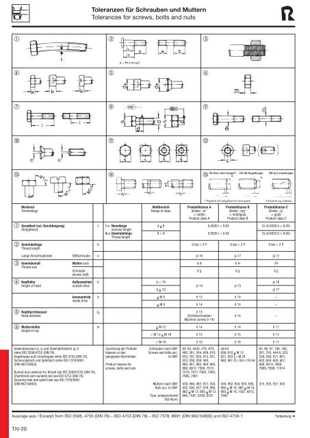
<strong>Toleranzen</strong> für <strong>Schrauben</strong> <strong>und</strong> <strong>Muttern</strong><br />
Tolerances for screws, bolts and nuts<br />
<br />
<br />
<br />
<br />
RL (Ko) ohne Kuppe1)<br />
<br />
CH (K) Kegelkuppe<br />
RN (L) Linsenkuppe<br />
1) Regelfall bei kaltgeformten <strong>Schrauben</strong> Einsenkung zulässig<br />
*<br />
Merkmal Maßbereich Produktklasse A Produktklasse B Produktklasse C<br />
Terminology Range of sizes (bisher „m“ (bisher „mg“ (bisher „g“<br />
= mittel) = mittelgrob = grob)<br />
Product class A Product class B Product class C<br />
Geradheit (zul. Durchbiegung) t l = Nennlänge d ≤ 8 0,0020 l + 0,05 2x (0,0020 b + 0,05)<br />
Straightness<br />
nominal length<br />
b = Gewindelänge d > 8 0,0025 l + 0,05 2x (0,0025 b + 0,05)<br />
Thread length<br />
Gewindelänge b 0 bis + 2 P 0 bis + 2 P 0 bis + 2 P<br />
Thread length<br />
Länge Einschraubende Stiftschraube e js 16 js 17 js 17<br />
Gewindemaß Mutter (nut) 6 H 6 H 7H<br />
Thread size<br />
Schraube 6 g 6 g 8 g<br />
(screw, bolt)<br />
Kopfhöhe Außenantrieb k k < 10 js 16<br />
Height of head outside drive js 14 js 15<br />
k ≥ 10 js 17<br />
Innenantrieb k ≤ M 5 h 13 h 14 –<br />
inside drive<br />
≤ M 5 h 14 h 14 –<br />
Kopfdurchmesser d k h 13<br />
Head diameter (Schlitzschrauben h 14 –<br />
Machine screws h 14)<br />
<strong>Muttern</strong>höhe m ≤ M 12 h 14 h 14 h 17<br />
Height of nut<br />
> M 12 ≤ M 18 h 15 h 15 h 17<br />
Gewindeauslauf (a, x) <strong>und</strong> Gewindefreistich (g, f)<br />
siehe ISO 3508/4755 (DIN 76).<br />
Kegelkuppe <strong>und</strong> Linsenkuppe siehe ISO 4753 (DIN 78).<br />
Sicherungsloch <strong>und</strong> Splintloch siehe ISO 7378/8991<br />
(DIN 962/34803).<br />
Runout and <strong>und</strong>ercut for thread see ISO 3508/4755 (DIN 76).<br />
Chamfered and ro<strong>und</strong>ed end see ISO 4753 (DIN 78).<br />
Securing hole and splint hole see ISO 7378/8991<br />
(DIN 962/34803).<br />
Zuordnung der Produktklassen<br />
zu den<br />
gängigsten Normteilen<br />
Product classes for<br />
screws, bolts and nuts<br />
> M 18 h 16 h 16 h 17<br />
<strong>Schrauben</strong> nach DIN*<br />
Screws and bolts acc.<br />
to DIN*<br />
<strong>Muttern</strong> nach DIN*<br />
Nuts acc. to DIN*<br />
*bzw. entsprechende<br />
ISO-Norm<br />
84, 85, 444C, 478, 479,<br />
480, 561, 564, 609, 610,<br />
653, 787, 835, 912, 931,<br />
933, 938, 939, 940,<br />
960, 961, 963, 964, 965,<br />
966, 6912, 7380, 7513,<br />
7516, 7971-7983, 7984,<br />
7985, 7991<br />
439, 466, 467, 917, 934,<br />
935, 936, 937, 979, 980,<br />
982 ≤ M 12, 985 ≤ M 12,<br />
986, 1587, 6330, 6331<br />
444 B<br />
609, 610 ≥ M 12<br />
931, 933 > M 24<br />
960, 961 } L>10d/>150 mm<br />
439, 562, 934, 935, 936,<br />
980 ≥ M 16, 982 ≥ M 16,<br />
985 ≥ M 16, 1587, 6915,<br />
7965<br />
95, 96, 97, 186, 188,<br />
261, 316, 444 A, 525,<br />
529, 558, 571, 601,<br />
603, 604, 605, 607,<br />
608, 6914, 7968,<br />
7969, 7990, 11014<br />
315, 555, 557, 935<br />
Auszüge aus / Excerpt from ISO 3508, 4755 (DIN 76) – ISO 4753 (DIN 78) – ISO 7378, 8991 (DIN 962/34803) <strong>und</strong> ISO 4759-1<br />
Fortsetzung ➔<br />
TiV-20
<strong>Toleranzen</strong> für <strong>Schrauben</strong> <strong>und</strong> <strong>Muttern</strong><br />
Tolerances for screws, bolts and nuts<br />
Merkmal Maßbereich Produktklasse A Produktklasse B Produktklasse C<br />
Terminology Range of sizes (bisher „m“ (bisher „mg“ (bisher „g“<br />
= mittel) = mittelgrob = grob)<br />
(Bezugsmaß für„t“) Product class A Product class B Product class C<br />
Nennlänge l l ≤ 150 js 15 js 17 js 17<br />
Nominal length<br />
(Schlitzschrauben<br />
l > 150 machine screws js 17 2 js 17<br />
l > 50 js 16)<br />
Oberflächen-Rauhheit Außenfläche Auflagefläche, Schaft R t = 25 µm R t = 25 µm beliebig<br />
Surface condition Outs. surf. Under head, shank unspecified<br />
Übrige Flächen R t = 25 µm beliebig beliebig<br />
Remaining surfaces unspecified unspecified<br />
Kuppe, Schlüsselfläche R t = 100 µm beliebig beliebig<br />
End, across flat unspecified unspecified<br />
Gewinde Flanke Schraube, Mutter R t = 25 µ (≤ M 5 = R t = 25 µm R t = 40 µm<br />
Thread Thread screw, bolt, nut 16 µm/geschnitten (geschnitten = 40 µm)<br />
> M 5 = 40 µm)<br />
Kern Schraube R t = 25 µm R t = 25 µm R t = 40 µm<br />
Base screw, bolt<br />
Kern Mutter beliebig beliebig beliebig<br />
Base nut unspecified unspecified unspecified<br />
Außen-Ø Schraube beliebig beliebig beliebig<br />
Outside-Ø screw, bolt unspecified unspecified unspecified<br />
R<strong>und</strong>lauf, Symmetrie Schraube s:d (s) 2 IT 13 2 IT 14 2 IT 15<br />
Concentricity, symmetry screw, bolt<br />
dk:d (dk) 2 IT 13 2 IT 14 2 IT 15<br />
n:d (d) 2 IT 12 2 IT 13 2 IT 14<br />
R<strong>und</strong>lauf, Symmetrie Mutter s:d (Kern) (s) 2 IT 13 2 IT 14 2 IT 15<br />
concentricity, symmetry nut<br />
n:d (Kern) (d) 2 IT 13 2 IT 14 2 IT 15<br />
Schaftdurchmesser d s h 13 h 14 ± IT 15<br />
Shank diameter<br />
Dünnschaft: Schaftdurchmesser ~ Flankendurchmesser<br />
Reduced shank: Shank diameter ~ mean diameter<br />
Schlitzbreite 1) n n ≤ 1 + 0,20 bis + 0,06<br />
width of slot<br />
n > 1 ≤ 3 + 0,31 bis + 0,06 – –<br />
n > 3 ≤ 6 + 0,37 bis + 0,07<br />
Schlüsselweite Außenantrieb s s ≤ 32 = h 13 s ≤ 19 = h 14 / s > 19 ≤ 60 = h 15<br />
Across flat dim. outside drive s > 32 = h 14 s > 60 ≤ 180 = h 16 / s > 180 = h 17<br />
Innenantrieb s s 0,7 = EF 8/ s 0,9 =<br />
inside drive JS 9/ s 1,3 = K 9<br />
s 1,5-2 = D 10 (D 9 2 )/<br />
s 2,5 = D 11 (D 10 2 ) – –<br />
s 3 = D 11/s 4 = E 11/<br />
s 5-14 = E 12 (E 11 2 )<br />
s > 14 = D 12<br />
Winkel 90° < M39 ± 1° ± 1° ± 2°<br />
Angle<br />
> M 39 ± 1/2° ± 1/2° ± 1°<br />
1) Tiefe für Schlitze <strong>und</strong> Innensechskante<br />
siehe Produkt-(Maß-) Normen.<br />
Depth for slots and hexagon sockets see standard sheets.<br />
2) Toleranzfelder für Gewindestifte mit Innensechskant<br />
Tolerance zones f. hex. socket set screws<br />
Gewindeauslauf (a, x) <strong>und</strong> Gewindefreistich (g, f) siehe ISO 3508/4755<br />
(DIN 76). Kegelkuppe <strong>und</strong> Linsenkuppe siehe ISO 4753 (DIN 78).<br />
Sicherungsloch <strong>und</strong> Splintloch siehe ISO 7378/8991 (DIN 962/34803).<br />
Runout and <strong>und</strong>ercut for thread see ISO 3508/4755 (DIN 76).<br />
Chamfered and ro<strong>und</strong>ed end see ISO 4753 (DIN 78).<br />
Securing hole and splint hole see ISO 7378/8991 (DIN 962/34803).<br />
<br />
Zuordnung der Produktklassen<br />
zu den<br />
gängigsten Normteilen<br />
Product classes for<br />
screws, bolts and nuts<br />
Außengewinde a 1 x 1 g 1 g 2 u z 1 z 2<br />
NennØ Steigung (f 1 ) (f 2 ) 2 p + IT 14 + IT 14<br />
M P max. max. min. max. max.<br />
3 0,5 1,5 1,25 1,1 1,75 1 0,75 1,5<br />
4 0,7 2,1 1,75 1,5 2,45 1,4 1 2<br />
5 0,8 2,4 2 1,7 2,8 1,6 1,25 2,5<br />
6 1 3 2,5 2,1 3,5 2 1,5 3<br />
8 1,25 3,75 3,2 2,7 4,4 2,5 2 4<br />
10 1,5 4,5 3,8 3,2 5,2 3 2,5 5<br />
12 1,75 5,25 4,3 3,9 6,1 3,5 3 6<br />
14 2 6 5 4,5 7 4 3,5 7<br />
16 2 6 5 4,5 7 4 4 8<br />
18 2,5 7,5 6,3 5,6 8,7 5 4,5 9<br />
= Auszug aus ISO 3508/4755 (DIN 76)<br />
a 1 = Abstand des letzten vollen Gewindegangs von der Anlagefläche (bei Teilen mit Gewinde bis Kopf)<br />
x 1 = Gewindeauslauf Regelfall<br />
g (f) = Gewindefreistich Regelfall (Form A)<br />
<br />
<strong>Schrauben</strong> nach DIN*<br />
Screws and bolts acc.<br />
to DIN*<br />
<strong>Muttern</strong> nach DIN*<br />
Nuts acc. to DIN*<br />
*bzw. entsprechende<br />
ISO-Norm<br />
84, 85, 444C, 478, 479,<br />
480, 561, 564, 609, 610,<br />
653, 787, 835, 912, 931,<br />
933, 938, 939, 940,<br />
960, 961, 963, 964, 965,<br />
966, 6912, 7380, 7513,<br />
7516, 7971-7983, 7984,<br />
7985, 7991<br />
439, 466, 467, 917, 934,<br />
935, 936, 937, 979, 980,<br />
982 ≤ M 12, 985 ≤ M 12,<br />
986, 1587, 6330, 6331<br />
<br />
444 B<br />
609, 610 ≥ M 12<br />
931, 933 > M 24<br />
960, 961 } L>10d/>150 mm<br />
439, 562, 934, 935, 936,<br />
980≥ M 16, 982≥ M 16,<br />
985≥ M 16, 1587, 6915,<br />
7965<br />
95, 96, 97, 186, 188,<br />
261, 316, 318, 444 A,<br />
525, 529, 558, 571,<br />
601, 603, 604, 605,<br />
607, 608, 6914, 7968,<br />
7969, 7990, 11014<br />
314, 315,<br />
555, 557, 935<br />
Außengewinde a 1 x 1 g 1 g 2 u z 1 z 2<br />
NennØ Steigung (f 1 ) (f 2 ) 2 p + IT 14 + IT 14<br />
M P max. max. min. max. max.<br />
20 2,5 7,5 6,3 5,6 8,7 5 5 10<br />
22 2,5 7,5 6,3 5,6 8,7 5 5,5 11<br />
24 3 9 7,5 6,7 10,5 6 6,7 12<br />
27 3 9 7,5 6,7 10,5 6 6,7 13,5<br />
30 3,5 10,5 9 7,7 12 7 7,5 15<br />
33 3,5 10,5 9 7,7 12 7 8,2 16,5<br />
36 4 12 10 9 14 8 9 18<br />
39 4 12 10 9 14 8 9,7 19,5<br />
42 4,5 13,5 11 10,5 16 9 10,5 21<br />
45 4,5 13,5 11 10,5 16 9 22,5<br />
= Auszug aus ISO 4753 (DIN 78)<br />
u = unvollständiges Gewinde an <strong>Schrauben</strong>enden (Regelfall für <strong>Schrauben</strong> m. gerolltem Gewinde)<br />
z 1 = Länge Kernansatz bei Ausfg. Ka<br />
z 2 = Länge Zapfen bei Ausfg. Za (Z)<br />
<br />
Auszüge aus / Excerpt from ISO 3508, 4755 (DIN 76) – ISO 4753 (DIN 78) – ISO 7378, 8991 (DIN 962/34803) <strong>und</strong> ISO 4759-1<br />
TiV-21