Datenblatt - Oswald Elektromotoren GmbH
Datenblatt - Oswald Elektromotoren GmbH
Datenblatt - Oswald Elektromotoren GmbH

Sie wollen auch ein ePaper? Erhöhen Sie die Reichweite Ihrer Titel.
YUMPU macht aus Druck-PDFs automatisch weboptimierte ePaper, die Google liebt.
Regelbare<br />
Drehstrom-Synchronmotoren<br />
Baureihe MF<br />
mit Wasserkühlung<br />
REGELBARE ELEKTROMOTOREN<br />
speed controlled<br />
PM synchronous motors<br />
Series MF<br />
water-cooled<br />
<strong>Elektromotoren</strong> <strong>GmbH</strong><br />
63897 Miltenberg - Benzstraße 12 - Telefon: ++49 9371 9719-0<br />
www.oswald.de - eMail: oswald@oswald.de - Telefax: ++49 9371 9719-50
Technical data series MF<br />
Technische Daten Baureihe MF<br />
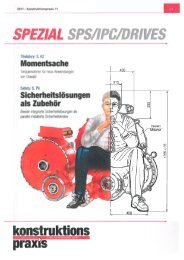
Power and torque characteristic<br />
Leistungs- und Drehmomentdiagramm<br />
Power - Torque Leistung - Drehmoment<br />
Base speed range<br />
Grunddrehzahlbereich<br />
Torque S3<br />
Moment S3<br />
Torque S1<br />
Moment S1<br />
Field weakening range<br />
Feldschwächbereich<br />
Power S3<br />
Leistung S3<br />
Power S1<br />
Leistung S1<br />
Faktor<br />
max.<br />
max.<br />
delta<br />
max.<br />
Hinweis: bei red. Eckleistung werden die<br />
n N<br />
n F n max<br />
Speed Drehzahl<br />
Bemessung 75Hz - 1500min -1 - 3 x 350V<br />
Rating 75Hz - 1500min -1 - 3 x 350V<br />
Other voltage and speed on request<br />
Higher maximum speed with adapted developments on request<br />
Technical Data MF25..31 on demand<br />
Version 0626<br />
Typ M N M max P N I N eta I max n max<br />
1)<br />
(Nm) (Nm) (kW) (A) (%) (A) (1/min) (kgm²) (kg)<br />
MF 09.1 - 6 64 100 10,1 22,5 88 37 9000 0,009 40<br />
MF 09.2 - 6 93 141 14,6 33 89 53 9000 0,011 45<br />
MF 09.3 - 6 124 181 19,5 44,5 89 65 9000 0,015 55<br />
MF 11.1 - 6 110 170 17,3 39 90 63 7500 0,022 70<br />
MF 11.2 - 6 153 228 24,0 54 91 85 7500 0,029 78<br />
MF 11.3 - 6 195 284 30,6 69 91 106 7500 0,036 85<br />
MF 13.2 - 6 258 441 40,6 87 93 156 6500 0,069 125<br />
MF 13.3 - 6 365 607 57,4 122 93 213 6500 0,096 145<br />
MF 16.2 - 6 450 760 70,7 143 95 253 5500 0,174 205<br />
MF 16.3 - 6 605 968 95,1 201 95 338 5500 0,219 230<br />
MF 18.2 - 6 820 1467 129,0 262 96 492 4500 0,351 310<br />
MF 18.3 - 6 1040 1795 163,7 336 96 609 4500 0,436 350<br />
MF 20.2 - 6 1150 1710 180,7 366 96 572 4500 0,574 425<br />
MF 20.3 - 6 1290 1905 202,7 416 97 645 4500 0,629 450<br />
MF 22.2 - 6 1400 2410 220,1 451 97 815 4000 1,000 570<br />
Bemessung 150Hz - 3000min -1 - 3 x 350V<br />
Typ M N M max P N I N eta I max n max<br />
1)<br />
J<br />
Gew.<br />
Rating 150Hz - 3000min -1 - 3 x 350V<br />
(Nm) (Nm) (kW) (A) (%) (A) (1/min) (kgm²) (kg)<br />
MF 09.1 - 6 54 100 17,0 35 92 68 9000 0,009 40<br />
MF 09.2 - 6 75 140 23,6 49 93 96 9000 0,011 45<br />
MF 09.3 - 6 96 180 30,2 62 93 122 9000 0,015 55<br />
MF 11.1 - 6 89 169 28,0 57 93 114 7500 0,022 70<br />
MF 11.2 - 6 119 226 37,4 79 94 157 7500 0,029 78<br />
MF 11.3 - 6 148 282 46,5 93 94 186 7500 0,036 85<br />
MF 13.2 - 6 171 439 53,9 102 95 275 6500 0,069 125<br />
MF 13.3 - 6 233 606 73,4 138 95 377 6500 0,096 145<br />
MF 16.2 - 6 291 759 91,9 168 95 460 5500 0,174 205<br />
MF 16.3 - 6 366 966 115,5 214 95 593 5500 0,219 230<br />
MF 18.2 - 6 500 1465 157,8 284 97 874 4500 0,351 310<br />
MF 18.3 - 6 600 1790 189,1 371 97 1163 4500 0,436 350<br />
MF 20.2 - 6 660 1705 208,2 384 97 1042 4500 0,574 425<br />
MF 20.3 - 6 740 1900 233,2 430 97 1160 4500 0,629 450<br />
MF 22.2 - 6 805 2405 254,3 495 97 1553 4000 1,000 570<br />
The details made in this leaflet are general descriptions and performance features.<br />
In particular cases those may differ from the leaflet data and may change due to further developments<br />
in our product range. The desired performance features are obligatory only if those are particularly<br />
agreed at completion of a contract.<br />
J<br />
Gew.<br />
Andere Spannung und Drehzahl auf Anfrage<br />
Maximale Feldschwächedrehzahl: 1,8xNnenn ( Umrichtereigenschaften vorausgesetzt).<br />
1) Mechanisch zulässige Höchstdrehzahl mit Standardlagerung. Höhere Drehzahlen auf Anfrage.<br />
Technische Daten MF25..31 auf Anfrage<br />
Die in diesem Prospekt gemachten Angaben sind allgemeine Beschreibungen und Leistungsmerkmale, die<br />
im konkreten Einzelfall nicht immer in der beschriebenen Form zutreffen bzw. sich durch Weiterentwicklung<br />
unserer Produkte ändern können.<br />
Die gewünschten Leistungsmerkmale sind nur dann verbindlich, wenn sie bei Vertragsabschluss<br />
ausdrücklich vereinbart werden.<br />
<strong>Elektromotoren</strong> <strong>GmbH</strong>
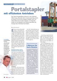
Mechanical dimensions MF<br />
Mechanische Abmessungen MF<br />
1a MF09 with radial water connection<br />
1b MF11 .. MF22 with axial water connection<br />
2 Position water connection depends on terminal box position<br />
3 flexible hoses for water connection, length 300 mm<br />
4 Standard Resolver or SinCos encoder<br />
1a MF09 mit radialem Wasseranschluß<br />
1b MF11 .. MF22 mit axialem Wasseranschluß<br />
2 Position Wasseranschluß abhängig von Klemmkastenlage<br />
3 flexible Panzerschläuche zum Wasseranschluß, Länge 300mm<br />
4 Standard Resolver oder SinCos-Geber<br />
Typ L X1 LT D1 AD KX KY s3 s4 W1 W2 R flow rate<br />
x 1.5<br />
Durchfluß<br />
MF09.1 337 185 120<br />
MF09.2 387 235 40 205 188 171 186 M32 M16 73 170 G1/2" 5 L/min<br />
MF09.3 437 285 220<br />
MF11.1 445 232<br />
MF11.2 495 282<br />
MF11.3 545 332<br />
MF13.2 561 316<br />
MF13.3 651 406<br />
MF13.4 691 446<br />
MF16.2 665 410 283 233 224 M50<br />
35 320<br />
MF16.3 755 516 297 303 303 2x M50<br />
MF18.2 870 541<br />
MF18.3 980 631<br />
40<br />
35<br />
40<br />
254 210<br />
295<br />
368<br />
171 186 M32<br />
265 233 224<br />
345 386<br />
3x M50<br />
MF20.2 885 578 385 386 365 3x M50<br />
40 418<br />
MF20.3 930 563 418 467 490 3x M72x2<br />
6 L/min<br />
7 L/min<br />
9 L/min<br />
11 L/min<br />
13 L/min<br />
MF22.2 965 599 40 452 425 467 490 3x M72x2 M16 35° 21° G3/4" 15 L/min<br />
M50<br />
M16<br />
M16<br />
41°<br />
M16 46°<br />
M16 34°<br />
Typ M N P z S T LA Q D DZ E GA F<br />
365<br />
M16<br />
41°<br />
33°<br />
26°<br />
26°<br />
23°<br />
33°<br />
23°<br />
G1/2"<br />
G1/2"<br />
G1/2"<br />
G1/2"<br />
G1/2"<br />
MF09.1<br />
MF09.2<br />
MF09.3<br />
MF11.1<br />
MF11.2<br />
MF11.3<br />
MF13.2<br />
MF13.3<br />
MF13.4<br />
MF16.2<br />
MF16.3<br />
MF18.2<br />
MF18.3<br />
MF20.2<br />
MF20.3<br />
MF22.2 400 350 450 8 18 5 25 434 75 M20 140 79,5 20<br />
Dimensions in mm<br />
Terminal box turnable about 90°, position on top / left / right possible<br />
Flange acc. to DIN42948, shaft end acc. to DIN748-3, fitting key acc. to DIN6885-1<br />
Special flange and adaptional dimensions on request<br />
Dimensions MF25..31 on demand<br />
The details made in this leaflet are general descriptions and performance features.<br />
In particular cases those may differ from the leaflet data and may change due to further developments<br />
in our product range. The desired performance features are obligatory only if those are particularly<br />
agreed at completion of a contract.<br />
Version 0626<br />
215<br />
300<br />
300<br />
350<br />
350<br />
400<br />
180 250<br />
250 350 4 18 5 15 246 42<br />
250 334<br />
4 18 5 15<br />
300 386 4 18 5 20 310 55<br />
300 400<br />
4 13 4 15<br />
4 18 5 20<br />
350 450 4 19 5 22 380 70<br />
194 28 M10 60<br />
260 48 M16 110<br />
320 60 M20 140<br />
30,9 8<br />
M16 110 41,3 10<br />
51,5 14<br />
M16 110 59 16<br />
64 18<br />
M20 140 74,5 20<br />
Maße in mm<br />
Klemmenkasten um je 90° drehbar, Position oben / links / rechts möglich<br />
Flansch nach DIN42948, Wellenende nach DIN748-3, Paßfeder nach DIN6885-1<br />
Flansch- und Anschlußmaße in Sonderausführung auf Anfrage<br />
Abmessungen MF25..31 auf Anfrage<br />
Die in diesem Prospekt gemachten Angaben sind allgemeine Beschreibungen und Leistungsmerkmale, die<br />
im konkreten Einzelfall nicht immer in der beschriebenen Form zutreffen bzw. sich durch Weiterentwicklung<br />
unserer Produkte ändern können.<br />
Die gewünschten Leistungsmerkmale sind nur dann verbindlich, wenn sie bei Vertragsabschluss<br />
ausdrücklich vereinbart werden.<br />
<strong>Elektromotoren</strong> <strong>GmbH</strong>
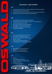
Type designation (example)<br />
Typenbezeichnung (Beispiel)<br />
Series ............. MF<br />
Baureihe .......... MF<br />
Size acc. IEC<br />
Baugröße nach IEC<br />
Length<br />
Baulänge<br />
MF 13 . 3 -6 W B R<br />
R: Motor with resolver<br />
R: Motor mit Resolver<br />
S: Motor with SinCos encoder<br />
S: Motor mit SinCos-Geber<br />
B: Motor with brake<br />
B: Motor mit Bremse<br />
water cooled<br />
wassergekühlt<br />
pole 6<br />
6-polig<br />
Typical applications<br />
The synchronous motors of the MF-series are best suited<br />
for extruding and injection moulding machines, machine<br />
tools, vehicle drives, testing systems, packaging machines,<br />
extruder, textile machines, wire drawing mills, printing<br />
machines, hydro-electric power plants, etc...<br />
OSWALD products<br />
Three-phase asynchronous motors and generators<br />
Series FQD - water cooled<br />
Series QD - surface cooled / seperately ventilated<br />
Series QDi - internally cooled / seperately ventilated<br />
Synchronous motors and generators<br />
Series MF - water cooled<br />
Series MA - surface cooled / seperately ventilated<br />
Series MI - internally cooled / seperately ventilated<br />
Synchronous torque motors and generators<br />
Series TF - water cooled<br />
Series TU - without cooling<br />
Synchronous linear motors<br />
Series LINS - in cylindrical construction<br />
Series LIFS - in flat construction<br />
water cooled or forced ventilated<br />
High Tech Research<br />
Magnetic field technology<br />
Superconducting motors<br />
Typische Anwendungen<br />
Die Synchronmotoren der Baureihe MF eignen sich<br />
besonders für Spritzgießmaschinen, Werkzeugmaschinen,<br />
Fahrzeugantriebe, Prüfstandstechnik,<br />
Verpackungsmaschinen, Extruder, Textilmaschinen,<br />
Drahtziehmaschinen, Druckmaschinen,<br />
Blockheizkraftwerke, Wasserkraftgeneratoren, etc...<br />
OSWALD Lieferprogramm<br />
Drehstrom-Asynchronmotoren und -Generatoren<br />
Baureihe FQD - flüssigkeitsgekühlt<br />
Baureihe QD - oberflächen-/fremdbelüftet<br />
Baureihe QDi - innen-/fremdbelüftet<br />
Synchron-Motoren und -Generatoren<br />
Baureihe MF - flüssigkeitsgekühlt<br />
Baureihe MA - oberflächen-/fremdbelüftet<br />
Baureihe MI - innen-/fremdbelüftet<br />
Synchron-Torque-Motoren und -Generatoren<br />
Baureihe TF - flüssigkeitsgekühlt<br />
Baureihe TU - unbelüftet<br />
Synchron-Linear-Motoren<br />
Series LINS - in zylindrischer Ausführung<br />
Series LIFS - in flacher Ausführung<br />
flüssigkeitsgekühlt oder fremdbelüftet<br />
High Tech Forschung<br />
Magnetfeldtechnik<br />
Supraleitende Motoren<br />
The details made in this leaflet are general descriptions and performance features. In particular cases those may differ from the leaflet data and may change due to<br />
further developments in our product range. The desired performance features are obligatory only if those are particularly agreed at completion of a contract.<br />
Die in diesem Prospekt gemachten Angaben sind allgemeine Beschreibungen und Leistungsmerkmale, die im konkreten Einzelfall nicht immer in der beschriebenen<br />
Form zutreffen bzw. sich durch Weiterentwicklung unserer Produkte ändern können.<br />
Die gewünschten Leistungsmerkmale sind nur dann verbindlich, wenn sie bei Vertragsabschluss ausdrücklich vereinbart werden.<br />
<strong>Elektromotoren</strong> <strong>GmbH</strong>
General description<br />
Liquid-cooled OSWALD synchronous motors and<br />
generators series MF<br />
are particularly suitable when heavy<br />
demands are placed on a drive system. The motors are<br />
designed for wide speed range and high dynamic operation.<br />
OSWALD 6-pole MF motors in power ranges from<br />
1kW to 175kW are characterized by highest power density<br />
with small space requirements.<br />
The totally enclosed MF motors are cooled over the<br />
integrated cooling jacket by water or oil.<br />
A high degree of reliability and low maintainance<br />
requirements result from use of prelubricated bearings as<br />
well as stable housing and bearing plates.<br />
MF motors are designed for controlled drives with frequency<br />
inverters. Mounting of resolver or SinCos encoder is<br />
standard, other encoders on demand.<br />
The MF<br />
series is the result of many years of experience with<br />
frequency controlled 3-phase squirrel cage motors. During<br />
development special attention was paid to low noise, high<br />
acceleration and break down torque, low rotor inertia and<br />
high maximum speed with a minimum of vibration.<br />
Design<br />
The motors are designed acc. to relevant standards and<br />
regulations, particularly DIN EN 60034/VDE 0530-1,<br />
DIN42676/42677/42948. An exception to this is the<br />
arrangement of shaft dimensions and partially the flange<br />
dimensions; on this please see detailled dimension sheets.<br />
Mechanical mountings: B5, V1, B3, B35.<br />
Power<br />
The power ratings in the tables are valid for rating 100Hz<br />
and 150Hz.<br />
The motors can be controlled up to the specified nominal<br />
speed nN<br />
at constant torque and up to speed nF<br />
at constant<br />
power. At speed higher than n the power is reduced.<br />
Rating power PN<br />
for continuous operation S1 with corresponding<br />
data frequency, torque and current are specified.<br />
S3-power: P S3-x%ED = P / sqrt ( x% /100%).<br />
If desired other voltage, nominal speed and speed range<br />
can be offered.<br />
For inverter size please see nominal and overload current.<br />
Cooling system<br />
The losses of liquid-cooled motors are carried off by means<br />
of the cooling medium (mostly water). In the series MF the<br />
liquid flows through an integrated cooling jacket.<br />
The cooling system of OSWALD MF motors is resistant to<br />
aggressive mediums due to the use of stainless steel or<br />
copper, therefore the water needs no corrosion preventive.<br />
In open cooling systems clear cooling water must be used.<br />
The pollution by dirt particles should be avoid by installing<br />
filter systems (filtering
Insulatation class, enclosure<br />
- Insulation class F acc. to DIN EN 60034 / VDE 0530<br />
(Winding temperature rise 105 K)<br />
- Winding insulation is designed for inverter operation,<br />
maximum voltage slopes of 5kV/µs at the motor terminals<br />
- Temperature monitoring: 3PTC+2KTY-sensors (standard),<br />
other sensors optional<br />
- Enclosure IP54 .. IP65 acc. to DIN EN60034/VDE 0530<br />
- The position and orientation of the terminal box and the<br />
types of cables may be specified by the customer<br />
Vibration levels, balancing<br />
The MF motors are supplied at least in vibration level R<br />
(reduced) acc. to DIN/EN standards. Vibrational severity<br />
class S or extended ranges can also be realised to the<br />
customers demands.<br />
Balancing is performed with half-key.<br />
Noise level<br />
The MF motors feature lowest noise level .<br />
On demand measuring reports can be supplied.<br />
Bearings<br />
The motors in the MF series are equipped with deep groove<br />
ball bearings. The bearings are designed for a lifetime of at<br />
least 20.000 h, admissible load values can be specified on<br />
request. Cylindrical roller bearings or double bearings<br />
should be installed at high radial loads. Precision spindle<br />
bearings can be used to obtain higher vibration quality or an<br />
extended speed range.<br />
Attachments, encoder, brake<br />
On demand numerous attachments can be offered.<br />
The required encoder for speed or position are selected for<br />
drive requirements.<br />
Standard encoder can be determined from OSWALD,<br />
standard encoder connection with 12-poles connector.<br />
Mounting of brakes on non driven end on demand.<br />
Terminal box<br />
The position of the terminal box is usually on top, non driven<br />
end, cable connection with metric screw thread to the right<br />
side (view from driven end). Adapting on customers<br />
demands ist widely possible.<br />
Quality assurance - service<br />
An extensive quality control and assurance program has<br />
been the basis for the most stringent demands and had<br />
been reworked according to the guidelines in DIN EN ISO<br />
9001. The certification was gained first time in 1996.<br />
Qualified service personal are available for fitting,<br />
commissioning and maintenance work. They can also be on<br />
site on short notice in case of servicing emergencies.<br />
Spare parts can generally be shipped the same day they are<br />
ordered to provide direct assistance in case of machine<br />
malfunction.<br />
Wärmeklasse, Schutzart<br />
- Wärmeklasse F entsprechend DIN EN 60034 / VDE 0530<br />
(Wicklungsübertemperatur 105 K)<br />
- Wicklungsisolation für Umrichterbetrieb geeignet,<br />
Spannungsflanken max. zul. 5kV/µs an den Klemmen<br />
- Temperaturüberwachung: 3PTC+2KTY (Standard),<br />
andere Sensoren optional<br />
- Schutzart IP54 bis IP65 nach DIN EN60034/VDE 0530<br />
- Klemmkastenlage und -orientierung sowie<br />
Kabelausführungen variabel, gemäß Kundenwunsch<br />
Schwinggüte, Wuchtgüte<br />
Die MF-Motoren werden gemäß DIN/EN-Vorschriften<br />
mindestens in der Schwingstärkestufe R (reduziert) geliefert.<br />
Die Schwingstärke S oder weiter reduzierte Schwingstärken<br />
können auf Kundenwunsch realisiert werden.<br />
Die Wuchtung erfolgt mit halber Paßfeder.<br />
Geräuschstärke<br />
Die MF-Motoren zeichnen sich durch sehr niedrige<br />
Geräusche aus. Auf Anfrage können Meßprotokolle<br />
geliefert werden.<br />
Lagerung<br />
Die Motoren der MF-Reihe sind mit Rillenkugellagern<br />
ausgerüstet. Die Lager sind für eine Lebensdauer von<br />
mindestens 20.000 h dimensioniert, zulässige Belastungswerte<br />
können auf Anfrage angegeben werden. Bei hoher<br />
Radialbelastung werden Zylinderrollenlager oder<br />
Doppellager verwendet. Um höhere Schwinggüten oder<br />
einen erweiterten Drehzahlbereich zu erhalten, können<br />
Genauigkeits-Schrägkugellager bzw. Spindellager<br />
eingesetzt werden.<br />
Anbauten, Geber, Bremse<br />
Auf Kundenwunsch können zahlreiche Anbauten angeboten<br />
werden. Die erforderlichen Drehzahl- oder Lagegeber<br />
werden gemäß der Antriebsaufgabe ausgewählt.<br />
Standardgeber können von uns vorgegeben werden, der Anschluß<br />
erfolgt standardmäßig über einen 12-poligen Stecker.<br />
B-seitiger Bremsanbau auf Kundenwunsch möglich.<br />
Klemmkasten<br />
Der Klemmkasten befindet sich standardmäßig an der B-<br />
Seite oben, Kabelausführung mit metrischen Gewinden<br />
nach rechts (bei Sicht auf AS). Eine Anpassung an<br />
Kundenwünsche ist weitgehend möglich.<br />
Qualitätssicherung - Service<br />
Ein effektives Qualitätskontroll- und -sicherungssystem ist<br />
bei OSWALD seit Jahren die Basis für höchste<br />
Qualitätsansprüche und wurde 1996 erstmals nach den<br />
Richtlinien der DIN EN ISO 9001 geprüft und zertifiziert.<br />
Für Montagen, Inbetriebnahmen und Wartungsarbeiten<br />
steht qualifiziertes Personal für Servicefälle kurzfristig zur<br />
Verfügung.<br />
Ersatzteilbestellungen können in der Regel noch am<br />
gleichen Tage ausgeliefert werden, so daß auch bei einem<br />
Maschinenstillstand unmittelbar geholfen werden kann.<br />
Subject to change without notice<br />
Änderungen vorbehalten<br />
Version 0626<br />
<strong>Elektromotoren</strong> <strong>GmbH</strong>