UZK24 Series UZO24 Series - PULS GmbH
UZK24 Series UZO24 Series - PULS GmbH
UZK24 Series UZO24 Series - PULS GmbH
Sie wollen auch ein ePaper? Erhöhen Sie die Reichweite Ihrer Titel.
YUMPU macht aus Druck-PDFs automatisch weboptimierte ePaper, die Google liebt.
1 EN <strong>UZK24</strong> Instruction Manual 24V Battery module<br />
2 DE <strong>UZK24</strong> Bedienungsanleitung 24V Batteriemodul<br />
3 FR <strong>UZK24</strong> Manual d'instructions 24V Pack batterie<br />
4 ES <strong>UZK24</strong> Manual de instrucciones 24V Módulo de batería<br />
5 IT <strong>UZK24</strong> Manuale di Istruzione 24V Kit batteria<br />
6 PT <strong>UZK24</strong> Manual de Instruções 24V Módulo de bateria<br />
<strong>UZK24</strong> <strong>Series</strong><br />
<strong>UZO24</strong> <strong>Series</strong><br />
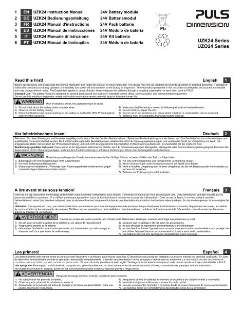
Read this first! English 1<br />
Before operating this unit please read this manual thoroughly and retain this manual for future reference! This device may only be installed and put into operation by qualified personnel. If damage or<br />
malfunction should occur during operation, immediately turn power off and send unit to the factory for inspection. The information presented in this document is believed to be accurate and reliable<br />
and may change without notice. The English text applies in cases of doubt. Always dispose the batteries through a recycling organization or send them back to <strong>PULS</strong>.<br />
Intended Use: This battery module is designed for general professional use such as in industrial control, office, communication, and instrumentation equipment.<br />
Do not use this module in equipment, where malfunction may cause severe personal injury or threaten human life.<br />
WARNING<br />
Risk of electrical shock, fire, personal injury or death.<br />
1) Do not short-circuit the battery poles or power wires<br />
2) Observe correct battery polarity<br />
3) Disconnect battery fuse before working on the battery or on the DC-UPS. Protect against<br />
inadvertent re-powering.<br />
4) Make sure that the wiring is correct by following all local and national codes.<br />
5) Do not modify or repair the unit.<br />
6) Do not use in wet locations or in areas where moisture or condensation can be expected.<br />
7) Batteries must be completely discharged before disposal.<br />
Vor Inbetriebnahme lesen! Deutsch 2<br />
Bitte lesen Sie diese Warnungen und Hinweise sorgfältig durch, bevor Sie das Gerät in Betrieb nehmen. Bewahren Sie die Anleitung zum Nachlesen auf. Das Gerät darf nur durch fachkundiges und<br />
qualifiziertes Personal installiert werden. Bei Funktionsstörungen oder Beschädigungen schalten Sie sofort die Versorgungsspannung ab und senden das Gerät zur Überprüfung ins Werk. Die<br />
angegebenen Daten dienen allein der Produktbeschreibung und sind nicht als zugesicherte Eigenschaften im Rechtssinne aufzufassen. Im Zweifelsfall gilt der englische Text.<br />
Bestimmungsgemäßer Gebrauch: Diese Modul ist für allgemeine elektronische Geräte, wie z.B. Industriesteuerungen, Bürogeräte, Messgeräte oder Kommunikationsgeräte geeignet. Benutzen Sie<br />
dieses Modul nicht in Steuerungsanlagen, in denen eine Funktionsstörung zu schweren Verletzungen führen oder Lebensgefahr bedeuten kann.<br />
WARNUNG<br />
Missachtung nachfolgender Punkte kann einen elektrischen Schlag, Brände, schwere Unfälle oder Tod zur Folge haben.<br />
1) Batteriepole und Anschlussleitungen nicht kurzschließen<br />
2) Korrekte Batteriepolarität beachten<br />
3) Sicherung vor Installations-, Wartungs- oder Änderungsarbeiten entfernen und gegen<br />
unbeabsichtigtes Wiedereinschalten sichern.<br />
4) Für eine ordnungsgemäße und fachgerechte Verdrahtung sorgen.<br />
5) Keine Veränderungen oder Reparaturversuche am Gerät durchführen.<br />
6) Nicht in feuchter Umgebung oder in einer Umgebung, bei der mit Betauung oder Kondensation zu<br />
rechnen ist, betreiben.<br />
7) Batterien vor Entsorgung komplett entladen<br />
A lire avant mise sous tension! Français 3<br />
Merci de lire ces instructions de montage et d'entretien avant de mettre l'alimentation sous tension. Conservez ce manuel qui vous sera toujours utile. Cette alimentation doit être installée par du<br />
personnel qualifié et compétent. Si un défaut quelconque apparaît en cours de fonctionnement, débrancher au plus vite l'alimentation. Dans ce cas de figure, il convient de faire contrôler<br />
l'alimentation en usine! Les données indiquées dans ce document servent uniquement à donner une description du produit et n'ont aucune valeur juridique. En cas de divergences, le texte anglais fait<br />
foi.<br />
Utilisation: Cet appareil est conçu pour être installé dans une armoire et pour tous les équipements électroniques, tel que l'équipement industriel de commande, l'équipement de bureau, le matériel<br />
de communication et les instruments de mesures. N'utilisez pas cet appareil pour des installations dans lesquelles un problème de fonctionnement de l'alimentation pourrait causer des blessures<br />
graves ou menacer la vie humaine.<br />
AVERTISSEMENT<br />
Prendre en compte les points suivants, afin d'éviter toute détérioration électrique, incendie, dommage aux personnes ou mort.<br />
1) Ne pas court-circuiter les pôles de la batterie ou les câbles de raccordement<br />
2) Respecter la polarité de la batterie<br />
3) débrancher l'installation avant toute intervention sur l'alimentation (ou démontage) et<br />
s'assurer qu'il n'y a pas risque de redémarrage.<br />
4) s'assurer que le câblage a été fait selon les prescriptions<br />
5) ne pas effectuer de réparations ou modifications sur l'alimentation<br />
6) ne pas faire fonctionner l'appareil dans un environnement humide ou à l'extérieur, non protégé. Ne<br />
pas utiliser l'appareil dans un environnement où il peut y avoir de la condensation.<br />
7) Les batteries doivent être déchargées complètement avant recyclage.<br />
Lea primero! Español 4<br />
Lea detenidamente este manual antes de conectar este dispositivo y consérvelo para futuras consultas. El dispositivo sólo puede ser instalado y puesto en marcha por personal cualificado. En caso<br />
de fallo o mal funcionamiento durante la operación, desconecte inmediatamente la tensión de alimentación y envíe el equipo a fábrica para su inspección. La información de este documento se<br />
considera precisa y fiable, y puede cambiar sin previo aviso. En caso de duda, prevalece el texto inglés. Deshágase de las baterias siempre a través de una red de reciclaje o devuélvalas a <strong>PULS</strong>.<br />
Uso apropiado: Este equipo ha sido diseñado para para uso general profesional, tal como instalaciones de control industrial, oficinas, comunicaciones y equipos de instrumentación.<br />
No emplee esta unidad en equipos, donde un mal funcionamiento puede ocasionar lesiones graves o riesgo mortal.<br />
ADVERTENCIA<br />
Riesgo de descarga eléctrica, incendio, accidente grave o muerte.<br />
1) No cortocircuitar los polos de la batería.<br />
2) Observe que la polaridad de la batería es correcta.<br />
3) Desconectar la tensión de red antes de trabajar en la fuente de alimentación. Evite una<br />
posible reconexión involuntaria.<br />
4) Asegurarse de que el cableado es correcto de acuerdo a los códigos locales y nacionales.<br />
5) No realizar ninguna modificación o reparación de la unidad.<br />
6) No usar en ambientes húmedos o en zonas donde se espere formación de rocío o condensación.<br />
7) Las baterías deben ser completamente descargadas antes de su eliminación.
Leggere prima questa parte! Italiano 5<br />
Prima di collegare il sistema di alimentazione elettrica si prega di leggere attentamente le seguenti avvertenze. Conservare le istruzioni per la consultazione futura. Il sistema di alimentazione elettrica<br />
deve essere installato solo da personale competente e qualificato. In caso di intervento del fusibile interno, molto probabilmente l'apparecchio è guasto. Se durante il funzionamento si verificano<br />
anomalie o guasti, scollegare immediatamente la tensione di alimentazione. In entrambi i casi è necessario far controllare l'apparecchio dal produttore! I dati sono indicati solo a scopo descrittivo del<br />
prodotto e non vanno considerati come caratteristiche garantite dell'apparecchio.In caso di differenze o problemi è valido il testo inglese<br />
Uso previsto: Questo apparecchio è previsto per il montaggio in un rack per moduli elettronici, ad esempio per controllori industriali, apparecchiature per ufficio, unità di comunicazione o apparecchi di<br />
misura. Non utilizzare questo apparecchio in apparati o impianti dove il malfunzionamento può causare danni alla persona o pericolo di vita.<br />
AVVERTENZA<br />
Il mancato rispetto delle seguenti norme può provocare folgorazione elettrica, incendi, gravi incidenti e perfino la morte.<br />
1) Non mettere in corto-circuito i poli della batteria o i cavi d’alimentazione<br />
2) Osservare la corretta polarità della batteria<br />
3) Prima di eseguire interventi di installazione, di manutenzione o di modifica, scollegare la<br />
tensione di rete ed adottare tutti i provvedimenti necessari per impedirne il ricollegamento<br />
non intenzionale.<br />
4) Assicurare un cablaggio regolare e corretto.<br />
5) Non tentare di modificare o di riparare da soli l'apparecchio.<br />
6) Non far funzionare l'apparecchio in un ambiente umido. Non far funzionare l'apparecchio in un<br />
ambiente soggetto alla formazione di condensa o di rugiada.<br />
7) Le batterie devono essere completamente scaricate prima dell’alienazione.<br />
Leia primeiro! Português 6<br />
Recomendamos a leitura cuidadosa deste manual antes de colocar do dispositivo e guarde as instruções para futura consulta. O dispositivo deverá ser instalado apenas por profissionais<br />
qualificados.Em caso de de defeito de funcionamento ou dano durante a utilização, desligue imediatamente a tensão da alimentação e envie o dispositivo à fábrica para inspecção. As informações<br />
contidas neste documento são consideradas precisas e confiáveise e podem mudar sem aviso prévio. Em caso de dúvidas aplica-se o texto em inglês. Sempre descarte de baterias através de uma<br />
empresa de reciclagem ou devolve-as para <strong>PULS</strong>.<br />
Aplicação: Este módulo de bateria foi concebido para o uso em dispositivos eletrónicos comuns, tais como instalações de controle industriais, equipamentos para escritórios e de comunicação,<br />
instrumentos de medição ou quadros eléctricos. Não utilize este móduolo em instalações, nos quais um defeito de funcionamento poderá causar danos graves ou significar risco de morte.<br />
ATENÇÃO<br />
A não observância ou o incumprimento dos pontos abaixo indicados poderá causar uma descarga elétrica, incêndios, acidentes graves ou morte.<br />
1) Não provoque curto-circuito nos pólos da bateria.<br />
2) Observe que a polaridade da bateria está correcta.<br />
3) Antes de trabalhos de instalação, manutenção ou modificação, desligue a tensão de<br />
alimentação, protegendo-a contra uma nova ligação involuntária.<br />
4) Assegure de que as cablagems sejam efectuadas em devida forma e de maneira competente,<br />
observando os códigos locais e nacionais.<br />
5) Não efectue nenhuma modificação ou tentativa de reparação no aparelho.<br />
6) Não usar o aparelho em ambientes húmidos ou em ambientes propensos a condensações.<br />
7) As baterias devem ser completamente descarregadas antes da eliminação.<br />
Product Description<br />
The <strong>UZK24</strong> battery modules utilize two non-spillable maintenance-free lead-acid batteries<br />
(connected in series), that are assembled in one package with all the required wiring included.<br />
Passive battery modules <strong>UZK24</strong>.071 and <strong>UZK24</strong>.121:<br />
The passive battery modules include the monitoring and protection board (sensor board) UZS01.<br />
This board contains a temperature sensor and a center-tap connection with an auto-resettable<br />
fuse to protect the center-tap wire between the battery module and the DC-UPS control unit.<br />
Connecting the center-tap wire to the DC-UPS control unit enables all the benefits of the <strong>PULS</strong> 1-<br />
Battery-Concept. This makes the use of matched replacement batteries unnecessary and allows a<br />
precise battery charging and testing which results in the longest possible battery life. Using the<br />
center tap connection is optional. Without this connection, the DC-UPS will function like a<br />
traditional UPS system without the above mentioned benefits.<br />
Intelligent battery modules <strong>UZK24</strong>.072 and <strong>UZK24</strong>.122:<br />
The intelligent battery modules are built-in in a IP20 enclosure and support a digital data transfer<br />
between the battery module and the DC-UPS (e.g. UB20) control unit. Battery voltage, battery<br />
temperature and battery resistance are reported very precisely to the control unit. Furthermore,<br />
these modules include a very sophisticated battery diagnosis with indicators on the control unit<br />
and the battery module itself. The battery-refresh function restores deep-discharged batteries,<br />
which cannot be charged with the standard charging method any more. Deep-discharge can occur<br />
when there is a long time interval (>12 month) during which the battery is not charged.<br />
All battery modules are available in two different options. They can be ordered with assembled<br />
batteries (UZK) or as a battery bracket without batteries (UZO), allowing for different battery<br />
options. The mounting bracket option also allows the batteries to be assembled just in time,<br />
avoiding outdated batteries due to limited shelf life.<br />
Produktbeschreibung<br />
Die <strong>UZK24</strong> Batteriemodule bestehen aus zwei in Serie geschalteten wartungsfreien VRLA<br />
Bleibatterien, welche in einem wand-montierbarem Metallrahmen mit den erforderlichen<br />
Verkabelungen, Anschlüssen und Schutzmaßnahmen versehen sind.<br />
Passive Batteriemodule <strong>UZK24</strong>.071 und <strong>UZK24</strong>.121:<br />
Die passiven Batteriemodule sind mit dem Überwachungs- und Schutzmodul (Sensorplatine)<br />
UZS01 ausgestattet. Dieses Modul enthält einen Temperatursensor und eine<br />
Anschlussmöglichkeit des Mittelpunkts (center-tap) der beiden Batterien. Der<br />
Mittelpunktanschluss ist im UZS01 durch eine selbstrücksetzende Sicherung strombegrenzt. Die<br />
Verwendung des Mittelpunktanschlusses ist optional und ermöglicht die individuelle Ladung und<br />
Überwachung der einzelnen Batterien. Alle Vorteile des <strong>PULS</strong> 1-Batterie Konzepts können<br />
ausgenutzt werden, und die Notwendigkeit von gepaarten Ersatzbatterien ist dadurch nicht<br />
erforderlich.<br />
Intelligente Batteriemodule <strong>UZK24</strong>.072 und <strong>UZK24</strong>.122:<br />
Die intelligenten Batteriemodule verwenden ein IP20 Gehäuse. Über eine digitale Schnittstelle<br />
werden Batterietemperatur, -spannung und –widerstand an die DC-USV (z.B. UB20) übertragen.<br />
Zusätzlich verfügen dies Module über eine umfangreiche Batteriediagnose, die sowohl an der DC-<br />
USV, als auch am Batteriemodul selbst angezeigt wird. Zu lange gelagerte Batterien (z.B. länger<br />
als 12 Monate), welche sich mit Standardladeverfahren nicht mehr laden lassen, können mit der<br />
integrierten Wiederbelebungsfunktion behandelt werden. Diese versucht mit einem optimierten<br />
Ladeverfahren die Sulfatierung der Batterie aufzulösen, um eine Ladung mit dem sicheren<br />
Standardladeverfahren wieder möglich zu machen.<br />
Alle Batteriemodule sind sowohl mit Batteriebestückung (UZK) als auch ohne Batteriebestückung<br />
(UZO) verfügbar. Dies erlaubt die Verwendung verschiedener eigener Batterietypen (z.B. mit<br />
optimierter Lebensdauer oder weiterem Temperaturbereich) und vermeidet wegen einer<br />
möglichen zu langen Lagerung vorgealtete Batterien, da diese erst kurz vor Verwendung<br />
eingesetzt werden können.<br />
Fig. 1a / Bild 1a <strong>UZK24</strong>.071, <strong>UZK24</strong>.121<br />
Wiring scheme passive battery modules/<br />
Verdrahtungsschema passive Batteriemodule<br />
Fig. 1b / Bild 1b <strong>UZK24</strong>.072, <strong>UZK24</strong>.122:<br />
Wiring scheme intelligent battery modules/<br />
Verdrahtungsschema intelligente Batteriemodule<br />
+ -<br />
DC-UPS<br />
Load<br />
Load<br />
X1<br />
Input<br />
Data/<br />
Temp.<br />
(11)<br />
RTN<br />
(12)<br />
DC-UPS<br />
Center<br />
Tap<br />
(13)<br />
Output<br />
X2<br />
Battery<br />
(+) (-)<br />
<strong>UZK24</strong>.071/ 121<br />
Battery Module<br />
Battery<br />
wires<br />
(+) (-)<br />
X1<br />
Temp. RTN<br />
(11) (12)<br />
Center<br />
Tap<br />
(13)<br />
+ -<br />
Battery<br />
X1<br />
Data/<br />
Temp.<br />
(11)<br />
Input<br />
RTN<br />
(12)<br />
Center<br />
Tap<br />
(13)<br />
Output<br />
X2<br />
(+)<br />
X2<br />
(-) (+)<br />
<strong>UZK24</strong>.072/ 122<br />
Battery Module<br />
(-)<br />
X1<br />
Data RTN<br />
(11) (12)<br />
Center<br />
Tap<br />
(13)<br />
optional<br />
Germany <strong>PULS</strong> in Munich +49 89 9278 0 www.pulspower.de<br />
China <strong>PULS</strong> in Suzhou +86 512 62881820 www.pulspower.cn<br />
France <strong>PULS</strong> in Limonest / Lyon +33 478 668 941 www.pulspower.fr<br />
North America <strong>PULS</strong> in St. Charles / Chicago +1 630 587 9780 www.pulspower.us<br />
Austria <strong>PULS</strong> in Rohrbach +43 27 64 32 13 www.pulspower.at<br />
Switzerland <strong>PULS</strong> in Oberflachs / Aargau +41 56 450 18 10 www.pulspower.ch<br />
United Kingdom <strong>PULS</strong> in Bedfordshire +44 845 130 1080 www.pulspower.co.uk<br />
Headquarters:<br />
<strong>PULS</strong> <strong>GmbH</strong><br />
Arabellastrasse 15<br />
D-81925 Munich<br />
Germany<br />
www.pulspower.com
<strong>UZK24</strong>: Battery Module Instruction Manual<br />
<strong>UZK24</strong>: Bedienungsanleitung für Batteriemodule<br />
Technical Data 1) Technische Daten 1) <strong>UZK24</strong>.071<br />
<strong>UZO24</strong>.071 2)<br />
<strong>UZK24</strong>.121<br />
<strong>UZO24</strong>.121 2)<br />
Module Type Modultyp Passive Module Passive Module<br />
Battery Type Batterietyp nom. VRLA (lead acid) VRLA (lead acid)<br />
Battery Design Life Ausgelegte Batterielebensdauer acc EUROBAT 3 to 5 years 3 to 5 years<br />
Voltage of Battery Module Spannung des Batteriemoduls nom. DC 24V<br />
(2x 12V in <strong>Series</strong>)<br />
DC 24V<br />
(2x 12V in <strong>Series</strong>)<br />
Battery Capacity Batteriekapazität nom. 7Ah 12Ah<br />
Battery Current<br />
for discharging<br />
for charging<br />
Batteriestrom<br />
bei Entladung<br />
bei Ladung<br />
Battery Fuse Batteriesicherung ATO Fuse 30A 30A<br />
Temperature Sensor Temperaturfühler - 1x for Module<br />
Temperature (PT1000)<br />
max.<br />
max.<br />
30A<br />
1.8A<br />
30A<br />
3.5A<br />
1x for Module<br />
Temperature (PT1000)<br />
Refresh Battery Function Batterie Wiederbelebungsfunktion No / Nein No / Nein<br />
Charging Voltage Ladespannung typ. 27.8V at 10°C<br />
27.5V at 20°C<br />
27.15V at 30°C<br />
26.8V at 40°C<br />
27.8V at 10°C<br />
27.5V at 20°C<br />
27.15V at 30°C<br />
26.8V at 40°C<br />
Self-discharge rate Selbstentladungsrate typ. at 20°C 3% / month 3% / month<br />
Isolation Voltage between Power or<br />
Signal Circuits to Chassis<br />
Temperature Range<br />
for discharging<br />
for charging<br />
Isolationsspannung zw. Leistungsoder<br />
Signalkreisen zum Gehäuse<br />
Temperaturbereich<br />
bei Entladung<br />
bei Ladung<br />
max. 1100Vac 1100Vac<br />
nom.<br />
nom.<br />
-10°C - +40°C<br />
-15°C - +50°C 4)<br />
-10°C - +40°C<br />
-15°C - +50°C 4)<br />
Storage Temperature Range Lagertemperaturbereich nom. -20°C - +50°C -20°C - +50°C<br />
Humidity 5) Feuchte 5) IEC 60068-2-30 5 – 95% r.H. 5 – 95% r.H.<br />
Vibration Schwingen IEC 60068-2-6 1g 8) 1g 8)<br />
Shock Schocken IEC 60068-2-27 15g 6ms, 10g 11ms 8) 15g 6ms, 10g 11ms 8)<br />
Degree of Pollution Verschmutzungsgrad IEC 62103 2 2<br />
Degree of Protection Schutzart EN 60529 IP00 IP00<br />
Class of Protection Schutzklasse IEC 61140 III III<br />
Parallel Use Parallel schaltbar - No / Nein No / Nein<br />
Dimensions (WxHxD) Abmessungen (BxHxT) nom. 137x186x143mm 203x186x143mm<br />
Weight Gewicht max. 6000g, 13.3lb (UZK)<br />
800g, 1.8lb (UZO)<br />
9000g, 19.8lb (UZK)<br />
900g, 2lb (UZO)<br />
Approvals Zulassungen - 7) 7)<br />
Battery Replacement Ersatzbatterien 2x UZB12.071 2x UZB12.121<br />
Storage Time Lagerzeit at 20°C 9 month 6) 9 month 6)<br />
Limited Warranty 3) Eingeschränkte Gewährleistung 3) Years / Jahre 3 3<br />
1) All parameters are specified at 25°C ambient temperature unless otherwise noted.<br />
2) Battery module without assembled batteries<br />
3) Except batteries, which are considered a service part.<br />
4) Frequently charging below +5°C reduces the lifetime of the battery<br />
5) Do not energize while condensation is present.<br />
6) Do not store batteries or the battery module longer than 9 month without supplementary<br />
charge or performance might change. <strong>PULS</strong> charges every battery before shipment.<br />
7) See datasheet or markings on the unit.<br />
8) In vertical (standard) mounting orientation<br />
1) Alle Werte gelten bei 25°C Umgebungstemperatur, falls nichts anderes angegeben ist.<br />
2) Batteriemodul ohne Batteriebestückung<br />
3) Ausgenommen Batterien, die als Verschleißteil betrachtet werden.<br />
4) Häufiges Laden unterhalb +5°C verringert die Lebensdauer der Batterie<br />
5) Nicht bei Betauung betreiben.<br />
6) Batterien mindestens alle 9 Monate nachladen um einen Leistungsverlust zu vermeiden. <strong>PULS</strong><br />
lädt jede Batterie vor dem Versenden voll auf.<br />
7) Siehe Datenblätter oder Prüfzeichen auf dem Gerät.<br />
8) In vertikaler Standardeinbaulage<br />
Installation<br />
For storage, installation and operation, the requirements of the EN 50272-2 as well as other<br />
national regulations must be observed.<br />
Do not install the battery module in an upside down mounting orientation (see Fig. 3)<br />
Place the battery module in a cool area inside a cabinet and ensure sufficient ventilation for the<br />
battery (EN 50272-2). The battery module should be securely mounted on a flat surface.<br />
Shorten the length of the (+) and (-) wires as needed for the DC-UPS between the battery module<br />
and the DC-UPS. If separate wires are used, do not use wires smaller than 4mm 2 (12 AWG).<br />
When required, install the UZS01 sensor board. The sensor board can be snapped on the metal<br />
mounting bar as shown in Fig. 4. Connect the blue center-tap wire to the battery.<br />
Connect the sensor board to the DC-UPS by using control wires with a minimum wire size of<br />
0.5mm 2 / 20AWG. The last step is to insert the battery fuse and to store the spare fuse in the<br />
designated holes on the plastic cover.<br />
Use in hazardous location areas<br />
Battery modules which are marked with "Class I Div 2" are suitable for use in Class I Division 2<br />
Groups A, B, C, D locations.<br />
Battery modules which are marked with II 3G Ex nA IIC T3 Gc are suitable for use in Group II<br />
Category 3 (Zone 2) environments and are evaluated according to EN 60079-0:2009 and EN<br />
60079-15:2010.<br />
WARNING EXPLOSION HAZARDS!<br />
Substitution of components may impair suitability for this environment. Replace batteries with the<br />
same type (Yuasa NP7 <strong>Series</strong>). Do not disconnect the unit or fuse unless power has been<br />
switched off or the area is known to be non-hazardous. A suitable enclosure must be provided for<br />
the end product which has a minimum protection of IP23 and fulfils the requirements of the IEC<br />
60529.<br />
CE Marking<br />
CE mark is in conformance with EMC directive 2004/108/EC, the low-voltage directive (LVD)<br />
2006/95/EC and the RoHS directive 2011/65/EC.<br />
EMC Immunity: EN 61000-6-1, EN 61000-6-2<br />
EMC Emission EN 61000-6-3, EN 61000-6-4, FCC Part 15 Class B<br />
Replacing Batteries<br />
Disconnect battery fuse before replacing the batteries. Always replace both batteries. Do not mix<br />
old and new batteries.<br />
Always dispose the batteries through a recycling organization. Batteries must be completely<br />
discharged before recycling. Batteries can also be returned to <strong>PULS</strong> or the battery manufacturer.<br />
To replace battery, loosen bracket screws with only one turn and slide the mounting bracket<br />
sideways. Replace only one battery at a time.<br />
Installation<br />
Bei Lagerung und der Installation die Anforderungen der EN 50272-2 sowie weitere nationale<br />
Bestimmungen beachten. Das Batteriemodul an einer flachen Oberfläche an einem kühlen Platz<br />
innerhalb des Schaltschranks montieren und für ausreichende Belüftung sorgen (EN 50272-2).<br />
Nicht in der Einbaulage „kopfüber“ montieren (siehe Bild. 3).<br />
Die Leitungen der Leistungsanschlüsse (+) und (-) zwischen dem Batteriemodul und der DC-USV<br />
auf die benötigte Länge kürzen. Bei Verwendung eigener Leitungen den Querschnitt mindestens<br />
4mm 2 (12 AWG) wählen.<br />
Bei Bedarf die Sensorplatine UZS01 auf den Metallbügel der Batteriehalterung schnappen (siehe<br />
Bild 4) und den blauen Draht mit dem Mittelpunkt der Batterien verbinden. Die drei Anschlüsse der<br />
Sensorplatine mit der DC-USV verbinden. Hierzu Leitungen mit einem Querschnitt von<br />
mindestens 0,5 mm 2 (20 AWG) verwenden. Batteriesicherung einsetzen und Ersatzsicherung in<br />
die vorgesehenen Löcher der Kunststoffabdeckung einstecken.<br />
Betrieb in explosionsgefährdeter Umgebung<br />
Geräte, die mit "Class I Div 2" gekennzeichnet sind, sind für den Einsatz in Klasse I Division 2<br />
Gruppen A,B,C,D Umgebung geeignet.<br />
Geräte, die mit II 3G Ex nA IIC T3 Gc, gekennzeichnet sind, sind nach EN 60079-0:2009 und<br />
EN 60079-15:2010 getestet und können in Gruppe II, Kategorie 3 (Zone 2) Umgebungen<br />
verwendet werden.<br />
ACHTUNG EXPLOSIONSGEFAHR!<br />
Veränderungen am Gerät können die Tauglichkeit für diese Umgebung beeinträchtigen. Bei<br />
Batterietausch Originalbatterien verwenden (Yuasa NP7-Serie). Anschlüsse nicht abklemmen und<br />
Sicherung nicht entfernen, solange Spannung anliegt oder die Umgebung als explosionsgefährlich<br />
gilt. Das Gerät muss mindestens in ein IP23 Gehäuse, welches den Anforderungen der IEC<br />
60529 entspricht, eingebaut werden.<br />
CE Kennzeichnung<br />
Das CE Zeichen ist angebracht und erklärt die Erfüllung der EMV Richtlinie 2004/108/EG, der<br />
Niederspannungsrichtlinie 2006/95/EG und der RoHS Richtlinie 2011/65/EG.<br />
Störfestigkeit: EN 61000-6-1, EN 61000-6-2<br />
Störaussendung: EN 61000-6-3, EN 61000-6-4, FCC Part 15 Klasse B<br />
Wechseln der Batterien<br />
Vor dem Batterietausch die Batteriesicherung entfernen. Immer beide Batterien tauschen und<br />
keine alten und neuen Batterien kombinieren.<br />
Verbrauchte Batterien sind über zugelassene Recycling Stellen zu entsorgen. Hierzu müssen die<br />
Batterien komplett entladen abgegeben werden. Batterien können ebenso an <strong>PULS</strong> oder den<br />
Hersteller zurückgesendet werden.<br />
Die Schrauben an dem Metallbügel der Batteriehalterung mit einer Umdrehung öffnen und den<br />
Metallbügel zur Seite schieben. Batterien einzeln entfernen und wechseln.
<strong>UZK24</strong>: Battery Module Instruction Manual<br />
<strong>UZK24</strong>: Bedienungsanleitung für Batteriemodule<br />
Installing the UZS01 Sensor Board (see Fig. 4)<br />
The battery modules include the monitoring and protection board UZS01. This board contains a<br />
temperature sensor and a center-tap connection with an auto-resettable fuse to protect the centertap<br />
wire between the battery module and the DC-UPS control unit. The UZS01 is compatible with<br />
most of the <strong>PULS</strong> DC-UPS control units and enables all the benefits of the <strong>PULS</strong> 1-Battery-<br />
Concept.This makes the use of matched replacement batteries unnecessary and allows a precise<br />
battery charging and testing which results in the longest possible battery life.<br />
The use of the sensor board is optional; the DC-UPS will also function without the sensor board<br />
installed.<br />
Screw terminal specification:<br />
Solid wire / Stranded wire / AWG: 0.5-1.5mm 2 / 0.5-1.5mm 2 / AWG 20-12<br />
Max. wire diameter (including ferrules) 1.5mm<br />
Wire stripping length<br />
6mm / 0.25inch<br />
Screwdriver<br />
3 x 0.5mm slotted<br />
Tightening torque<br />
0.5Nm / 4lb-in<br />
Installation der Sensorplatine UZS01 (siehe Bild 4)<br />
Die passiven Batteriemodule sind mit der Sensorplatine UZS01 ausgestattet. Auf diesem Modul<br />
befinden sich ein Temperatursensor und eine selbstrücksetzende Sicherung zum Schutz der<br />
Leitung des Batteriemittelpunktanschlusses zwischen der DC-USV und dem Batteriemodul. Das<br />
UZS01 wird von den meisten <strong>PULS</strong> DC-USV Kotrolleinheiten unterstützt und ermöglicht die<br />
Ausnützung der Vorteile des <strong>PULS</strong> 1-Batterie Konzepts. Die Notwendigkeit für gepaarte<br />
Ersatzbatterien entfällt und die Aufladung und Überwachung der Batterien kann getrennt erfolgen,<br />
was der Lebensdauer und Diagnose zu Gute kommt.<br />
Das UZS01 kann optional eingesetzt werden, die DC-USV funktioniert auch ohne diese Platine.<br />
Anschlussklemmen:<br />
Starrdraht / Litze / AWG: 0,5-1,5mm 2 / 0,5-1,5mm 2 / AWG 20-12<br />
Max. Durchmesser (Inkl. Aderendhülsen) 1,5mm<br />
Abisolierlänge<br />
6mm / 0,25inch<br />
Schraubendreher<br />
3 x 0,5mm geschlitzt<br />
Anzugsdrehmoment<br />
0,5Nm / 4lb-in<br />
Fig. 2a / Bild 2a <strong>UZK24</strong>.071, <strong>UZK24</strong>.121:<br />
Functional diagram of passive battery modules/<br />
Funktionsdiagram der passiven Batteriemodule<br />
Fig. 3 / Bild 3<br />
Forbidden mounting orientations /<br />
Verbotene Einbaulagen<br />
Fig. 4 / Bild 4<br />
Installing the sensor board UZS01 / Montage der Sensorplatine UZS01<br />
(+)<br />
2m<br />
Fuse<br />
+ 12V -<br />
BAT1<br />
(-)<br />
2m<br />
+ 12V -<br />
BAT2<br />
X1: Center<br />
Auto<br />
Tap<br />
Temp.<br />
Temp.<br />
Sensor<br />
RTN<br />
Resettable<br />
Fuse<br />
UZS01<br />
Sensor board<br />
Fig. 5a / Bild 5a <strong>UZK24</strong>.071<br />
Bracket hole pattern / Montagelochpositionen<br />
Fig. 5b / Bild 5b <strong>UZK24</strong>.071<br />
Mechanical dimensions / Abmessungen<br />
Fig. 5c / Bild 5c <strong>UZK24</strong>.071<br />
Mechanical dimensions / Abmessungen<br />
Fig. 6a / Bild 6a <strong>UZK24</strong>.121<br />
Bracket hole pattern / Montagelochpositionen<br />
Fig. 6b / Bild 6b <strong>UZK24</strong>.121<br />
Mechanical dimensions / Abmessungen<br />
Fig. 6c / Bild 6c <strong>UZK24</strong>.121<br />
Mechanical dimensions / Abmessungen<br />
PU-393.010.00-10A


