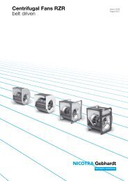
Smoke Extract Fans Entrauchungsventilatoren - Nicotra Industrial Fans
Smoke Extract Fans Entrauchungsventilatoren - Nicotra Industrial Fans
Smoke Extract Fans Entrauchungsventilatoren - Nicotra Industrial Fans
Erfolgreiche ePaper selbst erstellen
Machen Sie aus Ihren PDF Publikationen ein blätterbares Flipbook mit unserer einzigartigen Google optimierten e-Paper Software.
<strong>Entrauchungsventilatoren</strong> / Beschreibung<br />
RER ..-0200/-1600, 400 °C – 120 min.<br />
<strong>Smoke</strong> <strong>Extract</strong> <strong>Fans</strong> / Description<br />
Leistungsmessung<br />
Die Kennlinien zeigen die Totaldruckerhöhung p F als<br />
Funktion des Volumenstromes q V bei doppelt logarithmischer<br />
Netzteilung. Die Drossellinien (Widerstandsparabeln)<br />
erscheinen hierbei als Geraden.<br />
Der an den Drossellinien angeschriebene Wirkungsgrad<br />
gilt nur für die maximal zulässige<br />
Ventilatordrehzahl N max ; er verringert sich mit<br />
abnehmender Ventilatordrehzahl entsprechend<br />
dem Faktor f h . Dieser Faktor ist in den Kennfeldern<br />
auf der ganz rechts dargestellten vertikalen Skala<br />
abzulesen.<br />
Die tatsächlichen Wirkungsgrade für Ventilatordrehzahlen<br />
kleiner n max errechnen sich als Produkt aus<br />
dem bei N max abgelesenen Wirkungsgrad multipliziert<br />
mit dem der jeweiligen Ventilatordrehzahl entsprechenden<br />
Faktor f h (Ablesewert rechte Skalenleiste).<br />
Performance data<br />
The curves show the total pressure rise p F as a function<br />
of the volume flow rate q V plotted logarithmically.<br />
System resistance efficiency curves are then represented<br />
by straight lines.<br />
The degree of efficiency marked on the constant<br />
system lines is only valid at the maximum permitted<br />
rotational speed of fan N max ; it decreases with<br />
diminishing rotational speed indicated by the factor<br />
f h . This factor can be read off the vertical scale<br />
given on the far right of the curves.<br />
The actual degrees of efficiency for speeds lower<br />
nmax are calculated by multiplying the efficiency at<br />
N max by the factor f h for the appropriate speed.<br />
p a - gp<br />
r 1 = ——— = 1.2 kg/m³<br />
R W × T 1<br />
r II<br />
p FII = p FI ——<br />
1.2<br />
r II<br />
P II = P t ——<br />
1.2<br />
RER ..-0200/-1000<br />
p sF = p F - f pd × p d2<br />
RER 13-1120/-1600<br />
p sF = p F - p d2<br />
P N = P a × f p<br />
P a m 1.1 kW f p = 1.30<br />
P a L 1.1 m 2.2 kW f p = 1.25<br />
P a L 2.2 m 5.5 kW f p = 1.20<br />
P a L 5.5 m 11 kW f p = 1.15<br />
P a L 11 m 45 kW f p = 1.125<br />
P a L 45 kW f p = 1.10<br />
J × N 2<br />
t A = 8 ——— × 10 -6<br />
P N<br />
Die Kennlinien beziehen sich auf eine Dichte r 1 des<br />
Fördermediums am Ventilatoreintritt:<br />
Proportional mit der Dichte r 1 verändert sich die Druckerhöhung<br />
und die Antriebsleistung.<br />
Die Katalogdaten sind dann wie folgt zu korrigieren:<br />
I = Katalogangabe<br />
II = bei veränderter Eintrittsdichte<br />
p a = Luftdruck oder Barometerstand in Pa<br />
gp = Differenz des statischen Druckes zwischen Ventilatoreintritt<br />
und Versuchsraum<br />
R W = Gaskonstante der feuchten Luft [P 288 J/kg×K]<br />
T 1 = Thermodynamische Temperatur am Ventilatoreintritt<br />
[T 1 =273+t 1 ] in K<br />
t 1 = Lufttemperatur in °C<br />
Die Strömungsgeschwindigkeit v m2 und der dynamische<br />
Druck p d2 sind auf den Flanschquerschnitt am<br />
Ventilator-Austritt bezogen.<br />
Die statische Druckerhöhung p sF bei angeschlossenem<br />
druckseitigem Kanal ergibt sich daher aus der<br />
Beziehung:<br />
Ist druckseitig kein Kanal angeschlossen, bleibt der<br />
Sprungdiffusor ohne Wirkung.<br />
Die Druckerhöhung des frei ausblasenden Ventilators<br />
p sF errechnet sich dann nach den Beziehungen:<br />
Der Korrekturfaktor f pd für den dynamischen Druck ist<br />
dabei aus dem Kennfeld der jeweiligen Baugröße zu<br />
entnehmen.<br />
Für die Bestimmung der erforderlichen Motor-Nennleistung<br />
P N muss die Antriebsleistung bezogen auf<br />
die Ventilatorwelle P a um einen Sicherheitszuschlag<br />
für Riementriebsverluste und Drehzahlabweichungen<br />
erhöht werden.<br />
Der Faktor f p muss geschätzt werden. Als Richtwert<br />
werden nebenstehende Zahlenwerte vorgeschlagen.<br />
Bei der Auswahl des richtigen Antriebsmotors muss<br />
auch überprüft werden, ob aufgrund der zu beschleunigenden<br />
großen Massen die Anlaufzeit noch in den<br />
zulässigen Grenzen bleibt.<br />
Die Anlaufzeit kann näherungsweise nach folgender<br />
Formel bestimmt werden, darin bedeuten:<br />
t A = Anlaufzeit in s<br />
J = Massenträgheitsmoment in kgm²<br />
N = Drehzahl des Ventilators in 1/min<br />
P N = Nennleistung Motor in kW<br />
Ist t A größer als die vom Motorhersteller genannte<br />
max. Anlaufzeit bzw. größer als die Auslösezeit eines<br />
Motorschutzschalters, dann muss ein stärkerer Motor<br />
eingesetzt werden oder der Schutzschalter ist für<br />
Schwer-Anlauf auszulegen.<br />
The curves are represented with a reference density<br />
of:<br />
The pressure and impeller input power are directly proportional<br />
to density r 1 .<br />
They can be converted as follows:<br />
I = Catalogue<br />
II = Other Density<br />
p a = air pressure or barometer reading in Pa<br />
gp = difference of the static pressure between fan inlet and test<br />
site<br />
R W = Gas specific constant [P 288 J/kg×K]<br />
T 1 = Thermodynamic temperature at fan inlet [T 1 =273+t 1 ] in K<br />
t 1 = air temp. in °C<br />
Outlet velocity v m2 and the dynamic pressure p d2 refer<br />
to the flanged cross section area at the fan outlet.<br />
The increase in static pressure p sF when a duct is<br />
attached to the discharge can be calculated from the<br />
equation:<br />
Where no duct is fitted there is no static regain.<br />
The increase in pressure p sF can be calculated from p F<br />
formula:<br />
The correction factor fpd for the dynamic pressure can<br />
be obtained from the curve of the respective size.<br />
To determine the motor rating P N , the fan absorbed<br />
shaft power Pa must be increased by a factor f p to<br />
accommodate belt drive losses etc.<br />
The factor f p is an estimated value. As an approximate<br />
value, the figures at the side are suggested.<br />
When selecting the motor, the start up time must be<br />
within permitted limits. The start up time can be worked<br />
Out approximately according to the following formula,<br />
where:<br />
t A = acceleration time in seconds<br />
J = moment of inertia in kgm²<br />
N = fan speed in rpm<br />
P N = motor rating in kW<br />
If t A exceeds the motor manufacturer‘s recommendation,<br />
a larger motor or high-torque machine must be<br />
used. If tA exceeds the trip time of the starting gear, a<br />
longer delay must be used.<br />
129


