Smoke Extract Fans Entrauchungsventilatoren - Nicotra Industrial Fans
Smoke Extract Fans Entrauchungsventilatoren - Nicotra Industrial Fans Smoke Extract Fans Entrauchungsventilatoren - Nicotra Industrial Fans
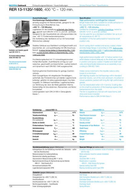
Entrauchungsventilatoren / Ausschreibungen RER 13-1120/-1600, 400 °C – 120 min. Smoke Extract Fans / Specifications Ausschreibungen Hochleistungs-Radialventilator rotavent einseitig saugend mit Riemenantrieb, geeignet für die Entrauchung im Brandfall bis max. +400 °C – 120 Minuten, zugelassen für die Aufstellung außerhalb des Gebäudes, geprüft nach DIN EN 12101-3, und CE- zertifiziert. Geeignet für den Dauerbetrieb als Lüftungsventilator bis max. +80 °C Fördermediumstemperatur. Die Aufstellung des Ventilators ist nur mit horizontaler Motorachse zulässig! Specification High performance centrifugal fan rotavent Single intake belt drive, suitable for smoke extraction in the case of fire for temperatures up to +400 °C – 120 minutes, Certified for installation outside of buildings, tested to DIN EN 12101-3, and CE certified. Can be used for as a standard ventilation fan up to an air temperature of +80 °C. Installation of the fan authorised for horizontal shaft position only. Ventilator und Zubehör geprüft nach EN 12101-3. EG-Konformitätszertifikat: 0036 CPD RG01 06 Fan and accessories tested to EN 12101-3 Certificate of EC conformity: 0036 CPD RG01 06 Stabiles Gehäuse aus Stahlblech schrittgeschweißt und beschichtet, ein- und austrittsseitig mit DIN Anschlussflansch. In einer Achse teilbar (2 Segmente)-Bg. 1120; bzw. in zwei Achsen teilbar (4 Segmente) Bg. 1250, 1400 und 1600. Hochleistungslaufrad mit 12 rückwärtsgekrümmten Hohlprofilschaufeln, Austrittskante schräg zur Laufradachse, geschweißt und beschichtet. Laufrad statisch und dynamisch nach DIN ISO 1940 ausgewuchtet. Optimal geformte Einströmdüse für geringe Zuströmverluste. Steh-Gussgehäuse mit eingebauten Pendellagern, außerhalb des Förderstromes auf stabiler Lagerkonsole befestigt, gefettet mit alterungsbeständigem Hochleistungsfett, im Stillstand nachfettbar. Lagerkühlscheibe zur Abführung der über die Welle geleiteten Wärme. Serienmäßig mit Grundrahmen, Riementrieb und Motor komplettiert. Leistungsdaten nach DIN 24166 in Genauigkeitsklasse 1. Scroll casing stitch welded and epoxy coated, intake and discharge flange in according to DIN. Split on one axis (2segments) Size 1120, or split in two axis (4 segments) Sizes 1250, 1400, 1600. High performance impeller with 12 hollow section true airfoil blades inclined obliquely to the shaft axis, welded in position and epoxy coated. Impeller and shaft statically and dynamically balanced as an assembly in according to DIN ISO 1940. Intake cones matched to the impeller reduce entry losses to a minimum. Self aligning double row ball bearings within standard plummer blocks, out of the main airstream, mounted on robust pedestal, packed with long life high performance grease. Can be relubricated when not in service. Cooling disk on the shaft for protection of the bearings against heat transmissions from the shaft. The fan is supplied as a full set with base frame, belt drive and motor included. Performance data to DIN 24166 Class 1. Ventilatortyp rotavent RER 13- Volumenstrom Totaldruckerhöhung q V = . . . . . . . . . . . . . . . . m 3/ h p F = . . . . . . . . . . . . . . . . Pa Druckerhöhung (frei ausblasend) p sF = . . . . . . . . . . . . . . . . Pa Dichte im Eintritt r 1 = . . . . . . . . . . . . . . . . °C Fördermediums-Temperatur t = . . . . . . . . . . . . . . . . °C Antriebsleistung P a = . . . . . . . . . . . . . . . . kW Wirkungsgrad (h a ) = . . . . . . . . . . . . . . . . % A-Schallleistungspegel L WA = . . . . . . . . . . . . . . . . dB Drehzahl N = . . . . . . . . . . . . . . . . 1/min Gewicht m = . . . . . . . . . . . . . . . . kg Type rotavent RER 13- Volume Total Pressure increase q V = . . . . . . . . . . . . . . . . m 3/ h p F = . . . . . . . . . . . . . . . . Pa Pressure increase (free discharge) p sF = . . . . . . . . . . . . . . . . Pa Density at Inlet r 1 = . . . . . . . . . . . . . . . . °C Temperature of Gas Medium t = . . . . . . . . . . . . . . . . °C Shaft Power P a = . . . . . . . . . . . . . . . . kW Efficiency (h a ) = . . . . . . . . . . . . . . . . % A-Sound Power Level L WA = . . . . . . . . . . . . . . . . dB Speed N = . . . . . . . . . . . . . . . . 1/min Weight m = . . . . . . . . . . . . . . . . kg 128 Sonderausstattung (gegen Mehrpreis) Isoliergehäuse (für die Aufstellung innerhalb des Gebäudes – außerhalb des Brandraumes) Motorschutzdach für Außenaufstellung Riemenschutz allseitig geschlossen Volumenstrom-Messvorrichtung IMV 11 (K10) Nachschmiereinrichtung für Nachschmierung bei Betrieb - IWN 01 - Shell Alvania RL3 Korrosionsschutzklasse K90 Lagerüberwachungssystem SPM Zubehör (gegen Mehrpreis) Ansaugflansch Ansaugstutzen bis +600 °C (ZKE 33) Anschlussflansch Anschlussstutzen bis +600 °C (ZKE 34) Berührungsschutzgitter – Austrittsseite Feder-Schwingungsdämpfer Special fittings (at extra cost) Insulation housing (for installation inside of buildings – outside room with fire risk) Motor protection hood for outside installation Belt guard Volumeter IMV 11 (K10) Relubrication in operation - IWN 01 - Shell Alvania RL3 grease Special coating Class K90 Bearing monitoring system type SPM Accessories (at extra cost) Inlet Flange Inlet Connection (flexible) up to +600 °C (ZKE 33) Discharge Flange Discharge Connection (flexible) up to +600 °C (ZKE 34) Discharge Guard Spring diffusers
Entrauchungsventilatoren / Beschreibung RER ..-0200/-1600, 400 °C – 120 min. Smoke Extract Fans / Description Leistungsmessung Die Kennlinien zeigen die Totaldruckerhöhung p F als Funktion des Volumenstromes q V bei doppelt logarithmischer Netzteilung. Die Drossellinien (Widerstandsparabeln) erscheinen hierbei als Geraden. Der an den Drossellinien angeschriebene Wirkungsgrad gilt nur für die maximal zulässige Ventilatordrehzahl N max ; er verringert sich mit abnehmender Ventilatordrehzahl entsprechend dem Faktor f h . Dieser Faktor ist in den Kennfeldern auf der ganz rechts dargestellten vertikalen Skala abzulesen. Die tatsächlichen Wirkungsgrade für Ventilatordrehzahlen kleiner n max errechnen sich als Produkt aus dem bei N max abgelesenen Wirkungsgrad multipliziert mit dem der jeweiligen Ventilatordrehzahl entsprechenden Faktor f h (Ablesewert rechte Skalenleiste). Performance data The curves show the total pressure rise p F as a function of the volume flow rate q V plotted logarithmically. System resistance efficiency curves are then represented by straight lines. The degree of efficiency marked on the constant system lines is only valid at the maximum permitted rotational speed of fan N max ; it decreases with diminishing rotational speed indicated by the factor f h . This factor can be read off the vertical scale given on the far right of the curves. The actual degrees of efficiency for speeds lower nmax are calculated by multiplying the efficiency at N max by the factor f h for the appropriate speed. p a - gp r 1 = ——— = 1.2 kg/m³ R W × T 1 r II p FII = p FI —— 1.2 r II P II = P t —— 1.2 RER ..-0200/-1000 p sF = p F - f pd × p d2 RER 13-1120/-1600 p sF = p F - p d2 P N = P a × f p P a m 1.1 kW f p = 1.30 P a L 1.1 m 2.2 kW f p = 1.25 P a L 2.2 m 5.5 kW f p = 1.20 P a L 5.5 m 11 kW f p = 1.15 P a L 11 m 45 kW f p = 1.125 P a L 45 kW f p = 1.10 J × N 2 t A = 8 ——— × 10 -6 P N Die Kennlinien beziehen sich auf eine Dichte r 1 des Fördermediums am Ventilatoreintritt: Proportional mit der Dichte r 1 verändert sich die Druckerhöhung und die Antriebsleistung. Die Katalogdaten sind dann wie folgt zu korrigieren: I = Katalogangabe II = bei veränderter Eintrittsdichte p a = Luftdruck oder Barometerstand in Pa gp = Differenz des statischen Druckes zwischen Ventilatoreintritt und Versuchsraum R W = Gaskonstante der feuchten Luft [P 288 J/kg×K] T 1 = Thermodynamische Temperatur am Ventilatoreintritt [T 1 =273+t 1 ] in K t 1 = Lufttemperatur in °C Die Strömungsgeschwindigkeit v m2 und der dynamische Druck p d2 sind auf den Flanschquerschnitt am Ventilator-Austritt bezogen. Die statische Druckerhöhung p sF bei angeschlossenem druckseitigem Kanal ergibt sich daher aus der Beziehung: Ist druckseitig kein Kanal angeschlossen, bleibt der Sprungdiffusor ohne Wirkung. Die Druckerhöhung des frei ausblasenden Ventilators p sF errechnet sich dann nach den Beziehungen: Der Korrekturfaktor f pd für den dynamischen Druck ist dabei aus dem Kennfeld der jeweiligen Baugröße zu entnehmen. Für die Bestimmung der erforderlichen Motor-Nennleistung P N muss die Antriebsleistung bezogen auf die Ventilatorwelle P a um einen Sicherheitszuschlag für Riementriebsverluste und Drehzahlabweichungen erhöht werden. Der Faktor f p muss geschätzt werden. Als Richtwert werden nebenstehende Zahlenwerte vorgeschlagen. Bei der Auswahl des richtigen Antriebsmotors muss auch überprüft werden, ob aufgrund der zu beschleunigenden großen Massen die Anlaufzeit noch in den zulässigen Grenzen bleibt. Die Anlaufzeit kann näherungsweise nach folgender Formel bestimmt werden, darin bedeuten: t A = Anlaufzeit in s J = Massenträgheitsmoment in kgm² N = Drehzahl des Ventilators in 1/min P N = Nennleistung Motor in kW Ist t A größer als die vom Motorhersteller genannte max. Anlaufzeit bzw. größer als die Auslösezeit eines Motorschutzschalters, dann muss ein stärkerer Motor eingesetzt werden oder der Schutzschalter ist für Schwer-Anlauf auszulegen. The curves are represented with a reference density of: The pressure and impeller input power are directly proportional to density r 1 . They can be converted as follows: I = Catalogue II = Other Density p a = air pressure or barometer reading in Pa gp = difference of the static pressure between fan inlet and test site R W = Gas specific constant [P 288 J/kg×K] T 1 = Thermodynamic temperature at fan inlet [T 1 =273+t 1 ] in K t 1 = air temp. in °C Outlet velocity v m2 and the dynamic pressure p d2 refer to the flanged cross section area at the fan outlet. The increase in static pressure p sF when a duct is attached to the discharge can be calculated from the equation: Where no duct is fitted there is no static regain. The increase in pressure p sF can be calculated from p F formula: The correction factor fpd for the dynamic pressure can be obtained from the curve of the respective size. To determine the motor rating P N , the fan absorbed shaft power Pa must be increased by a factor f p to accommodate belt drive losses etc. The factor f p is an estimated value. As an approximate value, the figures at the side are suggested. When selecting the motor, the start up time must be within permitted limits. The start up time can be worked Out approximately according to the following formula, where: t A = acceleration time in seconds J = moment of inertia in kgm² N = fan speed in rpm P N = motor rating in kW If t A exceeds the motor manufacturer‘s recommendation, a larger motor or high-torque machine must be used. If tA exceeds the trip time of the starting gear, a longer delay must be used. 129
- Seite 21 und 22: Entrauchungsventilatoren / Technisc
- Seite 23 und 24: Entrauchungsventilatoren / Technisc
- Seite 25 und 26: Entrauchungsventilatoren / Technisc
- Seite 27 und 28: Entrauchungsventilatoren / Ausschre
- Seite 29 und 30: REM BU-2528/-8090, 600 °C - 120 mi
- Seite 31 und 32: Vielfalt hat einen Namen: RER rotav
- Seite 33 und 34: Entrauchungsventilatoren / Technisc
- Seite 35 und 36: Entrauchungsventilatoren / Technisc
- Seite 37 und 38: Entrauchungsventilatoren / Technisc
- Seite 39 und 40: Entrauchungsventilatoren / Technisc
- Seite 41 und 42: Entrauchungsventilatoren / Technisc
- Seite 43 und 44: Entrauchungsventilatoren / Technisc
- Seite 45 und 46: Entrauchungsventilatoren / Technisc
- Seite 47 und 48: Entrauchungsventilatoren / Technisc
- Seite 49 und 50: Entrauchungsventilatoren / Technisc
- Seite 51 und 52: Entrauchungsventilatoren / Technisc
- Seite 53 und 54: Entrauchungsventilatoren / Technisc
- Seite 55 und 56: Entrauchungsventilatoren / Technisc
- Seite 57 und 58: Entrauchungsventilatoren / Technisc
- Seite 59 und 60: Entrauchungsventilatoren / Technisc
- Seite 61 und 62: Entrauchungsventilatoren / Technisc
- Seite 63 und 64: Entrauchungsventilatoren / Technisc
- Seite 65 und 66: Entrauchungsventilatoren / Technisc
- Seite 67 und 68: Entrauchungsventilatoren / Technisc
- Seite 69 und 70: Entrauchungsventilatoren / Technisc
- Seite 71: Entrauchungsventilatoren / Ausschre
- Seite 75 und 76: Entrauchungsventilatoren / Beschrei
- Seite 77 und 78: Entrauchungsventilatoren / Beschrei
- Seite 79 und 80: Entrauchungsventilatoren / Anwendun
- Seite 81 und 82: Entrauchungsventilatoren / Zubehör
- Seite 83 und 84: Entrauchungsventilatoren / Zubehör
- Seite 85 und 86: Entrauchungsventilatoren / Zubehör
- Seite 87 und 88: Rauchschutz-Druckanlagen Positive P
- Seite 89 und 90: Entrauchungsventilatoren / Zubehör
- Seite 91 und 92: Entrauchungsventilatoren / Zubehör
- Seite 93 und 94: Entrauchungsventilatoren / Zubehör
- Seite 95 und 96: Entrauchungsventilatoren / Zubehör
- Seite 97 und 98: Entrauchungsventilatoren / Zubehör
- Seite 99 und 100: 0 Entrauchungsventilatoren / Zubeh
- Seite 101 und 102: Entrauchungsventilatoren / Zubehör
- Seite 103 und 104: Entrauchungsventilatoren / Beschrei
- Seite 105 und 106: Description Entrauchungsventilatore
- Seite 107 und 108: Entrauchungsventilatoren / Beschrei
- Seite 109 und 110: Entrauchungsventilatoren / Beschrei
- Seite 111 und 112: Entrauchungsventilatoren / Beschrei
- Seite 113 und 114: Entrauchungsventilatoren Notizen Sm
- Seite 115: Nicotra Gebhardt weltweit worldwide
<strong>Entrauchungsventilatoren</strong> / Ausschreibungen<br />
RER 13-1120/-1600, 400 °C – 120 min.<br />
<strong>Smoke</strong> <strong>Extract</strong> <strong>Fans</strong> / Specifications<br />
Ausschreibungen<br />
Hochleistungs-Radialventilator rotavent<br />
einseitig saugend mit Riemenantrieb, geeignet für die<br />
Entrauchung im Brandfall bis max.<br />
+400 °C – 120 Minuten,<br />
zugelassen für die Aufstellung außerhalb des Gebäudes,<br />
geprüft nach DIN EN 12101-3, und CE- zertifiziert.<br />
Geeignet für den Dauerbetrieb als Lüftungsventilator bis<br />
max. +80 °C Fördermediumstemperatur.<br />
Die Aufstellung des Ventilators ist nur mit horizontaler<br />
Motorachse zulässig!<br />
Specification<br />
High performance centrifugal fan rotavent<br />
Single intake belt drive, suitable for smoke extraction in<br />
the case of fire for temperatures up to<br />
+400 °C – 120 minutes,<br />
Certified for installation outside of buildings, tested to<br />
DIN EN 12101-3, and CE certified.<br />
Can be used for as a standard ventilation fan up to an<br />
air temperature of +80 °C.<br />
Installation of the fan authorised for horizontal shaft<br />
position only.<br />
Ventilator und Zubehör geprüft<br />
nach EN 12101-3.<br />
EG-Konformitätszertifikat:<br />
0036 CPD RG01 06<br />
Fan and accessories tested<br />
to EN 12101-3<br />
Certificate of EC conformity:<br />
0036 CPD RG01 06<br />
Stabiles Gehäuse aus Stahlblech schrittgeschweißt und<br />
beschichtet, ein- und austrittsseitig mit DIN Anschlussflansch.<br />
In einer Achse teilbar (2 Segmente)-Bg. 1120;<br />
bzw. in zwei Achsen teilbar (4 Segmente) Bg. 1250,<br />
1400 und 1600.<br />
Hochleistungslaufrad mit 12 rückwärtsgekrümmten<br />
Hohlprofilschaufeln, Austrittskante schräg zur Laufradachse,<br />
geschweißt und beschichtet. Laufrad statisch<br />
und dynamisch nach DIN ISO 1940 ausgewuchtet.<br />
Optimal geformte Einströmdüse für geringe Zuströmverluste.<br />
Steh-Gussgehäuse mit eingebauten Pendellagern,<br />
außerhalb des Förderstromes auf stabiler Lagerkonsole<br />
befestigt, gefettet mit alterungsbeständigem Hochleistungsfett,<br />
im Stillstand nachfettbar. Lagerkühlscheibe<br />
zur Abführung der über die Welle geleiteten Wärme.<br />
Serienmäßig mit Grundrahmen, Riementrieb und Motor<br />
komplettiert.<br />
Leistungsdaten nach DIN 24166 in Genauigkeitsklasse<br />
1.<br />
Scroll casing stitch welded and epoxy coated, intake<br />
and discharge flange in according to DIN. Split on one<br />
axis (2segments) Size 1120, or split in two axis (4 segments)<br />
Sizes 1250, 1400, 1600.<br />
High performance impeller with 12 hollow section true<br />
airfoil blades inclined obliquely to the shaft axis, welded<br />
in position and epoxy coated. Impeller and shaft statically<br />
and dynamically balanced as an assembly in according<br />
to DIN ISO 1940.<br />
Intake cones matched to the impeller reduce entry<br />
losses to a minimum.<br />
Self aligning double row ball bearings within standard<br />
plummer blocks, out of the main airstream, mounted on<br />
robust pedestal, packed with long life high performance<br />
grease.<br />
Can be relubricated when not in service. Cooling disk<br />
on the shaft for protection of the bearings against heat<br />
transmissions from the shaft.<br />
The fan is supplied as a full set with base frame, belt<br />
drive and motor included.<br />
Performance data to DIN 24166 Class 1.<br />
Ventilatortyp rotavent RER 13-<br />
Volumenstrom<br />
Totaldruckerhöhung<br />
q V = . . . . . . . . . . . . . . . . m 3/ h<br />
p F = . . . . . . . . . . . . . . . . Pa<br />
Druckerhöhung<br />
(frei ausblasend)<br />
p sF = . . . . . . . . . . . . . . . . Pa<br />
Dichte im Eintritt r 1 = . . . . . . . . . . . . . . . . °C<br />
Fördermediums-Temperatur t = . . . . . . . . . . . . . . . . °C<br />
Antriebsleistung<br />
P a = . . . . . . . . . . . . . . . . kW<br />
Wirkungsgrad (h a ) = . . . . . . . . . . . . . . . . %<br />
A-Schallleistungspegel L WA = . . . . . . . . . . . . . . . . dB<br />
Drehzahl<br />
N = . . . . . . . . . . . . . . . . 1/min<br />
Gewicht<br />
m = . . . . . . . . . . . . . . . . kg<br />
Type rotavent RER 13-<br />
Volume<br />
Total Pressure increase<br />
q V = . . . . . . . . . . . . . . . . m 3/ h<br />
p F = . . . . . . . . . . . . . . . . Pa<br />
Pressure increase<br />
(free discharge)<br />
p sF = . . . . . . . . . . . . . . . . Pa<br />
Density at Inlet r 1 = . . . . . . . . . . . . . . . . °C<br />
Temperature of Gas Medium t = . . . . . . . . . . . . . . . . °C<br />
Shaft Power<br />
P a = . . . . . . . . . . . . . . . . kW<br />
Efficiency (h a ) = . . . . . . . . . . . . . . . . %<br />
A-Sound Power Level L WA = . . . . . . . . . . . . . . . . dB<br />
Speed<br />
N = . . . . . . . . . . . . . . . . 1/min<br />
Weight<br />
m = . . . . . . . . . . . . . . . . kg<br />
128<br />
Sonderausstattung (gegen Mehrpreis)<br />
Isoliergehäuse (für die Aufstellung innerhalb des Gebäudes – außerhalb<br />
des Brandraumes)<br />
Motorschutzdach für Außenaufstellung<br />
Riemenschutz allseitig geschlossen<br />
Volumenstrom-Messvorrichtung IMV 11 (K10)<br />
Nachschmiereinrichtung für Nachschmierung bei Betrieb<br />
- IWN 01 - Shell Alvania RL3<br />
Korrosionsschutzklasse K90<br />
Lagerüberwachungssystem SPM<br />
Zubehör (gegen Mehrpreis)<br />
Ansaugflansch<br />
Ansaugstutzen bis +600 °C (ZKE 33)<br />
Anschlussflansch<br />
Anschlussstutzen bis +600 °C (ZKE 34)<br />
Berührungsschutzgitter – Austrittsseite<br />
Feder-Schwingungsdämpfer<br />
Special fittings (at extra cost)<br />
Insulation housing (for installation inside of buildings – outside room<br />
with fire risk)<br />
Motor protection hood for outside installation<br />
Belt guard<br />
Volumeter IMV 11 (K10)<br />
Relubrication in operation<br />
- IWN 01 - Shell Alvania RL3 grease<br />
Special coating Class K90<br />
Bearing monitoring system type SPM<br />
Accessories (at extra cost)<br />
Inlet Flange<br />
Inlet Connection (flexible) up to +600 °C (ZKE 33)<br />
Discharge Flange<br />
Discharge Connection (flexible) up to +600 °C (ZKE 34)<br />
Discharge Guard<br />
Spring diffusers


