Profil Lineareinheit PLZ-II Profile linear unit PLZ-II
Profil Lineareinheit PLZ-II Profile linear unit PLZ-II
Profil Lineareinheit PLZ-II Profile linear unit PLZ-II

Sie wollen auch ein ePaper? Erhöhen Sie die Reichweite Ihrer Titel.
YUMPU macht aus Druck-PDFs automatisch weboptimierte ePaper, die Google liebt.
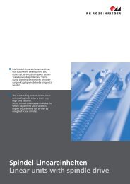
Der Vorteil der <strong>Lineareinheit</strong>en mit<br />
Zahnriemenantrieb liegt in der<br />
Möglichkeit, Lasten mit besonders<br />
hohen Geschwindigkeiten zu verfahren.<br />
The advantage of <strong>linear</strong> <strong>unit</strong>s with<br />
timing belt drive lies in the fact<br />
that loads can be moved at a very<br />
high speed.<br />
Zahnriemen-<strong>Lineareinheit</strong>en<br />
Linear <strong>unit</strong>s with timing belt drive<br />
<strong>II</strong>I - 1
Zahnriemen-<strong>Lineareinheit</strong>en<br />
Linear <strong>unit</strong>s with timing belt drive<br />
<strong>Profil</strong> <strong>Lineareinheit</strong> <strong>PLZ</strong>-<strong>II</strong><br />
<strong>Profil</strong>e <strong>linear</strong> <strong>unit</strong> <strong>PLZ</strong>-<strong>II</strong><br />
Seite 4-25<br />
• Führungsprofil und Schlitten<br />
aus stranggepressten Aluminium<br />
• BLOCAN ® -Nutgeometrie im<br />
Führungsschlitten<br />
• Einsatz breiter Zahnriemen<br />
bis 40 mm<br />
• Schlittenführung mittels<br />
Laufrollen<br />
• Externe Führungswellenschmierung<br />
Page 4-25<br />
• guide profile and guide<br />
table made of extruded<br />
aluminium<br />
• guide table with BLOCAN ®<br />
slot geometry<br />
• wide timing belt<br />
(up to 40 mm)<br />
• guide table fitted with<br />
rollers<br />
• external guide shaft lubrication<br />
<strong>Profil</strong> <strong>Lineareinheit</strong> <strong>PLZ</strong>-i-<strong>II</strong><br />
<strong>Profil</strong>e <strong>linear</strong> <strong>unit</strong> <strong>PLZ</strong>-i-<strong>II</strong><br />
Seite 14-25<br />
• Innenliegender Zahnriemen<br />
(Riemen verfährt im Führungsprofil)<br />
• Aufbau ähnlich <strong>PLZ</strong><br />
Page 14-25<br />
• inside timing belt (the timing<br />
belt is carried inside<br />
the guide profile)<br />
• design similar to <strong>PLZ</strong><br />
<strong>Profil</strong> <strong>Lineareinheit</strong> SQZ-<strong>II</strong><br />
<strong>Profil</strong>e <strong>linear</strong> <strong>unit</strong> SQZ-<strong>II</strong><br />
Seite 26-41<br />
• Führungskörper aus<br />
BLOCAN ® -Nutprofil<br />
• Externe Führungswellenschmierung<br />
• Umfangreiches Zubehör<br />
(BLOCAN ® -Zubehör lässt sich<br />
an Führungsschlitten und<br />
Führungsprofil befestigen)<br />
Page 26-41<br />
• guide body made of<br />
BLOCAN ® profile<br />
• external guide shaft<br />
lubrication<br />
• wide range of accessories<br />
(BLOCAN ® accessories can be<br />
fixed onto guide table and<br />
guide profile)<br />
<strong>Profil</strong> <strong>Lineareinheit</strong> SQ-<strong>II</strong> MT<br />
<strong>Profil</strong>e <strong>linear</strong> <strong>unit</strong> SQ-<strong>II</strong> MT<br />
Seite 42-55<br />
• für große Hublängen<br />
bis 18 m<br />
• Führungsprofil aus<br />
BLOCAN ® -Nutprofil<br />
• Umlenkblock und Antrieb<br />
verfährt mit dem<br />
Führungsschlitten<br />
Page 42-55<br />
• travel lengths up to<br />
18 m possible<br />
• guide body made of<br />
BLOCAN ® profile<br />
• pulley box with drive<br />
pin moves together<br />
with guide table<br />
<strong>II</strong>I - 2<br />
RK Rose+Krieger GmbH Postfach 15 64 D-32375 Minden
I<br />
<strong>Profil</strong> <strong>Lineareinheit</strong> LMZ<br />
<strong>Profil</strong>e <strong>linear</strong> <strong>unit</strong> LMZ<br />
Seite 56-67<br />
• Robustes Linearmodul mit<br />
Zahnriemenantrieb<br />
• BLOCAN ® -Führungsprofil aus<br />
F-100x100<br />
• Hohe Tragkraft<br />
• Laufrollenführung auf gehärteten<br />
Wellen Ø20 mm<br />
Page 56-67<br />
• stable <strong>linear</strong> module with timing<br />
belt drive<br />
• guide profile made of<br />
BLOCAN ® profile F-100x100<br />
• high load capacity<br />
• roller guiding on Ø20 mm<br />
hardened shafts<br />
<strong>II</strong><br />
<strong>II</strong>I<br />
RK DuoLine Z<br />
RK DuoLine Z<br />
Seite 68-81<br />
• Wahlweise Laufrollen- oder<br />
Kugelschienenführung<br />
• Im <strong>Profil</strong> gekapseltes Führungskonzept<br />
• Zentrale Wartungsöffnung<br />
• Kompakte und flache Bauweise<br />
Page 68-81<br />
• optional roller guide or ball<br />
rail system<br />
• guide system included in the<br />
profile<br />
• central opening for maintenance<br />
• small and flat construction<br />
IV<br />
<strong>Profil</strong> <strong>Lineareinheit</strong> DGZ<br />
<strong>Profil</strong>e <strong>linear</strong> <strong>unit</strong> DGZ<br />
Seite 82-93<br />
• Geschlossener Führungsschlitten<br />
zur Aufnahme hoher<br />
Momente<br />
• Verteilung der Auftretenden<br />
Kräfte auf 8 spielfrei einstellbare<br />
Laufrollen<br />
• Breiter Zahnriemen für maximale<br />
Kraftaufnahme in axialer<br />
Richtung<br />
Page 82-93<br />
• "closed" guide table and 4<br />
guide shafts to support high<br />
moments<br />
• Load distribution on 8 rollers,<br />
adjustable free from<br />
play<br />
• wide timing belt to guarantee<br />
a maximum load support<br />
in the axial direction<br />
V<br />
MultiLine <strong>II</strong><br />
MultiLine <strong>II</strong><br />
Seite 94-107<br />
• Wahlweise Laufrollen- oder<br />
Kugelschienenführung<br />
• Breiter Zahnriemen (60mm)<br />
zur Aufnahme hoher axialer<br />
Kräfte<br />
• Führungsprofil aus<br />
BLOCAN ® -Nutprofil<br />
• Als Rollführung lieferbar<br />
Page 94-107<br />
• option between roller guide<br />
and ball rail version<br />
• wider drive belt (60 mm) for<br />
higher axial forces<br />
• guide body made of<br />
BLOCAN ® profile<br />
• also available as rolling<br />
guide<br />
VI<br />
V<strong>II</strong><br />
quad ® <strong>Lineareinheit</strong> EVT-Z<br />
quad ® <strong>linear</strong> <strong>unit</strong> EVT-Z<br />
D-LE 02/2004<br />
Seite 108-115<br />
• Resistent gegen Stöße und<br />
Vibrationen<br />
• Verschmutzungsresistente<br />
Führung<br />
• Einstellbares Spiel der Führungen<br />
• Hohe Lebensdauer<br />
• Korrosionsfrei<br />
Page 108-115<br />
• resistance to shock an<br />
vibrations<br />
• pollutions resistant guide<br />
• adjustable guides<br />
• high durability<br />
• corrosion free<br />
<strong>II</strong>I - 3<br />
V<strong>II</strong>I<br />
IX
<strong>Profil</strong> <strong>Lineareinheit</strong> <strong>PLZ</strong>-<strong>II</strong><br />
<strong>Profil</strong>e <strong>linear</strong> <strong>unit</strong> <strong>PLZ</strong>-<strong>II</strong><br />
BeiderEntwicklungdes<strong>PLZ</strong>-Führungsprofils wurdebesonderer<br />
Wert auf die Funktionalität gelegt. Das<br />
Strangpressprofil weist eine integrierte Aufnahme der<br />
Führungswelle, spezielle Nuten zur Befestigung von<br />
Klemmleisten und Näherungsschaltern sowie eine große<br />
Hohlkammer zur Durchführung eines breiten Zahnriemens<br />
auf.<br />
Die Merkmale und Abmessungen sind ähnlich der Spindeleinheit<br />
PLS-<strong>II</strong>, so dass die Einheiten auch in Kombination<br />
in einem Mehrachssystem optimal zusammenspielen.<br />
Eine weitere Ausführung bildet die <strong>PLZ</strong>-i-<strong>II</strong> mit einem<br />
im Führungsprofil verlaufenden Zahnriemen. Dieses<br />
Konzept bietet besonders in Umgebungen einen Vorteil,<br />
in denen keine Beeinflussung vom Antrieb (z.B. bei<br />
Vermeidung von Zahnriemenabrieb in Reinräumen)<br />
ausgehen darf.<br />
Functionality was the key word of the <strong>PLZ</strong> guide profile<br />
development. The extruded aluminium profile is<br />
characterized by its integrated guide shafts, its special<br />
slots aiming the fixation of clamping strips and<br />
connecting elements for proximity switch, as well as by<br />
a large opening permitting a large timing belt.<br />
Characteristics and dimensions are similar to the ones<br />
of the spindle <strong>unit</strong> PLS-<strong>II</strong>, which offers a good<br />
compatibility to multiple axis systems.<br />
The <strong>PLZ</strong>-i-<strong>II</strong> is another version, by which the timing belt<br />
runs inside of the guide profile. This concept is a<br />
particular advantage in environments forbidding any<br />
exterior influence (as for instance timing belt dust in<br />
clean-room conditions.)<br />
Merkmale<br />
• Baugrößen 30, 40, 50, 60 und 80 mm<br />
• Stranggepresster Führungsschlitten mit<br />
Befestigungsnuten<br />
• Federnd gelagertes Abstreifersystem<br />
• Laufrollenabdeckung<br />
• Rechts-/Links Ausführung und Variante mit<br />
innenliegendem Zahnriemen lieferbar<br />
Features<br />
• sizes 30, 40, 50, 60 and 80 mm<br />
• extruded guide table with fixation slots<br />
• spring loaded wipers<br />
• roller cover<br />
• righthand/lefthand version and variant with<br />
timing belt inside the guide profile also available<br />
<strong>II</strong>I - 4<br />
RK Rose+Krieger GmbH Postfach 15 64 D-32375 Minden
I<br />
Inhaltsverzeichnis<br />
Contents<br />
Technische Beschreibung<br />
Technical description<br />
<strong>II</strong><br />
Auslegung<br />
Specifications<br />
Seite 6 - 9<br />
Page 6 - 9<br />
<strong>II</strong>I<br />
<strong>PLZ</strong>-<strong>II</strong><br />
<strong>PLZ</strong>-<strong>II</strong><br />
• <strong>PLZ</strong>-<strong>II</strong><br />
• <strong>PLZ</strong>-<strong>II</strong> Rechts- / Links<br />
• <strong>PLZ</strong>-<strong>II</strong><br />
• <strong>PLZ</strong>-<strong>II</strong> righthand / lefthand<br />
IV<br />
Seite 10 - 13<br />
Page 10 - 13<br />
V<br />
<strong>PLZ</strong>-i-<strong>II</strong><br />
(innenliegender Zahnriemen)<br />
• <strong>PLZ</strong>-i-<strong>II</strong><br />
• <strong>PLZ</strong>-i-<strong>II</strong> Rechts- / Links<br />
Seite 14 - 17<br />
<strong>PLZ</strong>-i-<strong>II</strong><br />
(timing belt inside the guide<br />
profile)<br />
• <strong>PLZ</strong>-i-<strong>II</strong><br />
• <strong>PLZ</strong>-i-<strong>II</strong> righthand / lefthand<br />
Page 14 - 17<br />
VI<br />
V<strong>II</strong><br />
Zubehör<br />
Accessories<br />
Seite 18 - 25<br />
Page 18 - 25<br />
V<strong>II</strong>I<br />
IX<br />
D-LE 02/2003<br />
<strong>II</strong>I - 5
<strong>Profil</strong> <strong>Lineareinheit</strong> <strong>PLZ</strong>-<strong>II</strong><br />
<strong>Profil</strong>e <strong>linear</strong> <strong>unit</strong> <strong>PLZ</strong>-<strong>II</strong><br />
Technische Beschreibung<br />
Technical description<br />
Zwei parallel zueinander<br />
angeordnete Führungswellen<br />
(10) bilden zusammen<br />
mit einem speziellen<br />
Führungsprofil (3) den<br />
Grundkörper der <strong>Lineareinheit</strong><br />
<strong>PLZ</strong>-<strong>II</strong>.<br />
Über einen Zahnriemen<br />
(2) wird eine Rotationsbewegung<br />
in eine <strong>linear</strong>e<br />
Positionierbewegung des<br />
Führungsschlittens (12)<br />
umgewandelt.<br />
(Vergl. Seite 7)<br />
Two parallel guide shafts<br />
(10) form together with a<br />
special guide profile (3)<br />
the body of the <strong>linear</strong> <strong>unit</strong><br />
<strong>PLZ</strong>-<strong>II</strong>.<br />
A rotating movement is<br />
converted into the <strong>linear</strong><br />
movement of the guide<br />
Zahnriemen<br />
Timing belt<br />
GT-Zahnriemen mit<br />
Stahleinlage:<br />
Teilung: 5 mm<br />
Breite: 12 mm (<strong>PLZ</strong> 30)<br />
15 mm (<strong>PLZ</strong>-i 50)<br />
20 mm (<strong>PLZ</strong> 40<br />
<strong>PLZ</strong>-i 60<br />
25 mm (<strong>PLZ</strong> 50)<br />
30 mm (<strong>PLZ</strong>-i 80)<br />
GT-Zahnriemen mit<br />
Stahleinlage:<br />
Teilung: 8 mm<br />
Breite: 28 mm (<strong>PLZ</strong> 60)<br />
40 mm (<strong>PLZ</strong> 80)<br />
Teilung: 3 mm<br />
Breite: 6 mm (<strong>PLZ</strong>-i 30)<br />
9 mm (<strong>PLZ</strong>-i 40)<br />
GT timing belt with steel<br />
insert:<br />
pitch: 5 mm<br />
width: 12 mm (<strong>PLZ</strong> 30)<br />
15 mm (<strong>PLZ</strong>-i 50)<br />
20 mm (<strong>PLZ</strong> 40<br />
<strong>PLZ</strong>-i 60<br />
25 mm (<strong>PLZ</strong> 50)<br />
30 mm (<strong>PLZ</strong>-i 80)<br />
GT timing belt with steel<br />
insert:<br />
pitch: 8 mm<br />
width: 28 mm (<strong>PLZ</strong> 60)<br />
40 mm (<strong>PLZ</strong> 80)<br />
pitch: 3 mm<br />
width: 6 mm (<strong>PLZ</strong>-i 30)<br />
9 mm (<strong>PLZ</strong>-i 40)<br />
Umlenkungen<br />
Pulley boxes<br />
AlMgSi, schwarz pulverbeschichtet<br />
Anschlussflächen blank<br />
Führungsschlitten<br />
AlMgSi, black powder<br />
coated<br />
connection surface nonpainted<br />
Guide table<br />
Stranggepresstes Aluminium,<br />
hell eloxiert<br />
extruded aluminium,<br />
clear anodized<br />
Führungswellen<br />
Guide shafts<br />
Vergütungsstahl,<br />
induktiv gehärtet<br />
Oberfläche hartverchromt<br />
HRC 62<br />
heat-treated steel,<br />
inductively hardened<br />
surface hard-chrome<br />
plated HRC 62<br />
Lagerung<br />
Bearing<br />
Wellenlagerung:<br />
abgedichtete 1-reihige<br />
Rillenkugellager<br />
Führungsschlitten:<br />
4 abgedichtete Laufrollen<br />
(Aufbau entspricht<br />
2-reihigen Schrägkugellager)<br />
shaft bearing:<br />
single-row sealed grooved<br />
ball bearing<br />
guide table bearing:<br />
4 sealed rollers (corresponds<br />
to a two-row angular<br />
contact bearing)<br />
Befestigung der<br />
<strong>Lineareinheit</strong><br />
Fixation of the <strong>linear</strong><br />
<strong>unit</strong><br />
Mit Hilfe von Befestigungslaschen<br />
am Führungsprofil,<br />
sowie durch<br />
Verschraubung der Umlenkung<br />
mit dem Unterbau.<br />
Fixation by means of<br />
fixing plates or by screwingthepulleyboxonto<br />
existing constructions.<br />
<strong>II</strong>I - 6<br />
RK Rose+Krieger GmbH & Co. KG Postfach 15 64 D-32375 Minden
I<br />
<strong>II</strong><br />
<strong>II</strong>I<br />
14<br />
13<br />
5<br />
11<br />
12<br />
IV<br />
4<br />
10<br />
8<br />
9<br />
V<br />
7<br />
6<br />
Abbildung zeigt <strong>PLZ</strong>-<strong>II</strong> 60<br />
Illustration shows <strong>PLZ</strong>-<strong>II</strong> 60<br />
VI<br />
3<br />
2<br />
V<strong>II</strong><br />
1<br />
1 - Zahnriemenantrieb 8 - Laufrolle<br />
2 - Zahnriemen 9 - Führungswellenschmierung<br />
3 - Führungsprofil 10 - Schmiernippel (Führungswelle)<br />
4 - Filzabstreifer 11 - Führungswelle<br />
5 - Abdeckkappe 12 - Führungsschlitten<br />
6 - Zahnriemenspannsatz 13 - Adapterplatte<br />
7 - Laufrollenabdeckung 14 - Zahnriemenumlenkung<br />
1 - pulley box with drive pin 8 - roller<br />
2 - timing belt 9 - guide shaft lubrication<br />
3 - guide profile<br />
10 - lubricating nipple<br />
(guide shaft lubrication)<br />
4 - wipers 11 - guide shaft<br />
5 - cover 12 - guide table<br />
6 - belt tensioning set 13 - adaptor plate<br />
7 - roller cover 14 - pulley box<br />
V<strong>II</strong>I<br />
D-LE 03/2003<br />
<strong>II</strong>I - 7<br />
IX
<strong>Profil</strong> <strong>Lineareinheit</strong> <strong>PLZ</strong>-<strong>II</strong><br />
<strong>Profil</strong>e <strong>linear</strong> <strong>unit</strong> <strong>PLZ</strong>-<strong>II</strong><br />
Zahnriemen / Positioniergenauigkeit<br />
Timing belt / Positioning accuracy<br />
Type<br />
Zahnriemen<br />
timing belt<br />
Teilung / Breite<br />
pitch / width<br />
Wirk-Ø Zahnscheibe<br />
active Ø pulley wheel<br />
Umfang Zahnscheibe<br />
pulley wheel circumference<br />
<strong>PLZ</strong>-<strong>II</strong> 30 GT - 5M 5 / 12 23,87 74,95<br />
<strong>PLZ</strong>-<strong>II</strong> 40 GT - 5M 5 / 20 27,08 84,97<br />
<strong>PLZ</strong>-<strong>II</strong> 50 GT - 5M 5 / 25 38,20 119,95<br />
<strong>PLZ</strong>-<strong>II</strong> 60 GT - 8 M 8 / 28 56,02 175,90<br />
<strong>PLZ</strong>-<strong>II</strong> 80 GT - 8 M 8 / 40 61,12 191,92<br />
<strong>PLZ</strong>-i-<strong>II</strong> 30 GT - 3 M 3 / 6 13,37 42,00<br />
<strong>PLZ</strong>-i-<strong>II</strong> 40 GT - 3 M 3 / 9 17,19 54,00<br />
<strong>PLZ</strong>-i-<strong>II</strong> 50 GT - 5 M 5 / 15 22,28 69,99<br />
<strong>PLZ</strong>-i-<strong>II</strong> 60 GT - 5 M 5 / 20 27,06 85,01<br />
<strong>PLZ</strong>-i-<strong>II</strong> 80 GT - 5 M 5 / 30 33,42 104,99<br />
Positioniergenauigkeit<br />
positioning accuracy<br />
±0,1 mm/300 mm Hub travel<br />
±0,1 mm/300 mm Hub travel<br />
Geschwindigkeit<br />
Speed<br />
Type<br />
<strong>PLZ</strong>-<strong>II</strong> / <strong>PLZ</strong>-<strong>II</strong> R/L<br />
<strong>PLZ</strong>-i<br />
maximale Verfahrgeschwindigkeit<br />
maximum travel speed<br />
5 m/s<br />
0,5 m/s<br />
Erforderliche Drehzahl am Antriebszapfen n [min -1 ] =<br />
Geschwindigkeit [m/s] x 6 x 10⁴<br />
Umfang Zahnscheibe [mm]<br />
speed [m/s] x 6 x 10<br />
necessary revolution rpm =<br />
4<br />
circumference of pulley wheel [mm]<br />
<strong>II</strong>I - 8<br />
RK Rose+Krieger GmbH & Co. KG Postfach 15 64 D-32375 Minden
RK ROSE<br />
+<br />
KRIEGER<br />
I<br />
Belastungsdaten*<br />
Load data*<br />
F Kraft [N]<br />
M Moment [Nm]<br />
I Flächenträgheitsmoment [cm 4 ]<br />
F force [N]<br />
M moment [Nm]<br />
I geom. moment of inertia [cm 4 ]<br />
Gesamtlänge total length<br />
<strong>II</strong><br />
<strong>II</strong>I<br />
Type<br />
F x F y F z M x M y M z I y I z<br />
IV<br />
<strong>PLZ</strong>-<strong>II</strong> 30 340 790 790 14 20 22 4,30 6,36<br />
<strong>PLZ</strong>-<strong>II</strong> 40 610 1020 1020 23 33 33 14,36 19,85<br />
<strong>PLZ</strong>-<strong>II</strong> 50 1000 1020 1020 28 49 49 35,45 44,27<br />
<strong>PLZ</strong>-<strong>II</strong> 60 1790 2550 2550 99 143 143 77,28 111,53<br />
<strong>PLZ</strong>-<strong>II</strong> 80 2810 2550 2550 124 168 169 201,86 280,73<br />
<strong>PLZ</strong>-i-<strong>II</strong> 30 140 790 790 14 20 22 4,30 6,36<br />
V<br />
<strong>PLZ</strong>-i-<strong>II</strong> 40 240 1020 1020 23 33 33 14,36 19,85<br />
<strong>PLZ</strong>-i-<strong>II</strong> 50 400 1020 1020 28 49 49 35,45 44,27<br />
<strong>PLZ</strong>-i-<strong>II</strong> 60 610 2550 2550 99 143 143 77,28 111,53<br />
<strong>PLZ</strong>-i-<strong>II</strong> 80 1100 2550 2550 124 168 169 201,86 280,73<br />
* bezogen auf Führungsschlitten (Werte statisch, Führungskörper vollflächig aufliegend)<br />
* referring to the guide table (values static, <strong>linear</strong> <strong>unit</strong> is completely supported)<br />
VI<br />
Leerlaufmoment<br />
No-load torque<br />
V<strong>II</strong><br />
Type <strong>PLZ</strong> <strong>PLZ</strong>-i<br />
30 25 Ncm 35 Ncm<br />
40 35 Ncm 45 Ncm<br />
50 60 Ncm 70 Ncm<br />
60 80 Ncm 90 Ncm<br />
V<strong>II</strong>I<br />
80 100 Ncm 110 Ncm<br />
D-LE 12/2005<br />
<strong>II</strong>I - 9<br />
IX
<strong>Profil</strong> <strong>Lineareinheit</strong> <strong>PLZ</strong>-<strong>II</strong><br />
<strong>Profil</strong>e <strong>linear</strong> <strong>unit</strong> <strong>PLZ</strong>-<strong>II</strong><br />
Funktionsprinzip:<br />
Eine Rotationsbewegung des Antriebszapfen<br />
wird in eine <strong>linear</strong>e Ausgangsbewegung<br />
des Führungsschlittens<br />
umgewandelt.<br />
Function:<br />
a rotating movement of the drive pin<br />
is converted into a <strong>linear</strong> movement<br />
of the guide table.<br />
Code No.<br />
Type<br />
<strong>Profil</strong> <strong>Lineareinheit</strong> <strong>PLZ</strong>-<strong>II</strong><br />
<strong>Profil</strong>e <strong>linear</strong> <strong>unit</strong> <strong>PLZ</strong>-<strong>II</strong><br />
Zahnriemen<br />
timing belt<br />
Grundlänge*<br />
basic length*<br />
B C D1 D2 F G1 G2 G3 H I J<br />
FZA 3030 _ A <strong>PLZ</strong> 30 5M-12 220 90 50 22 H7 10 4,5 M4 M5 M5 25,5 6 102<br />
FZA 4040 _ A <strong>PLZ</strong> 40 5M-20 270 120 65 28 H7 10 6,5 M5 M6 M5 35,1 8 132<br />
FZA 5050 _ A <strong>PLZ</strong> 50 5M-25 332 150 78 35 H7 14 9 M6 M6 M5 43 8 162<br />
FZA 6060 _ A <strong>PLZ</strong> 60 8M-28 391 180 98 70 H7 20 11,5 M8 M8 M5 47 8 192<br />
FZA 8080 _ A <strong>PLZ</strong> 80 8M-40 428 200 118 70 H7 25 21,5 M8 M8 M5 66 10 212<br />
Zapfenbestückung<br />
shaft arrangement<br />
* Die Grundlänge entspricht<br />
der Einheitenlänge ohne Hub.<br />
* The basic length is the length<br />
of the <strong>unit</strong> without travel.<br />
<strong>II</strong>I - 10<br />
RK Rose+Krieger GmbH Postfach 15 64 D-32375 Minden
RK ROSE<br />
+<br />
KRIEGER<br />
I<br />
<strong>II</strong><br />
<strong>II</strong>I<br />
Gesamtlänge= Grundlänge + Hub<br />
total length= basic length + travel<br />
IV<br />
V<br />
K L1 L2 L3 L4 L5 M1 M2 M3 M4 P Q R T1 T2 W<br />
max. Hub**<br />
max. travel**<br />
Grundlänge<br />
basic length<br />
Masse [kg]<br />
weight [kg]<br />
pro 100 mm Hub<br />
per 100 mm travel<br />
38 25 6 34 13 10 21 17 20 20 3x3x20 48 53 8,5 4,5 10,1 5488 1,23 0,17<br />
48 28 6 40 16 15 29 20 20 20 3x3x20 61 61 11,5 7 10,1 5488 2,76 0,29<br />
58 30 6 48 16 14 38 16 40 20 5x5x25 77 77 11,5 7 10,1 5428 5,17 0,41<br />
80 31,5 6 56 16 29 64 30 40 40 6x6x25 89,5 91,5 11,5 7 10,1 5398 9,45 0,63<br />
100 31,5 6 63 18 29 64 35 40 40 8x7x25 109,5 98 11,5 7 10,1 5788 14,05 0,93<br />
[mm]<br />
VI<br />
V<strong>II</strong><br />
Bestellbeispiel<br />
<strong>PLZ</strong>-<strong>II</strong> 30<br />
Zapfenbestückung “C”<br />
Hub 600 mm<br />
Order example<br />
<strong>PLZ</strong>-<strong>II</strong> 30<br />
shaft arrangement “C”<br />
travel 600 mm<br />
** größere Hublängen auf<br />
Anfrage<br />
** greater length of travel<br />
upon request<br />
V<strong>II</strong>I<br />
Code No. + Länge (Grundlänge+Hub)<br />
FZA 3030 CA 0820<br />
code n° + length (basic length+travel)<br />
FZA 3030 CA 0820<br />
FZA3030CA 0820<br />
D-LE 12/2005<br />
FZA3030CA 0820<br />
<strong>II</strong>I - 11<br />
IX
<strong>Profil</strong> <strong>Lineareinheit</strong> <strong>PLZ</strong>-<strong>II</strong><br />
<strong>Profil</strong>e <strong>linear</strong> <strong>unit</strong> <strong>PLZ</strong>-<strong>II</strong><br />
Ausführung<br />
Version<br />
• Rechts-/Links<br />
• righthand/lefthand<br />
Funktionsprinzip:<br />
Wie auf Seite 10, jedoch werden 2<br />
Führungsschlitten zusammen bzw.<br />
auseinander gefahren.<br />
Wichtig: Bei der Bestellung wird der<br />
Gesamthub angegeben.<br />
Function:<br />
As described on page 10, but in this<br />
case 2 guide tables will be moved together<br />
to the middle or apart.<br />
Attention: when ordering, please indicate<br />
the total travel.<br />
Code No.<br />
Type<br />
<strong>Profil</strong> <strong>Lineareinheit</strong> <strong>PLZ</strong>-<strong>II</strong> R/L<br />
<strong>Profil</strong>e <strong>linear</strong> <strong>unit</strong> <strong>PLZ</strong>-<strong>II</strong> R/L<br />
Zahnriemen<br />
timing belt<br />
Grundlänge*<br />
basic length*<br />
B C D1 D2 F G1 G2 G3 H I J<br />
FZC 3030 _ A <strong>PLZ</strong> 30 5M-12 322 90 50 22 H7 10 4,5 M4 M5 M5 25,5 6 102<br />
FZC 4040 _ A <strong>PLZ</strong> 40 5M-20 402 120 65 28 H7 10 6,5 M5 M6 M5 35,1 8 132<br />
FZC 5050 _ A <strong>PLZ</strong> 50 5M-25 494 150 78 35 H7 14 9 M6 M6 M5 43 8 162<br />
FZC 6060 _ A <strong>PLZ</strong> 60 8M-28 583 180 98 70 H7 20 11,5 M8 M8 M5 47 8 192<br />
FZC 8080 _ A <strong>PLZ</strong> 80 8M-40 640 200 118 70 H7 25 21,5 M8 M8 M5 66 10 212<br />
Zapfenbestückung<br />
shaft arrangement<br />
* Die Grundlänge entspricht<br />
der Einheitenlänge ohne Hub.<br />
* The basic length is the length<br />
of the <strong>unit</strong> without travel.<br />
<strong>II</strong>I - 12<br />
RK Rose+Krieger GmbH Postfach 15 64 D-32375 Minden
I<br />
<strong>II</strong><br />
Gesamtlänge= Grundlänge + Hub<br />
total length= basic length + travel<br />
<strong>II</strong>I<br />
IV<br />
V<br />
K L1 L2 L3 L4 L5 M1 M2 M3 M4 P Q R T1 T2 W max.<br />
Gesamthub**<br />
max. total<br />
travel**<br />
Grundlänge<br />
basic length<br />
Masse [kg]<br />
weight [kg]<br />
pro 100 mm Hub<br />
per 100 mm travel<br />
38 25 6 34 13 10 21 17 20 20 3x3x20 48 53 8,5 4,5 10,1 5386 1,89 0,17<br />
48 28 6 40 16 15 29 20 20 20 3x3x20 61 61 11,5 7 10,1 5386 4,38 0,29<br />
58 30 6 48 16 14 38 16 40 20 5x5x25 77 77 11,5 7 10,1 5266 8,26 0,41<br />
80 31,5 6 56 16 29 64 30 40 40 6x6x25 89,5 91,5 11,5 7 10,1 5616 14,50 0,63<br />
100 31,5 6 63 18 29 64 35 40 40 8x7x25 109,5 98 11,5 7 10,1 5576 20,63 0,93<br />
[mm]<br />
VI<br />
V<strong>II</strong><br />
Bestellbeispiel<br />
<strong>PLZ</strong>-<strong>II</strong> 80<br />
Zapfenbestückung “B”<br />
Hub 800 mm<br />
Order example<br />
<strong>PLZ</strong>-<strong>II</strong> 80<br />
shaft arrangement “B”<br />
travel 800 mm<br />
V<strong>II</strong>I<br />
Code No. + Länge (Grundlänge+Hub)<br />
FZC 8080 BA 1440<br />
code n° + length (basic length+travel)<br />
FZC 8080 BA 1440<br />
FZC8080BA 1440<br />
D-LE 12/2005<br />
FZC8080BA 1440<br />
<strong>II</strong>I - 13<br />
IX
<strong>Profil</strong> <strong>Lineareinheit</strong> <strong>PLZ</strong>-i-<strong>II</strong><br />
<strong>Profil</strong>e <strong>linear</strong> <strong>unit</strong> <strong>PLZ</strong>-i-<strong>II</strong><br />
Ausführung<br />
Version<br />
• innenliegender Zahnriemen<br />
• timing belt inside the guide profile<br />
Funktionsprinzip:<br />
Eine Rotationsbewegung des Antriebszapfens<br />
wird in eine <strong>linear</strong>e Ausgangsbewegung des<br />
Führungsschlittens umgewandelt.<br />
Gegenüber der <strong>PLZ</strong>-<strong>II</strong> verfährt der Zahnriemen<br />
im Führungsprofil. Die axial verlaufende Nut des<br />
Führungsprofils wird mit einem Abdeckband geschlossen.<br />
Function:<br />
A rotating movement of the drive pin is converted<br />
into the <strong>linear</strong> movement of the guide table.<br />
As opposed to the <strong>linear</strong> <strong>unit</strong> <strong>PLZ</strong>-<strong>II</strong> the timing<br />
belt is carried inside the guide profile. The axial<br />
slot of the guide profile is covered with a cover<br />
band.<br />
Code No.<br />
Type<br />
<strong>Profil</strong> <strong>Lineareinheit</strong> <strong>PLZ</strong>-i-<strong>II</strong><br />
<strong>Profil</strong>e <strong>linear</strong> <strong>unit</strong> <strong>PLZ</strong>-i-<strong>II</strong><br />
Zahnriemen<br />
timing belt<br />
Grundlänge*<br />
basic length*<br />
B C D1 D2 F G1 G2 H J K<br />
FZI 3030 _ A <strong>PLZ</strong>-i 30 3M-6 176 90 50 22 J6 6 4,5 M4 M5 15 102 38<br />
FZI 4040 _ A <strong>PLZ</strong>-i 40 3M-9 226 120 65 30 J6 8 6,5 M5 M6 20 132 48<br />
FZI 5050 _ A <strong>PLZ</strong>-i 50 5M-15 276 150 78 35 J6 10 9 M6 M6 25 162 58<br />
FZI 6060 _ A <strong>PLZ</strong>-i 60 5M-20 318 180 98 35 J6 12 11,5 M6 M6 30 192 72<br />
FZI 8080 _ A <strong>PLZ</strong>-i 80 5M-30 378 200 118 50 J7 14 21,5 M8 M8 40 212 92<br />
Zapfenbestückung<br />
shaft arrangement<br />
* Die Grundlänge entspricht<br />
der Einheitenlänge ohne Hub.<br />
* The basic length is the length<br />
of the <strong>unit</strong> without travel.<br />
<strong>II</strong>I - 14<br />
RK Rose+Krieger GmbH Postfach 15 64 D-32375 Minden
RK ROSE<br />
+<br />
KRIEGER<br />
I<br />
<strong>II</strong><br />
Gesamtlänge= Grundlänge + Hub<br />
total length= basic length + travel<br />
<strong>II</strong>I<br />
IV<br />
V<br />
L1 L2 L3 M1 M2 M3 M4 P Q R T1 T2 W<br />
max. Hub**<br />
max. travel**<br />
Grundlänge<br />
basic length<br />
Masse [kg]<br />
weight [kg]<br />
pro 100 mm Hub<br />
per 100 mm travel<br />
25 6 15 21 6 20 – 2x2x20 30 37 8,5 4,5 10,1 4590 0,92 0,15<br />
28 6 20 29 10 20 – 2x2x20 40 47 11,5 7 10,1 5090 2,10 0,28<br />
30 6 25 38 15 20 20 3x3x20 50 57 11,5 7 10,1 5398 3,92 0,40<br />
30 6 30 43 20 20 20 4x4x25 60 63 11,5 7 10,1 5808 7,15 0,61<br />
38 6 40 64 20 40 40 5x5x32 80 83 11,5 7 10,1 5788 10,52 0,91<br />
[mm]<br />
VI<br />
V<strong>II</strong><br />
Bestellbeispiel<br />
<strong>PLZ</strong>-i-<strong>II</strong> 30<br />
Zapfenbestückung “C”<br />
Hub 500 mm<br />
Order example<br />
<strong>PLZ</strong>-i-<strong>II</strong> 30<br />
shaft arrangement “C”<br />
travel 500 mm<br />
** größere Hublängen auf<br />
Anfrage<br />
** greater length of travel<br />
upon request<br />
V<strong>II</strong>I<br />
Code No. + Länge (Grundlänge+Hub)<br />
FZI 3030 CA 0676<br />
code n° + length (basic length+travel)<br />
FZI 3030 CA 0676<br />
FZI3030CA 0676<br />
D-LE 12/2005<br />
FZI3030CA 0676<br />
<strong>II</strong>I - 15<br />
IX
<strong>Profil</strong> <strong>Lineareinheit</strong> <strong>PLZ</strong>-i-<strong>II</strong><br />
<strong>Profil</strong>e <strong>linear</strong> <strong>unit</strong> <strong>PLZ</strong>-i-<strong>II</strong><br />
Ausführung<br />
Version<br />
• Rechts-/Links, innenliegender Zahnriemen<br />
• righthand/lefthand, timing belt inside the guide profile<br />
Funktionsprinzip:<br />
Wie auf Seite 14, jedoch werden 2 Führungsschlitten<br />
zusammen bzw. auseinander gefahren.<br />
Gegenüber der <strong>PLZ</strong>-<strong>II</strong> verfährt der Zahnriemen<br />
im Führungsprofil. Die axial verlaufende Nut des<br />
Führungsprofils wird mit einem Abdeckband geschlossen.<br />
Function:<br />
As described on page 14, but in this case 2<br />
guide tables will be driven together to the<br />
middle or apart.<br />
As opposed to the <strong>linear</strong> <strong>unit</strong> <strong>PLZ</strong>-<strong>II</strong> the timing<br />
belt is carried inside the guide profile. The axial<br />
slot of the guide profile is covered with a cover<br />
band.<br />
Code No.<br />
Type<br />
Zahnriemen<br />
timing belt<br />
<strong>Profil</strong> <strong>Lineareinheit</strong> <strong>PLZ</strong>-i-<strong>II</strong>, Rechts-/Links<br />
<strong>Profil</strong>e <strong>linear</strong> <strong>unit</strong> <strong>PLZ</strong>-i-<strong>II</strong>, righthand/lefthand<br />
Grundlänge*<br />
basic length*<br />
B C D1 D2 F G1 G2 H J K<br />
FZK 3030 _ A <strong>PLZ</strong>-i 30 3M-6 278 90 50 22 J6 6 4,5 M4 M5 15 102 38<br />
FZK 4040 _ A <strong>PLZ</strong>-i 40 3M-9 358 120 65 30 J6 8 6,5 M5 M6 20 132 48<br />
FZK 5050 _ A <strong>PLZ</strong>-i 50 5M-15 438 150 78 35 J6 10 9 M6 M6 25 162 58<br />
FZK 6060 _ A <strong>PLZ</strong>-i 60 5M-20 510 180 98 35 J6 12 11,5 M6 M6 30 192 72<br />
FZK 8080 _ A <strong>PLZ</strong>-i 80 5M-30 590 200 118 50 J7 14 21,5 M8 M8 40 212 92<br />
Zapfenbestückung<br />
shaft arrangement<br />
* Die Grundlänge entspricht<br />
der Einheitenlänge ohne Hub.<br />
* The basic length is the length<br />
of the <strong>unit</strong> without travel.<br />
<strong>II</strong>I - 16<br />
RK Rose+Krieger GmbH Postfach 15 64 D-32375 Minden
I<br />
<strong>II</strong><br />
Gesamtlänge= Grundlänge + Hub<br />
total length= basic length + travel<br />
<strong>II</strong>I<br />
IV<br />
V<br />
L1 L2 L3 M1 M2 M3 M4 P Q R T1 T2 W<br />
max. Gesamthub**<br />
max. total travel**<br />
Grundlänge<br />
basic length<br />
Masse [kg]<br />
weight [kg]<br />
pro 100 mm Hub<br />
per 100 mm travel<br />
25 6 15 21 6 20 – 2x2x20 30 37 8,5 4,5 10,1 4490 1,61 0,17<br />
28 6 20 29 10 20 – 2x2x20 40 47 11,5 7 10,1 4960 3,72 0,29<br />
30 6 25 38 15 20 20 3x3x20 50 57 11,5 7 10,1 5266 7,02 0,41<br />
30 6 30 43 20 20 20 4x4x25 60 63 11,5 7 10,1 5616 12,33 0,63<br />
38 6 40 64 20 40 40 5x5x32 80 83 11,5 7 10,1 5576 17,54 0,93<br />
[mm]<br />
VI<br />
V<strong>II</strong><br />
Bestellbeispiel<br />
<strong>PLZ</strong>-i-<strong>II</strong> 30<br />
Zapfenbestückung “C”<br />
Hub 596 mm<br />
Order example<br />
<strong>PLZ</strong>-i-<strong>II</strong> 30<br />
shaft arrangement “C”<br />
travel 596 mm<br />
** größere Hublängen auf<br />
Anfrage<br />
** greater length of travel<br />
upon request<br />
V<strong>II</strong>I<br />
Code No. + Länge (Grundlänge+Hub)<br />
FZK 3030 CA 0940<br />
code n° + length (basic length+travel)<br />
FZK 3030 CA 0940<br />
FZK3030CA 0940<br />
D-LE 02/2003<br />
FZK3030CA 0940<br />
<strong>II</strong>I - 17<br />
IX
Zubehör <strong>PLZ</strong>-<strong>II</strong><br />
Accessories <strong>PLZ</strong>-<strong>II</strong><br />
Verbindungsadapter 30-50<br />
Connecting adaptor 30-50<br />
• Einfache Montage an <strong>Lineareinheit</strong><br />
und Verbindungsbzw.<br />
Übertragungseinheit<br />
• Genauer Sitz durch Zentrieransätze<br />
Material:<br />
AlMgSi, schwarz eloxiert<br />
• easy assembly onto the <strong>linear</strong><br />
<strong>unit</strong> as well as onto the<br />
connecting and transmission<br />
<strong>unit</strong><br />
• exact fitting due to spigots<br />
Material:<br />
AlMgSi, black anodized<br />
[mm]<br />
Code No. Type A B C D1 D2 L1 L2 M1 M2 M3 M4<br />
9.1305 30 62 30 30 4,3 4,3 48 30 21 21 21 21<br />
9.1306 40 68 40 40 5,4 5,4 40 40 29 29 29 29<br />
9.1307 50 75 50 50 6,4 6,4 50 50 38 38 38 38<br />
Verbindungs- und Übertragungseinheit 30-50<br />
Connection and transmisssion <strong>unit</strong> 30-50<br />
Die in einem Aluminiumprofil<br />
kugelgelagerte Welle dient zur<br />
Übertragung von Drehmomenten<br />
und als Verbindungseinheit<br />
bei parallel angeordneten<br />
<strong>Lineareinheit</strong>en.<br />
The guide shaft, running on<br />
ball bearing in an aluminium<br />
profile, is used for the<br />
transmission of drives and as a<br />
connection <strong>unit</strong> for parallel<br />
installation of <strong>linear</strong> <strong>unit</strong>s.<br />
Übertragungseinheit<br />
Transmission <strong>unit</strong><br />
Verbindungseinheit<br />
Connection <strong>unit</strong><br />
[mm]<br />
Code No.<br />
Type<br />
A (Grundlänge)<br />
A (basic length)<br />
B C D L P<br />
9.2503_ _ _ _<br />
9.2513_ _ _ _<br />
9.2504_ _ _ _<br />
9.2514_ _ _ _<br />
9.2505_ _ _ _<br />
9.2515_ _ _ _<br />
Übertragungseinheit 30<br />
transmission <strong>unit</strong> 30<br />
Verbindungseinheit 30<br />
connection <strong>unit</strong> 30<br />
Übertragungseinheit 40<br />
transmission <strong>unit</strong> 40<br />
Verbindungseinheit 40<br />
connection <strong>unit</strong> 40<br />
Übertragungseinheit 50<br />
transmission <strong>unit</strong> 50<br />
Verbindungseinheit 50<br />
connection <strong>unit</strong> 50<br />
60 30 30 8 25 2x2x20<br />
60 30 30 – – –<br />
80 40 40 10 28 3x3x20<br />
80 40 40 – – –<br />
80 50 50 12 30 4x4x25<br />
80 50 50 – – –<br />
Länge length<br />
<strong>II</strong>I - 18<br />
RK Rose+Krieger GmbH & Co. KG Postfach 15 64 D-32375 Minden
RK ROSE<br />
+<br />
KRIEGER<br />
I<br />
Kupplung für Übertragungseinheit 30-50<br />
Coupling for transmisssion <strong>unit</strong> 30-50<br />
• Kleine Baumaße<br />
• Spielfreie Wellenverbindung<br />
• Wartungsfrei<br />
• Einfache Steckmontage<br />
• small dimensions<br />
• shaft connection without<br />
backlash<br />
• maintenance-free<br />
• easy plug-in assembly<br />
<strong>II</strong><br />
Material: Nabe, Aluminium<br />
Zahnkranz, Polyurethan<br />
Material: hub, aluminium<br />
gear ring, polyurethane<br />
<strong>II</strong>I<br />
[mm]<br />
Code No. Type A B C D E P<br />
Übertragungsmoment<br />
transmission moment [Nm]<br />
mit Passfeder<br />
feather key<br />
ohne Passfeder<br />
without feather key<br />
9.10920 0810 <strong>PLZ</strong> 30 8 10 10 20 30 2x2 / 3x3 5 3<br />
9.10920 1010 <strong>PLZ</strong> 40 10 10 10 20 30 3x3 / 3x3 5 3<br />
9.11430 1214 <strong>PLZ</strong> 50 12 14 11 30 35 4x4 / 5x5 12 6<br />
9.10920 0608 <strong>PLZ</strong>-i 30 6 8 10 20 30 2x2 / 2x2 5 3<br />
9.10920 0810 <strong>PLZ</strong>-i 40 8 10 10 20 30 2x2 / 3x3 5 3<br />
9.10920 1012 <strong>PLZ</strong>-i 50 10 12 10 20 30 3x3 / 4x4 5 3<br />
IV<br />
V<br />
VI<br />
V<strong>II</strong><br />
V<strong>II</strong>I<br />
D-LE 04/2005<br />
<strong>II</strong>I - 19<br />
IX
Zubehör <strong>PLZ</strong>-<strong>II</strong><br />
Accessories <strong>PLZ</strong>-<strong>II</strong><br />
Übertragungseinheit 60-80<br />
Transmission <strong>unit</strong> 60-80<br />
• Übertragung von Drehmomenten<br />
bei parallel angeordneten<br />
<strong>Lineareinheit</strong>en<br />
• Einfache Montage<br />
• Übertragung hoher Drehmomente<br />
bis 120 Nm<br />
• Transmission of torques with<br />
parallel arranged <strong>linear</strong> <strong>unit</strong>s<br />
• Easy assembly<br />
• Transmission of high torques<br />
up to 120 Nm<br />
Übertragungseinheit ohne Schutz<br />
Transmission <strong>unit</strong> without protection housing<br />
Übertragungseinheit mit Schutz<br />
Transmission <strong>unit</strong> with protection housing<br />
Ist die konstruktiv bedingte Einbaulänge größer als die durch die<br />
Formel “überschlägige Wellenauslegung” (siehe Seite 19.2)<br />
ermittelte max. Einbaulänge oder max. Drehzahl, so kommt ein<br />
Stehlagerbock zum Einsatz, um entsprechende Belastungen<br />
aufzunehmen.<br />
If, due to the construction length, the transmission <strong>unit</strong> has to be<br />
longer than the max. admitted length or rpm, then a pedestal<br />
bearing support has to be used. These can be calculated with the<br />
formula “estimated shaft configuration” on page 19.2).<br />
Zahnriemenumlenkung<br />
Pulley box<br />
Ausführung ohne Schutz<br />
(Beim Einsatz dieser Ausführung<br />
müssen entsprechende Schutzeinrichtungen<br />
Maschinenseitig<br />
gegeben sein)<br />
Without protection housing.<br />
(When using this version,<br />
corresponding protection<br />
measures have to be taken on<br />
the machine)<br />
Ausführung mit Schutz<br />
With protection housing<br />
<strong>II</strong>I - 19.1<br />
RK Rose+Krieger GmbH Postfach 15 64 D-32375 Minden
RK ROSE<br />
+<br />
KRIEGER<br />
I<br />
Überschlägige Wellenauslegung:<br />
max. Einbaulänge [mm] = (2720 - Drehzahl [min -1 ]) + 2 x 107,5<br />
max. Drehzahl [min -1 ] = 2720 - L [mm]<br />
Estimated shaft configuration:<br />
max. installation length [mm] = (2720 - rpm [min -1 ]) + 2 x 107,5<br />
max. rpm [min -1 ]<br />
= 2720 - L [mm]<br />
<strong>II</strong><br />
Einbaulänge installation length (min. 305/max. 2935)<br />
<strong>II</strong>I<br />
Einbaulänge installation length<br />
IV<br />
V<br />
Gewicht [g] weight [g]<br />
Code No.<br />
9.252036 _ _ _ _ _<br />
9.252136 _ _ _ _ _<br />
9.252038 _ _ _ _ _<br />
9.252138 _ _ _ _ _<br />
Ausführung<br />
version<br />
ohne Schutzabdeckung<br />
without protection housing<br />
mit Schutzabdeckung<br />
with protection housing<br />
ohne Schutzabdeckung<br />
without protection housing<br />
mit Schutzabdeckung<br />
with protection housing<br />
für <strong>Lineareinheit</strong><br />
for <strong>linear</strong> <strong>unit</strong><br />
A [mm] 1000 mm / 100 mm<br />
Stehlagerbock<br />
bearing support<br />
<strong>PLZ</strong>-<strong>II</strong> 60 20 5,23 230 1400<br />
<strong>PLZ</strong>-<strong>II</strong> 60 20 8,56 400 1400<br />
<strong>PLZ</strong>-<strong>II</strong> 80 25 5,23 230 1500<br />
<strong>PLZ</strong>-<strong>II</strong> 80 25 8,56 400 1500<br />
VI<br />
V<strong>II</strong><br />
Einbaulänge [mm]<br />
installation length [mm]<br />
0 = ohne Stehlagerbock<br />
without bearing support<br />
1 = mit Stehlagerbock<br />
with bearing support<br />
V<strong>II</strong>I<br />
D-LE 04/2005<br />
<strong>II</strong>I - 19.2<br />
IX
Zubehör <strong>PLZ</strong>-<strong>II</strong><br />
Accessories <strong>PLZ</strong>-<strong>II</strong><br />
Auswahltabelle Motoradapter/Kupplung <strong>PLZ</strong>-<strong>II</strong> / <strong>PLZ</strong>-i <strong>II</strong><br />
Summary table for motor adaptor/coupling <strong>PLZ</strong>-<strong>II</strong> / <strong>PLZ</strong>-i <strong>II</strong><br />
Type<br />
<strong>PLZ</strong><br />
30<br />
<strong>PLZ</strong><br />
40<br />
<strong>PLZ</strong><br />
50<br />
<strong>PLZ</strong><br />
60<br />
<strong>PLZ</strong><br />
80<br />
<strong>PLZ</strong>-i<br />
30<br />
<strong>PLZ</strong>-i<br />
40<br />
<strong>PLZ</strong>-i<br />
50<br />
<strong>PLZ</strong>-i<br />
60<br />
<strong>PLZ</strong>-i<br />
80<br />
Servomotor<br />
Servo motors<br />
Schrittmotor<br />
Stepping motors<br />
RK-AC 118 RK-AC 240 RK-AC 210/470 RK-SM 200/400/600<br />
Drehstrommotor<br />
A.C. motors<br />
m. Getriebe gear m. Getriebe gear m. Getriebe gear m. Getriebe gear 90/120W 180/250 W<br />
9.49211 9.49286 – – – – 9.49255 – 9.4995 9.49948<br />
911430 1011 911430 1016 – – – – 910920_ _10 – 910920 1012 911430 1014<br />
9.49212 9.49287 9.49231 9.49306 – – 9.49256 – 9.4987 9.4988<br />
911430 1011 911430 1016 911430 1014 911940 1020 – – 910920_ _10 – 911430 1012 911430 1014<br />
9.49213 9.49288 9.49232 9.49307 – – 9.49257 9.49269 9.4905 9.49527<br />
911430 1114 911430 1416 911430 1414 911940 1420 – – 911430_ _14 911940 1420 911430 1214 911430 1414<br />
9.49214 9.49289 9.49233 9.49308 9.49243 9.49317 9.49258 9.49270 9.4956 9.4950<br />
911940 1120 911940 1620 911940 1420 911940 2020 911940 1920 912855 2025 911940_ _20 911940 2020 911940 1220 911940 1420<br />
– 949417 9.49234 9.49309 9.49244 9.49318 9.49946 9.49405 9.49329 9.49114<br />
– 912855 1625 912855 1425 912855 2025 912855 1925 912855 2525 912855_ _25 912855 2025 912855 1225 912855 2025<br />
9.49501 9.49502 – – – – 9.49503 – 9.49504 –<br />
911430 0611 911430 0616 – – – – 910920 06_ _ – 910920 0612 –<br />
9.49510 9.49511 9.49512 9.49513 – – 9.49524 9.49525 9.49526 9.49527<br />
911430 0811 911430 0816 911430 0814 911940 0820 – – 911430_ _10 911940 1020 911940 1012 911430 1014<br />
9.49520 9.49521 9.49522 9.49523 – – 9.49524 9.49525 9.49526 9.49527<br />
911430 1011 911430 1016 911430 1014 911940 1020 – – 911430_ _10 911940 1020 911940 1012 911430 1014<br />
9.49540 9.49541 9.49542 9.49543 9.49544 9.49545 9.49546 9.14268 9.49547 9.49548<br />
911430 1112 911430 1216 911940 1214 911940 1220 911940 1219 912855 1225 911430_ _12 911940 1220 911940 1212 911940 1212<br />
– 9.49409 9.49560 9.49561 9.49562 9.49563 9.49564 9.49565 9.49566 9.49567<br />
– 911940 1416 911940 1414 911940 1420 911940 1419 912855 1425 911940_ _14 911940 1420 911940 1214 911940 1414<br />
9.49560<br />
911940 1414<br />
Code No. Motoradapter<br />
Code No. Kupplung<br />
mit Angabe des Zapfendurchmessers<br />
1. Seite=14 mm 2.Seite=14 mm<br />
Code no. motor adaptor<br />
Code no. coupling<br />
with indication of pin diameter<br />
1. side=14 mm 2.side=14 mm<br />
<strong>II</strong>I - 20<br />
RK Rose+Krieger GmbH Postfach 15 64 D-32375 Minden
RK ROSE<br />
+<br />
KRIEGER<br />
I<br />
Motoradapter<br />
Motor adaptor<br />
• Einfache Montage<br />
• Genauer Sitz durch Zentrieransätze<br />
Material: AlMgSi, schwarz eloxiert<br />
• easy mounting<br />
• exact positioning due to spigots<br />
Material: AlMgSi, black anodized<br />
<strong>II</strong><br />
<strong>II</strong>I<br />
[mm]<br />
[mm]<br />
Code No. Type A B C D E F G<br />
9.49211 <strong>PLZ</strong>-30 63 40 40 60 53 70 M5<br />
9.49286 <strong>PLZ</strong>-30 70 40 40 60 53 70 M5<br />
9.49255 <strong>PLZ</strong>-30 65 40 40 73 70 90 M6<br />
9.4995 <strong>PLZ</strong>-30 65 40 40 50 46 80 M5<br />
9.49948 <strong>PLZ</strong>-30 70 40 40 80 100 Ø120 Ø6,6<br />
9.49212 <strong>PLZ</strong>-40 65 50 50 60 53 70 M5<br />
9.49287 <strong>PLZ</strong>-40 73 50 50 60 53 70 M5<br />
9.49231 <strong>PLZ</strong>-40 73 50 50 80 70,7 90 M6<br />
9.49306 <strong>PLZ</strong>-40 100 50 50 80 70,7 90 M6<br />
9.49256 <strong>PLZ</strong>-40 73 50 50 73 70 90 M6<br />
9.4987 <strong>PLZ</strong>-40 73 50 50 50 46 80 M5<br />
9.4988 <strong>PLZ</strong>-40 73 50 50 80 100 Ø120 Ø6,6<br />
9.49213 <strong>PLZ</strong>-50 66 52 52 60 53 70 M5<br />
9.49288 <strong>PLZ</strong>-50 75 52 52 60 53 70 M5<br />
9.49232 <strong>PLZ</strong>-50 73 52 52 80 70,7 90 M6<br />
9.49307 <strong>PLZ</strong>-50 97 52 52 80 70,7 90 M6<br />
9.49257 <strong>PLZ</strong>-50 73 52 52 73 70 90 M6<br />
9.49269 <strong>PLZ</strong>-50 97 52 52 55 63,6 90 Ø9<br />
9.49257 <strong>PLZ</strong>-50 73 52 52 73 70 90 M6<br />
9.4905 <strong>PLZ</strong>-50 73 52 52 50 65 80 M5<br />
9.49527 <strong>PLZ</strong>-50 75 52 52 80 100 Ø120 Ø6,6<br />
9.49214 <strong>PLZ</strong>-60 74 80 80 60 53 70 M5<br />
9.49289 <strong>PLZ</strong>-60 81 80 80 60 53 70 M5<br />
9.49233 <strong>PLZ</strong>-60 79 80 80 80 70,7 90 M6<br />
9.49308 <strong>PLZ</strong>-60 96 80 80 80 70,7 90 M6<br />
9.49243 <strong>PLZ</strong>-60 89 80 80 95 81,3 115 M8<br />
9.49317 <strong>PLZ</strong>-60 112,5 80 80 110 91,9 115 M8<br />
9.49258 <strong>PLZ</strong>-60 79 80 80 73 70 90 M6<br />
9.49270 <strong>PLZ</strong>-60 96 80 80 55 63,6 90 Ø9<br />
9.4956 <strong>PLZ</strong>-60 79 80 80 50 46 80 M5<br />
9.4950 <strong>PLZ</strong>-60 79 80 80 80 100 Ø120 Ø6,6<br />
9.49417 <strong>PLZ</strong>-80 89 80 80 60 53 70 M5<br />
9.49234 <strong>PLZ</strong>-80 86 80 80 80 70,7 90 M6<br />
9.49309 <strong>PLZ</strong>-80 102 80 80 80 70,7 90 M6<br />
9.49244 <strong>PLZ</strong>-80 96 80 80 95 81,3 115 M8<br />
9.49318 <strong>PLZ</strong>-80 112,5 80 80 110 91,9 115 M8<br />
9.49946 <strong>PLZ</strong>-80 86 80 80 73 70 90 M6<br />
9.49405 <strong>PLZ</strong>-80 102 80 80 55 63,6 90 Ø9<br />
9.49329 <strong>PLZ</strong>-80 86 80 80 57 46 80 M5<br />
9.49114 <strong>PLZ</strong>-80 86 80 80 80 100 Ø120 Ø6,6<br />
Code No. Type A B C D E F G<br />
9.49501 <strong>PLZ</strong>-i-30 63 40 40 60 53 70 M5<br />
9.49502 <strong>PLZ</strong>-i-30 70 40 40 60 53 70 M5<br />
9.49503 <strong>PLZ</strong>-i-30 65 40 40 73 70 90 M6<br />
9.49504 <strong>PLZ</strong>-i-30 65 40 40 50 46 80 M5<br />
9.49510 <strong>PLZ</strong>-i 40 65 50 50 60 53 70 M5<br />
9.49511 <strong>PLZ</strong>-i 40 73 50 50 60 53 70 M5<br />
9.49512 <strong>PLZ</strong>-i 40 73 50 50 80 70,7 90 M6<br />
9.49513 <strong>PLZ</strong>-i 40 100 50 50 80 70,7 90 M6<br />
9.49514 <strong>PLZ</strong>-i 40 73 50 50 73 70 90 M6<br />
9.49516 <strong>PLZ</strong>-i 40 73 50 50 50 46 80 M5<br />
9.49517 <strong>PLZ</strong>-i 40 73 50 50 80 100 Ø120 Ø6,6<br />
9.49520 <strong>PLZ</strong>-i 50 66 52 52 60 53 70 M5<br />
9.49521 <strong>PLZ</strong>-i 50 75 52 52 60 53 70 M5<br />
9.49522 <strong>PLZ</strong>-i 50 73 52 52 80 70,7 90 M6<br />
9.49523 <strong>PLZ</strong>-i 50 97 52 52 80 70,7 96 M6<br />
9.49524 <strong>PLZ</strong>-i 50 73 52 52 73 70 90 M6<br />
9.49525 <strong>PLZ</strong>-i 50 97 52 52 55 63,6 90 Ø9<br />
9.49526 <strong>PLZ</strong>-i 50 73 52 52 50 65 80 M5<br />
9.49527 <strong>PLZ</strong>-i 50 75 52 52 80 100 Ø120 Ø6,6<br />
9.49540 <strong>PLZ</strong>-i 60 66 60 60 60 53 70 M5<br />
9.49541 <strong>PLZ</strong>-i 60 75 60 60 60 53 70 M5<br />
9.49542 <strong>PLZ</strong>-i 60 81 60 60 80 70,7 90 M6<br />
9.49543 <strong>PLZ</strong>-i 60 97 60 60 80 70,7 90 M6<br />
9.49544 <strong>PLZ</strong>-i 60 91 60 60 95 81,3 115 M8<br />
9.49545 <strong>PLZ</strong>-i 60 120 60 60 110 91,9 115 M8<br />
9.49546 <strong>PLZ</strong>-i 60 75 60 60 73 70 90 M6<br />
9.49547 <strong>PLZ</strong>-i 60 75 60 60 50 65 80 M5<br />
9.49548 <strong>PLZ</strong>-i 60 75 60 60 80 100 Ø120 Ø6,6<br />
9.49409 <strong>PLZ</strong>-i 80 86 80 80 60 53 70 M5<br />
9.49560 <strong>PLZ</strong>-i 80 86 80 80 80 70,7 90 M6<br />
9.49561 <strong>PLZ</strong>-i 80 102 80 80 80 70,7 90 M6<br />
9.49562 <strong>PLZ</strong>-i 80 96 80 80 95 81,3 115 M8<br />
9.49563 <strong>PLZ</strong>-i 80 112,5 80 80 110 91,9 115 M8<br />
9.49564 <strong>PLZ</strong>-i 80 86 80 80 73 70 90 M6<br />
9.49565 <strong>PLZ</strong>-i 80 99 80 80 55 63,6 90 Ø9<br />
9.49566 <strong>PLZ</strong>-i 80 86 80 80 50 46 80 M5<br />
9.49567 <strong>PLZ</strong>-i 80 86 80 80 80 100 Ø120 Ø6,6<br />
IV<br />
V<br />
VI<br />
V<strong>II</strong><br />
V<strong>II</strong>I<br />
D-LE 04/2005<br />
<strong>II</strong>I - 21<br />
IX
Zubehör <strong>PLZ</strong>-<strong>II</strong><br />
Accessories <strong>PLZ</strong>-<strong>II</strong><br />
Kupplung<br />
Coupling<br />
• Kleine Baumaße<br />
• Spielfreie Wellenverbindung<br />
• Wartungsfrei<br />
• Einfache Steckmontage<br />
Material: Nabe, Aluminium<br />
Zahnkranz, Polyurethan<br />
• small dimensions<br />
• shaft connection without<br />
backlash<br />
• maintenance-free<br />
• easy plug-in assembly<br />
Material: hub, aluminium<br />
gear ring, polyurethane<br />
Code No. A B C D E P Übertragungsmoment transmission moment [Nm]<br />
mit Passfeder<br />
feather key<br />
ohne Passfeder<br />
without feather key<br />
9.10920 0612 6 12 10 20 30 2x2 / 4x4 5 3<br />
9.10920 9510 9,5 10 10 20 30 – / 3x3 5 3<br />
9.10920 1011 10 11 10 22 30 3x3 / 4x4 5 3<br />
9.10920 1012 10 12 10 22 30 3x3 / 4x4 5 3<br />
9.11430 0611 6 11 11 30 35 2x2 / 4x4 12 6<br />
9.11430 0616 6 16 11 30 35 2x2 / 5x5 12 6<br />
9.11430 0811 8 11 11 30 35 2x2 / 4x4 12 6<br />
9.11430 0814 8 14 11 30 35 2x2 / 5x5 12 6<br />
9.11430 0816 8 16 11 30 35 2x2 / 5x5 12 6<br />
9.11430 9514 9,5 14 11 30 35 – / 5x5 12 6<br />
9.11430 1011 10 11 11 30 35 3x3 / 4x4 12 6<br />
9.11430 1012 10 12 11 30 35 3x3 / 4x4 12 6<br />
9.11430 1014 10 14 11 30 35 3x3 / 5x5 12 6<br />
9.11430 1016 10 16 11 30 35 3x3 / 5x5 12 6<br />
9.11430 1112 11 12 11 30 35 4x4 / 4x4 12 6<br />
9.11430 1114 11 14 11 30 35 4x4 / 5x5 12 6<br />
9.11430 1214 12 14 11 30 35 4x4 / 5x5 12 6<br />
9.11430 1216 12 16 11 30 35 2x2 / 5x5 12 6<br />
9.11430 1414 14 14 11 30 35 5x5 / 5x5 12 6<br />
9.11430 1416 14 16 11 30 35 5x5 / 5x5 12 6<br />
[mm]<br />
<strong>II</strong>I - 21.1<br />
RK Rose+Krieger GmbH Postfach 15 64 D-32375 Minden
RK ROSE<br />
+<br />
KRIEGER<br />
I<br />
<strong>II</strong><br />
<strong>II</strong>I<br />
Code No. A B C D E P Übertragungsmoment transmission moment [Nm]<br />
mit Passfeder<br />
feather key<br />
ohne Passfeder<br />
without feather key<br />
9.11940 0820 8 20 25 40 65 2x2 / 6x6 17 10<br />
9.11940 9520 9,5 20 25 40 65 – / 6x6 17 10<br />
9.11940 1012 10 12 25 40 65 2x2 / 4x4 17 10<br />
9.11940 1014 10 14 25 40 65 2x2 / 5x5 17 10<br />
9.11940 1020 10 20 25 40 65 2x2 / 6x6 17 10<br />
9.11940 1120 11 20 25 40 65 3x3 / 6x6 17 10<br />
9.11940 1212 12 12 25 40 65 4x4 / 4x4 17 10<br />
9.11940 1214 12 14 25 40 65 4x4 / 5x5 17 10<br />
9.11940 1219 12 19 25 40 65 4x4 / 6x6 17 10<br />
9.11940 1220 12 20 25 40 65 4x4 / 6x6 17 10<br />
9.11940 1414 14 14 25 40 65 5x5 / 5x5 17 10<br />
9.11940 1420 14 20 25 40 65 5x5 / 6x6 17 10<br />
9.11940 1416 14 16 25 40 65 5x5 / 5x5 17 10<br />
9.11940 1419 14 19 25 40 65 5x5 / 6x6 17 10<br />
9.11940 1620 16 20 25 40 65 5x5 / 6x6 17 10<br />
9.11940 1920 19 20 25 40 65 6x6 / 6x6 17 10<br />
9.11940 2020 20 20 25 40 65 6x6 / 6x6 17 10<br />
9.12855 1225 12 25 30 55 78 4x4 / 8x8 60 35<br />
9.12855 1425 14 25 30 55 78 5x5 / 8x8 60 35<br />
9.12855 1625 16 25 30 55 78 5x5 / 8x8 60 35<br />
9.12855 1925 19 25 30 55 78 6x6 / 8x8 60 35<br />
9.12855 2025 20 25 30 55 78 6x6 / 8x8 60 35<br />
9.12855 2525 25 25 30 55 78 8x8 / 8x8 60 35<br />
[mm]<br />
IV<br />
V<br />
VI<br />
V<strong>II</strong><br />
V<strong>II</strong>I<br />
D-LE 03/2003<br />
<strong>II</strong>I - 21.2<br />
IX
Zubehör <strong>PLZ</strong>-<strong>II</strong><br />
Accessories <strong>PLZ</strong>-<strong>II</strong><br />
Endschalter-Halter<br />
Connecting element for limit switch<br />
Gesamtlänge total length<br />
• Endschalter axial verschieb-und<br />
fixierbar<br />
• Führungsschiene aus <strong>Profil</strong><br />
F-20x20<br />
• Anschlusskabel können in den<br />
<strong>Profil</strong>nuten verlegt werden<br />
• Mäuse-BLOCAN ® Zubehör<br />
verwendbar<br />
• limit switch axial displacement<br />
and fixation as required<br />
• guide bar made of profile<br />
F-20x20<br />
• connecting cables insertion<br />
into the profile slot<br />
• possibility of using<br />
Mäuse-BLOCAN ® accessories<br />
Gesamtlänge - A total length - A<br />
[mm]<br />
Material: Führungsschiene und<br />
Abstandshalter AlMgSi,<br />
schwarz eloxiert<br />
Befestigungsmaterial galvanisch<br />
verzinkt<br />
Lieferumfang: Führungsschiene,<br />
Abstandshalter, 2 Befestigungsplatten,<br />
2 Abdeckkappen<br />
sowie Befestigungsmaterial<br />
Hinweis: Endschalter sind in der<br />
Code No. nicht enthalten. Siehe<br />
Seite 24.<br />
Material: Guide bar and range<br />
spacer AlMgSi, black anodized<br />
fixation material galvanized<br />
Delivery set: guide bar, range<br />
spacers, 2 fixation elements, 2<br />
cover caps as well as fixation<br />
material<br />
Attention: The limit switches<br />
are not included in this code n°.<br />
See page 24.<br />
Code No. Type A B C D<br />
9.2775 _ _ _ _ <strong>PLZ</strong>-<strong>II</strong> 30 66 28 14 M3x10<br />
9.2776 _ _ _ _ <strong>PLZ</strong>-<strong>II</strong> 40 80 38 16 M3x10<br />
9.2777 _ _ _ _ <strong>PLZ</strong>-<strong>II</strong> 50 112 48 16 M3x10<br />
9.2778 _ _ _ _ <strong>PLZ</strong>-<strong>II</strong> 60 140 52 16 M3x10<br />
9.2779 _ _ _ _ <strong>PLZ</strong>-<strong>II</strong> 80 150 52 16 M3x10<br />
Gesamtlänge der Linareinheit<br />
total length of the <strong>linear</strong> <strong>unit</strong><br />
• Klemmung mit Befestigungslaschen<br />
am Führungsprofil<br />
• Einfaches axiales Verschiebenm<br />
und Justieren des Halters<br />
möglich<br />
Material: AlMgSi, hell eloxiert<br />
Befestigungsmaterial<br />
galvanisch verzinkt<br />
• fixation onto the guide profile<br />
by means of fixation plates<br />
• easy axial displacement and<br />
adjustment of the<br />
connecting element<br />
Material: AlMgSi, clear<br />
anodized<br />
fixation material galvanized<br />
Code No. Type Ausführung version A<br />
9.2784 PLS 30<br />
[mm]<br />
9.2785<br />
9.2786<br />
PLS 40<br />
PLS 50<br />
Halter mit Befestigungsmaterial<br />
Endschalter<br />
130<br />
150<br />
connecting element with fixation<br />
9.2787 PLS 60 material limit switch 177<br />
9.2788 PLS 80 197<br />
9.1905 alle all<br />
Endschalter Öffner/Schließer*<br />
limit switch NC/NO*<br />
–<br />
110<br />
*Technische Daten siehe Seite 24<br />
*Technical Data see page 24<br />
<strong>II</strong>I - 22<br />
RK Rose+Krieger GmbH Postfach 15 64 D-32375 Minden
I<br />
Näherungsschalter-Halter<br />
Connecting element for proximity switch<br />
<strong>II</strong><br />
Gesamtlänge total length<br />
<strong>II</strong>I<br />
• Näherungsschalter axial verschieb-und<br />
fixierbar<br />
• Führungsschiene aus <strong>Profil</strong><br />
F-20x20<br />
• Anschlusskabel können in den<br />
<strong>Profil</strong>nuten verlegt werden<br />
• Mäuse-BLOCAN ® Zubehör<br />
verwendbar<br />
Material: Führungsschiene und<br />
Abstandshalter AlMgSi,<br />
schwarz eloxiert<br />
Befestigungsmaterial galvanisch<br />
verzinkt<br />
Lieferumfang: Führungsschiene,<br />
Abstandshalter, 2 Befestigungselemente,<br />
2<br />
Abdeckkappen sowie<br />
Befestigungsmaterial<br />
• proximity switch axial<br />
displacement and fixation as<br />
required<br />
• guide bar made of F-20x20<br />
• connecting cables insertion<br />
into the profile slot possible<br />
• possibility of using<br />
M-BLOCAN ® accessories<br />
Material: guide bar and<br />
distance holder :AlMgSi,<br />
black anodized<br />
fixation material: galvanized<br />
Delivery set guide bar, distance<br />
holder, 2 fixation elements, 2<br />
cover caps, as well as fixation<br />
material<br />
Gesamtlänge - A total length - A<br />
Code No. Type A B C D<br />
[mm]<br />
9.2975 _ _ _ _ <strong>PLZ</strong>-<strong>II</strong> 30 66 28 14 M3x16<br />
9.2976 _ _ _ _ <strong>PLZ</strong>-<strong>II</strong> 40 80 38 16 M3x16<br />
9.2977 _ _ _ _ <strong>PLZ</strong>-<strong>II</strong> 50 112 48 16 M3x16<br />
9.2978 _ _ _ _ <strong>PLZ</strong>-<strong>II</strong> 60 140 52 16 M3x16<br />
9.2979 _ _ _ _ <strong>PLZ</strong>-<strong>II</strong> 80 150 52 16 M3x16<br />
IV<br />
V<br />
Hinweis: Endschalter sind in der<br />
Code No. nicht enthalten. Siehe<br />
Seite 24.<br />
Attention: the limit switches are<br />
not included in the delivery set.<br />
See page 24.<br />
Gesamtlänge d. <strong>Lineareinheit</strong><br />
total length of the <strong>linear</strong> <strong>unit</strong><br />
• Klemmung am Führungsprofil<br />
• Einfaches axiales Verschieben<br />
und Justieren des Halters<br />
möglich<br />
• Halter mit Befestigungsmaterial<br />
ohne Näherungsschalter<br />
Material:<br />
AlMgSi, hell eloxiert<br />
Befestigungsmaterial galvanisch<br />
verzinkt<br />
• clamping onto the guide<br />
profile<br />
• easy axial adjustment and<br />
positioning<br />
• connecting element with fixation<br />
material ,without<br />
proximity switch<br />
Material:<br />
AlMgSi ,clear anodized<br />
Fixation material: galvanized<br />
[mm]<br />
VI<br />
V<strong>II</strong><br />
Version 1<br />
Type 50-80<br />
Code No. Type Version A B C<br />
9.2990 <strong>PLZ</strong>-<strong>II</strong> 30 2 64,5 46 74<br />
9.2991 <strong>PLZ</strong>-<strong>II</strong> 40 2 80 56 90<br />
9.2992 <strong>PLZ</strong>-<strong>II</strong> 50 2 96 66 106<br />
9.2993 <strong>PLZ</strong>-<strong>II</strong> 60 2 80 80 123,5<br />
9.2994 <strong>PLZ</strong>-<strong>II</strong> 80 2 133,5 100 143,5<br />
9.2986 <strong>PLZ</strong>-<strong>II</strong> 50-80 1 – – –<br />
V<strong>II</strong>I<br />
D-LE 02/2003<br />
Version 2<br />
Type 30-80<br />
Näherungsschalter siehe Seite 24<br />
proximity switch see page 24<br />
<strong>II</strong>I - 23<br />
IX
Zubehör <strong>PLZ</strong>-<strong>II</strong><br />
Accessories <strong>PLZ</strong>-<strong>II</strong><br />
Endschalter<br />
Limit switch<br />
• Grenztaster in Achshebelausführung<br />
• Geringer Platzbedarf<br />
Material: Thermoplast,<br />
vollisoliert<br />
• caliper with angle leverage<br />
• small space needed<br />
Material: thermoplastics,<br />
completely isolated<br />
Max. Spannung max. voltage<br />
Max. Schaltstrom max. constant current<br />
250 V AC<br />
6 A<br />
Max. Einschaltstrom max. starting current 16 A<br />
Schalthäufigkeit operating cycles<br />
Lebensdauer mech. lifetime<br />
max. 6.000/h<br />
1 x 10 7 Schaltzyklen<br />
1 x 10 7 switching cycle<br />
Achshebelverstellung<br />
axle leverage adjustment<br />
Schutzart protection mode<br />
einrastend um 360°<br />
locking through 360°<br />
IP65<br />
Code-No.<br />
Type<br />
Schaltfunktion<br />
switching function<br />
9.1905 <strong>PLZ</strong> 30-80 Öffner / Schließer NC/NO<br />
9.2767<br />
Befestigungsplatte (Ausführung wie beim<br />
Endschalterhalter auf Seite 22, mit<br />
Befestigungsmaterial)<br />
Fixation plate (same version as for the connecting<br />
element for limit switch on page 22, with fixation<br />
element)<br />
Näherungsschalter<br />
Proximity switch<br />
• Induktiver Näherungsschalter<br />
• Funktionsanzeige (LED)<br />
• Wartungsfrei<br />
Material: Gehäuse Edelstahl<br />
• inductive proximity switch<br />
• indication (LED)<br />
• maintenance-free<br />
Material: housing stainless steel<br />
Spannung voltage<br />
Max. Schaltstrom<br />
max. constant current<br />
Max. Einschaltstrom<br />
max. starting current<br />
Schaltfrequenz<br />
operating frequency<br />
Lebensdauer<br />
mech. lifetime<br />
Schaltabstand switch gap<br />
Schutzart type of protection<br />
10 - 30 V DC<br />
200 mA<br />
200 mA<br />
700 Hz nach DIN EN 50010<br />
700 Hz acc. to DIN EN 50010<br />
von Schalthäufigkeit unabängig<br />
independent from switch. cycles<br />
1,5 mm f. Stahl steel / 0,75 mm f. Alu<br />
IP65<br />
Umgebungstemp. ambient temp. -25°C - +70°C<br />
Code-No.<br />
Type<br />
Schaltfunktion<br />
switching function<br />
9.2816 <strong>PLZ</strong> 30-80 Öffner NC M8x1<br />
9.2817 <strong>PLZ</strong> 30-80 Schließer NO M8x1<br />
9.2967<br />
Befestigungselement (Ausführung wie beim<br />
Näherungsschalterhalter Seite 23, mit<br />
Befestigungsmaterial<br />
Fixation element (same version as for connect. el. for<br />
limit switch on page 23, with fixation material)<br />
M<br />
<strong>II</strong>I - 24<br />
RK Rose+Krieger GmbH & Co. KG Postfach 15 64 D-32375 Minden
I<br />
Befestigungslasche<br />
Fixation plate<br />
• Lasche zur Befestigung der<br />
<strong>Lineareinheit</strong> an einer Unterkonstruktion<br />
• Die Befestigungslaschen<br />
können auch nachträglich<br />
montiert und axial verschoben<br />
werden<br />
• for assembly of the <strong>linear</strong><br />
<strong>unit</strong> to an installation<br />
• can be subsequently added<br />
and positioned along the<br />
profile<br />
<strong>II</strong><br />
Lieferumfang: 10er Packeinheit<br />
ohne Schrauben<br />
Delivery set: pack of 10<br />
without screws<br />
<strong>II</strong>I<br />
Code No. Type Ausführung version A B C D E F X<br />
9.5510<br />
<strong>PLZ</strong>-<strong>II</strong> 30,<br />
40, 50<br />
9.5511 <strong>PLZ</strong>-<strong>II</strong> 60, 80<br />
Senkung für Schraube M5, DIN7991<br />
conterbore for M5 screws, DIN7991<br />
Senkung für Schraube M6, DIN7984<br />
conterbore for M6 screws, DIN7984<br />
16,3 4 2,5 15 7 0,5 8<br />
23,8 7,5 3,5 22,5 12,5 1 10<br />
[mm]<br />
IV<br />
V<br />
Nutenstein -N-<br />
Slot stone -N-<br />
• Nutenstein zum seitlichen<br />
einschieben in den Führungsschlitten<br />
• Weitere Nutenstein-Ausführungen<br />
siehe Katalog<br />
BLOCAN ® -<strong>Profil</strong>systeme<br />
Material: Stahl galvanisiert<br />
• The slot stone N is inserted<br />
into the profile slot side.<br />
• For further slot stone<br />
versions, see catalogue<br />
<strong>Profil</strong>e Systems .<br />
Material: steel, galvanized<br />
VI<br />
V<strong>II</strong><br />
[mm]<br />
Code No.<br />
Type<br />
Ausführung<br />
version<br />
A B C D E M F [N]<br />
4.006201 <strong>PLZ</strong> 30 M5 5 10 13 13 3 M5 4000<br />
4.006203 <strong>PLZ</strong> 30 M6 5 10 13 13 3 M6 4000<br />
4.006202 <strong>PLZ</strong> 30 M8 5 10 13 13 3 M8 4000<br />
4.026207 <strong>PLZ</strong> 40-80 M5 8 10 13 15 4 M5 4000<br />
4.026203 <strong>PLZ</strong> 40-80 M6 8 10 13 15 4 M6 9000<br />
4.026206 <strong>PLZ</strong> 40-80 M8 8 10 13 15 4 M8 9000<br />
D-LE 02/2003<br />
<strong>II</strong>I - 25<br />
V<strong>II</strong>I<br />
IX
<strong>Profil</strong> <strong>Lineareinheit</strong> SQZ-<strong>II</strong><br />
<strong>Profil</strong>e <strong>linear</strong> <strong>unit</strong> SQZ-<strong>II</strong><br />
Der Grundaufbau der <strong>Profil</strong> <strong>Lineareinheit</strong> SQZ-<strong>II</strong> entspricht<br />
der <strong>PLZ</strong>-<strong>II</strong>. Um eine Kompatibilität und Austauschbarkeit<br />
der Systeme zu gewährleisten, wurden<br />
dieFührungsschlittenbezüglichderAbmessungenund<br />
der Einbauhöhen aufeinander abgestimmt.<br />
DasHauptunterscheidungsmerkmalbestehtinderVerwendung<br />
eines BLOCAN ® -Nutprofils als Führungsprofil.<br />
Hierbei ist besonders der Vorteil einer problemlosen<br />
Anbindung an BLOCAN ® -Untergestellen und die Anbringung<br />
von Standardzubehörteilen zu sehen.<br />
Hinweis:DieBaugröße80x80wurdeüberarbeitet(neues<br />
Führungsprofil F-80x80-2 wodurch ein breiterer<br />
Zahnriemen zum Einsatz kommt) und trägt die Versionsnummer<br />
SQZ-<strong>II</strong>I. Bei der SQZ-<strong>II</strong>I 80 ist auch eine<br />
Ausführung mit “geschlossenen” Führungsschlitten<br />
zur Aufnahme Momente lieferbar.<br />
The basic construction of the profile <strong>linear</strong> <strong>unit</strong> SQZ-<strong>II</strong><br />
corresonds to the <strong>PLZ</strong>-<strong>II</strong>. Their guide tables dimensions<br />
and height are compatible, which guarantees the<br />
compatibility and exchangability of the systems.<br />
The most important difference is the guide profile<br />
made of BLOCAN ® slot profile. This permits an easy assembly<br />
onto BLOCAN ® installation and standard accessories.<br />
Note: the 80x80 version has been reviewed (new guide<br />
profile F-80x80x2 for a wider timing belt) and has been<br />
classified as SQZ-<strong>II</strong>I. The SQZ-<strong>II</strong>I 80 with ‘closed" guide<br />
tableisalsoavailableforsupportinghighermoments.<br />
Merkmale<br />
• Baugrößen 30, 40, 40x80, 60, 60x120,<br />
80 und 80x160 mm<br />
• Führungsprofil aus dem BLOCAN ® <strong>Profil</strong>systembaukasten<br />
• Stranggepresster Führungsschlitten mit<br />
Befestigungsnuten<br />
• Federnd gelagertes Abstreifersystem<br />
• Laufrollenabdeckung<br />
Features<br />
• sizes 30, 40, 40x80, 60, 60x120,<br />
80 and 80x160 mm<br />
• guide profile from the BLOCAN ® profile modular<br />
system<br />
• guide table made of extruded aluminium with<br />
fixation slots<br />
• spring mounted wiper system<br />
• covered rollers<br />
<strong>II</strong>I - 26<br />
RK Rose+Krieger GmbH & Co. KG Postfach 15 64 D-32375 Minden
I<br />
Inhaltsverzeichnis<br />
Contents<br />
Technische Beschreibung<br />
Technical description<br />
<strong>II</strong><br />
Auslegung<br />
Specifications<br />
Seite 28 - 31<br />
Page 28 - 31<br />
<strong>II</strong>I<br />
SQZ-<strong>II</strong><br />
SQZ-<strong>II</strong><br />
IV<br />
Seite 32 - 33<br />
Page 32 - 33<br />
V<br />
Zubehör<br />
Seite 34 - 41<br />
Accessories<br />
Page 34 - 41<br />
VI<br />
V<strong>II</strong><br />
V<strong>II</strong>I<br />
D-LE 03/2003<br />
<strong>II</strong>I - 27<br />
IX
<strong>Profil</strong> <strong>Lineareinheit</strong> SQZ-<strong>II</strong><br />
<strong>Profil</strong>e <strong>linear</strong> <strong>unit</strong> SQZ-<strong>II</strong><br />
Technische Beschreibung<br />
Technical description<br />
Zwei parallel zueinander<br />
angeordnete Führungswellen<br />
(6) bilden zusammen<br />
mit dem BLO-<br />
CAN ® -Führungsprofil (3)<br />
den Grundkörper der <strong>Profil</strong><br />
<strong>Lineareinheit</strong> SQZ-<strong>II</strong>.<br />
Über einen Zahnriemen<br />
(2) wird eine Rotationsbewegung<br />
in eine <strong>linear</strong>e<br />
Positionierbewegung des<br />
Führungsschlittens (12)<br />
umgewandelt.<br />
(Vergl. Seite 29)<br />
Two parallel guide shafts<br />
(6) and the BLOCAN ®<br />
guide profile (3) form the<br />
main body of the profile<br />
<strong>linear</strong> <strong>unit</strong> SQZ-<strong>II</strong>.<br />
A rotating movement is<br />
converted into the <strong>linear</strong><br />
movement of the guide<br />
table (12) by means of a<br />
timing belt (2).<br />
(see page 29)<br />
Zahnriemen<br />
Timing belt<br />
GT-Zahnriemen mit<br />
Stahleinlage:<br />
Teilung: 5 mm<br />
Breite: 8 mm (SQZ 30)<br />
11 mm (SQZ 40,<br />
40x80)<br />
25 mm (SQZ 60,<br />
60x120)<br />
30 mm (<strong>PLZ</strong>-i 80)<br />
GT-Zahnriemen mit<br />
Stahleinlage:<br />
Teilung: 8 mm<br />
Breite: 28 mm (SQZ<br />
80x160)<br />
40 mm (SQZ 80)<br />
GT timing belt with steel<br />
insert:<br />
pitch: 5 mm<br />
width: 8 mm (SQZ 30)<br />
11 mm (SQZ 40,<br />
40x80)<br />
25 mm (SQZ 60,<br />
60x120)<br />
30 mm (<strong>PLZ</strong>-i 80)<br />
GT timing belt with steel<br />
insert<br />
pitch: 8 mm<br />
width: 28 mm (SQZ<br />
80x160)<br />
40 mm (SQZ 80)<br />
Umlenkungen<br />
Führungsschlitten<br />
Pulley box<br />
Guide table<br />
AlMgSi, schwarz pulverbeschichtet<br />
Anschlussflächen blank<br />
Stranggepresstes Aluminium,<br />
hell eloxiert<br />
AlMgSi, black, powder<br />
coated; connecting<br />
surface non-painted<br />
extruded aluminium,<br />
clear anodized<br />
Führungsprofil<br />
Guide profile<br />
BLOCAN ® -<strong>Profil</strong> aus dem<br />
<strong>Profil</strong>-Montagesystem,<br />
hell eloxiert<br />
Die Führungswellen werden<br />
durch ein Halteprofil<br />
am Führungsprofil befestigt.<br />
BLOCAN ® profile from<br />
the <strong>Profil</strong>e System, clear<br />
anodized<br />
Guide shafts are fixed<br />
onto the guide profile<br />
by means of a shaft<br />
housing profile.<br />
Führungswellen<br />
Guide shafts<br />
Vergütungsstahl,<br />
induktiv gehärtet<br />
Oberfläche hartverchromt<br />
HRC 62<br />
heat-treated steel,<br />
inductively hardened<br />
surface hard-chrome<br />
plated HRC 62<br />
Lagerung<br />
Bearing<br />
Wellenlagerung:<br />
abgedichtete 1-reihige<br />
Rillenkugellager<br />
Führungsschlitten:<br />
4 abgedichtete Laufrollen<br />
(Aufbau entspricht<br />
2-reihigen Schrägkugellager)<br />
shaft bearing:<br />
single-row sealed<br />
grooved ball bearing<br />
guide table bearing:<br />
4 sealed rollers<br />
(corresponds to a double<br />
row angular contact<br />
bearing)<br />
Befestigung der<br />
<strong>Lineareinheit</strong><br />
Fixation of the<br />
<strong>linear</strong> <strong>unit</strong><br />
Durch Befestigungsgewinde<br />
an der Umlenkungsunterseite<br />
oder<br />
durch Einschwenken von<br />
Nutensteinen im Führungsprofil.<br />
Occurs through tapped<br />
holes on the lower side of<br />
the pulley box or through<br />
slot stones into the guide<br />
profile.<br />
<strong>II</strong>I - 28<br />
RK Rose+Krieger GmbH & Co. KG Postfach 15 64 D-32375 Minden
I<br />
<strong>II</strong><br />
<strong>II</strong>I<br />
14<br />
5<br />
13<br />
4<br />
12<br />
IV<br />
11<br />
10<br />
V<br />
9<br />
6<br />
7<br />
8<br />
Abbildung zeigt SQZ-<strong>II</strong> 40<br />
The illustration shows a SQZ-<strong>II</strong> 40<br />
VI<br />
2<br />
3<br />
V<strong>II</strong><br />
1<br />
1 - Zahnriemenantrieb 8 - Laufrollenabdeckung<br />
2 - Zahnriemen 9 - Führungswellenschmierung<br />
3 - Führungsprofil 10 - Laufrolle<br />
4 - Filzabstreifer 11 - Schmiernippel<br />
5 - Abdeckkappe 12 - Führungsschlitten<br />
6 - Führungswelle m. Halteprofil 13 - Adapterplatte<br />
7 - Zahnriemenspannsatz 14 - Zahnriemenumlenkung<br />
D-LE 03/2003<br />
1 - pulley box with drive pin 8 - roller covers<br />
2 - timing belt 9 - guide shaft lubrication<br />
3 - guide profile 10 - rollers<br />
4 - wipers 11 - lubrication nipple<br />
5 - cover 12 - guide table<br />
6 - guide shaft with shaft<br />
housing profile<br />
13 - adaptor plate<br />
7 - belt tensioning set 14 - pulley box<br />
<strong>II</strong>I - 29<br />
V<strong>II</strong>I<br />
IX
<strong>Profil</strong> <strong>Lineareinheit</strong> SQZ-<strong>II</strong><br />
<strong>Profil</strong>e <strong>linear</strong> <strong>unit</strong> SQZ-<strong>II</strong><br />
Zahnriemen / Positioniergenauigkeit<br />
Timing belt / positioning accuracy<br />
Type<br />
Zahnriemen<br />
timing belt<br />
Teilung / Breite<br />
pitch / width<br />
Wirk-Ø Zahnscheibe<br />
active Ø pulley wheel<br />
Umfang Zahnscheibe<br />
circumf. pulley wheel<br />
SQZ-<strong>II</strong> 30 GT - 5M 5 / 8 23,87 74,95<br />
SQZ-<strong>II</strong> 40 GT - 5M 5 / 11 27,06 84,97<br />
SQZ-<strong>II</strong> 40x80 GT - 5M 5 / 11 27,06 84,97<br />
SQZ-<strong>II</strong> 60 GT - 5M 5 / 25 44,56 139,92<br />
SQZ-<strong>II</strong> 60x120 GT - 5M 5 / 25 44,56 139,92<br />
SQZ-<strong>II</strong>I 80 GT - 8M 8 / 40 61,12 191,92<br />
SQZ-<strong>II</strong> 80x160 GT - 8M 8 / 28 61,12 191,92<br />
Positioniergenauigkeit<br />
positioning accuracy<br />
±0,1 mm/300 mm Hub<br />
travel<br />
Geschwindigkeit<br />
Speed<br />
Type<br />
SQZ<br />
maximale Verfahrgeschwindigkeit<br />
max. travel speed<br />
5 m/s<br />
Erforderliche Drehzahl am Antriebszapfen n [min -1 ] =<br />
Geschwindigkeit [m/s] x 6 x 10⁴<br />
Umfang Zahnscheibe [mm]<br />
necessary revolution rpm [min -1 speed [m/s] x 6 x 10<br />
] =<br />
4<br />
circumf. pulley wheel [mm]<br />
<strong>II</strong>I - 30<br />
RK Rose+Krieger GmbH & Co. KG Postfach 15 64 D-32375 Minden
RK ROSE<br />
+<br />
KRIEGER<br />
I<br />
Belastungsdaten*<br />
Loads*<br />
F Kraft [N]<br />
M Moment [Nm]<br />
I Flächenträgheitsmoment [cm 4 ]<br />
F force [N]<br />
M moment [Nm]<br />
I geom. moment of inertia [cm 4 ]<br />
Gesamtlänge total length<br />
<strong>II</strong><br />
<strong>II</strong>I<br />
Type<br />
F x F y F z M x M y M z I y I z<br />
IV<br />
SQZ-<strong>II</strong> 30 160 790 790 14 20 22 3,4 3,4<br />
SQZ-<strong>II</strong> 40 230 1020 1020 23 33 33 11,3 11,3<br />
SQZ-<strong>II</strong> 40x80 230 1020 1020 23 33 33 19,4 76,0<br />
SQZ-<strong>II</strong> 60 800 2550 2550 99 143 143 51,2 51,2<br />
SQZ-<strong>II</strong> 60x120 800 2550 2550 99 143 143 94,7 372,3<br />
SQZ-<strong>II</strong>I 80 2810 2550 2550 124 168 169 153,8 153,8<br />
V<br />
SQZ-<strong>II</strong>I 80 DG ** 2810 3925 3925 190 258 258 153,8 153,8<br />
SQZ-<strong>II</strong> 80x160 1900 2550 2550 124 168 169 292,4 1090<br />
* bezogen auf Führungsschlitten (Werte statisch, Führungskörper vollflächig aufliegend)<br />
**bezogen auf den Führungsschlitten (Werte statisch, Gesamtlänge 500 mm)<br />
* referring to the guide table (values static, <strong>linear</strong> <strong>unit</strong> is completely supported)<br />
**referring to the guide table (static values, total lenght 500 mm)<br />
VI<br />
Leerlaufmoment<br />
No-load torque<br />
Type<br />
SQZ-<strong>II</strong><br />
30 30 Ncm<br />
V<strong>II</strong><br />
40 35 Ncm<br />
60 80 Ncm<br />
80 100 Ncm<br />
V<strong>II</strong>I<br />
D-LE 12/2005<br />
<strong>II</strong>I - 31<br />
IX
<strong>Profil</strong> <strong>Lineareinheit</strong> SQZ-<strong>II</strong><br />
<strong>Profil</strong>e <strong>linear</strong> <strong>unit</strong> SQZ-<strong>II</strong><br />
Funktionsprinzip:<br />
Eine Rotationsbewegung des Antriebszapfen<br />
wird in eine <strong>linear</strong>e Ausgangsbewegung<br />
des Führungsschlittens<br />
umgewandelt.<br />
Function:<br />
The rotating movement of the drive<br />
pin is transformed into the <strong>linear</strong><br />
movement of the guide table.<br />
Code No.<br />
Type<br />
<strong>Profil</strong> <strong>Lineareinheit</strong> SQZ<br />
<strong>Profil</strong>e <strong>linear</strong> <strong>unit</strong> SQZ<br />
Zahnriemen<br />
timing belt<br />
Grundlänge*<br />
basic length*<br />
Ausführung bei Type 40x80, 60x120,<br />
80x160 – Umlenkung mit der Grundfläche<br />
des Führungsprofils nicht bündig.<br />
Version fo types 40x80, 60x120, 80x160:<br />
pulley box and guide profile base are not<br />
aligned.<br />
B C D1 D2 F G1 G2 G3 H I J<br />
FEA 3030 _ A SQZ 30 5M-8 220 90 50 22 H7 10 4,5 M4 M5 M5 25,5 6 102<br />
FEA 4040 _ A SQZ 40 5M-11 270 120 65 28 H7 10 6,5 M5 M6 M5 35,1 8 132<br />
FEA 4080 _ A SQZ 40x80 5M-11 270 120 105 28 H7 10 46,5 M5 M6 M5 35,1 8 132<br />
FEA 6060 _ A SQZ 60 5M-25 391 180 98 70 H7 15 21,5 M8 M8 M5 52 8 192<br />
FEA 6012 _ A SQZ 60x120 5M-25 391 180 158 70 H7 15 81,5 M8 M8 M5 52 8 192<br />
TGA 8080 _ A SQZ-<strong>II</strong>I 80 8M-40 428 200 118 70 H7 25 41,5 M8 M8 M5 66 10 212<br />
TGI 8080 _ A SQZ-<strong>II</strong>I 80 DG 8M-40 428 200 118 70 H7 25 121,5 M8 M8 M5 66 10 212<br />
FFA 8016 _ A SQZ 80x160 8M-28 428 200 198 70 H7 20 121,5 M8 M8 M5 66 10 212<br />
Zapfenbestückung<br />
Shaft arrangement<br />
* Die Grundlänge entspricht<br />
der Einheitenlänge ohne Hub.<br />
* The basic length corresponds<br />
to the total length without<br />
travel.<br />
<strong>II</strong>I - 32<br />
RK Rose+Krieger GmbH Postfach 15 64 D-32375 Minden
RK ROSE<br />
+<br />
KRIEGER<br />
I<br />
<strong>II</strong><br />
Gesamtlänge= Grundlänge + Hub<br />
Total length = basic length + travel<br />
<strong>II</strong>I<br />
IV<br />
K L1 L2 L3 L4 L5 M1 M2 M3 M4 P Q R T1 T2 W<br />
Baugröße 80 auch als Version “DG-Double-Guide”<br />
mit geschlossenen Führungsschlitten erhältlich.<br />
Size 80 also as version "DG double guide" with<br />
“closed” guide tables available.<br />
max. Hub**<br />
max. travel**<br />
Grundlänge<br />
basic length<br />
Masse [kg]<br />
weight [kg]<br />
pro 100 mm Hub<br />
per 100 mm trav.<br />
38 25 6 34 13 10 21 17 20 20 3x3x20 48 53 8,5 4,5 10,1 5898 1,23 0,17<br />
48 28 6 40 16 15 29 20 20 20 3x3x20 61 61 11,5 7 10,1 5868 2,76 0,23<br />
48 28 6 40 16 15 29 20 20 20 3x3x20 61 61 11,5 7 10,1 5868 3,09 0,41<br />
80 31,5 6 56 16 29 64 30 40 40 5x5x25 94,5 91,5 11,5 7 10,1 5808 9,33 0,56<br />
80 31,5 6 56 16 29 64 30 40 40 5x5x25 94,5 91,5 11,5 7 10,1 5808 10,67 0,94<br />
100 31,5 6 63 18 29 64 35 40 40 8x7x25 109,5 98 11,5 7 10,1 5788 13,42 0,79<br />
100 31,5 6 63 18 29 64 35 40 40 8x7x25 109,5 98 11,5 7 10,1 5788 18,41 0,99<br />
100 31,5 6 63 18 29 64 35 40 40 6x6x25 109,5 98 11,5 7 10,1 5788 16,08 1,40<br />
[mm]<br />
V<br />
VI<br />
V<strong>II</strong><br />
Bestellbeispiel<br />
SQZ-<strong>II</strong> 40x80<br />
Zapfenbestückung “A”<br />
Hub 800 mm<br />
Order example<br />
SQZ-<strong>II</strong> 40x80<br />
shaft arrangement “A”<br />
travel 800 mm<br />
** größere Hublängen auf<br />
Anfrage<br />
** greater length of travel<br />
upon request<br />
V<strong>II</strong>I<br />
Code No. + Länge (Grundlänge+Hub)<br />
FEA 4080 AA 1110<br />
Code No. + length (basic length+travel)<br />
FEA 4080 AA 1110<br />
FEA4080AA 1110<br />
D-LE 03/2006<br />
FEA4080AA 1110<br />
<strong>II</strong>I - 33<br />
IX
Zubehör SQZ-<strong>II</strong><br />
Accessories SQZ-<strong>II</strong><br />
Verbindungsadapter 30-40<br />
Connecting adaptor 30-40<br />
• Einfache Montage an <strong>Lineareinheit</strong><br />
und Verbindungsbzw.<br />
Übertragungseinheit<br />
• Genauer Sitz durch Zentrieransätze<br />
Material:<br />
AlMgSi, schwarz eloxiert<br />
• easy assembly onto a <strong>linear</strong><br />
<strong>unit</strong> and onto a connecting<br />
and transmission <strong>unit</strong><br />
• exact fitting to centre pins<br />
Material:<br />
AlMgSi, black anodized<br />
[mm]<br />
Code No. Type A B C D1 D2 L1 L2 M1 M2 M3 M4<br />
9.1305 30 62 30 30 4,3 4,3 48 30 21 21 21 21<br />
9.1306 40 68 40 40 5,4 5,4 40 40 29 29 29 29<br />
Verbindungs- und Übertragungseinheit 30-40<br />
Connection and transmission <strong>unit</strong> 30-40<br />
Die in einem Aluminiumprofil<br />
kugelgelagerte Welle dient zur<br />
Übertragung von Drehmomenten<br />
und als Verbindungseinheit<br />
bei parallel angeordneten<br />
<strong>Lineareinheit</strong>en.<br />
The guide shaft, running on<br />
ball bearing in an aluminium<br />
profile, is used for the<br />
transmission of torques and as<br />
a connection <strong>unit</strong> for parallel<br />
installation of <strong>linear</strong> <strong>unit</strong>s.<br />
Übertragungseinheit<br />
Transmission <strong>unit</strong><br />
Verbindungseinheit<br />
Connection <strong>unit</strong><br />
[mm]<br />
Code No.<br />
Type<br />
A (Grundlänge)<br />
A (basic length)<br />
B C D L P<br />
9.2503_ _ _ _<br />
9.2513_ _ _ _<br />
9.2504_ _ _ _<br />
9.2514_ _ _ _<br />
Übertragungseinheit 30<br />
transmission <strong>unit</strong> 30<br />
Verbindungseinheit 30<br />
connection <strong>unit</strong> 30<br />
Übertragungseinheit 40<br />
transmission <strong>unit</strong> 40<br />
Verbindungseinheit 40<br />
connection <strong>unit</strong> 40<br />
60 30 30 8 25 2x2x20<br />
60 30 30 – – –<br />
80 40 40 10 28 3x3x20<br />
80 40 40 – – –<br />
Länge length<br />
<strong>II</strong>I - 34<br />
RK Rose+Krieger GmbH & Co. KG Postfach 15 64 D-32375 Minden
RK ROSE<br />
+<br />
KRIEGER<br />
I<br />
Kupplung für Übertragungseinheit 30-40<br />
Coupling for transmission <strong>unit</strong> 30-40<br />
• Kleine Baumaße<br />
• Spielfreie Wellenverbindung<br />
• Wartungsfrei<br />
• Einfache Steckmontage<br />
• small dimensions<br />
• shaft connection without<br />
backslash<br />
• maintenance-free<br />
• easy plug-in assembly<br />
<strong>II</strong><br />
Material: Nabe, Aluminium<br />
Zahnkranz, Polyurethan<br />
Material: hub, aluminium<br />
gear ring, polyurethane<br />
<strong>II</strong>I<br />
Code No. Type A B C D E P<br />
Übertragungsmoment<br />
transmission moment [Nm]<br />
mit Passfeder<br />
feather key<br />
ohne Passfeder<br />
without feather key<br />
9.10920 0810 SQZ 30 8 10 10 20 30 2x2 / 3x3 5 3<br />
9.10920 1010 SQZ 40 10 10 10 20 30 3x3 / 3x3 5 3<br />
[mm]<br />
IV<br />
V<br />
VI<br />
V<strong>II</strong><br />
V<strong>II</strong>I<br />
D-LE 03/2003<br />
<strong>II</strong>I - 35<br />
IX
Zubehör SQZ-<strong>II</strong><br />
Accessories SQZ-<strong>II</strong><br />
Übertragungseinheit 60-80<br />
Transmission <strong>unit</strong> 60-80<br />
• Übertragung von Drehmomenten<br />
bei parallel angeordneten<br />
<strong>Lineareinheit</strong>en<br />
• Einfache Montage<br />
• Übertragung hoher Drehmomente<br />
bis 120 Nm<br />
• Transmission of torques with<br />
parallel arranged <strong>linear</strong> <strong>unit</strong>s<br />
• Easy assembly<br />
• Transmission of high torques<br />
up to 120 Nm<br />
Übertragungseinheit ohne Schutz<br />
Transmission <strong>unit</strong> without protection housing<br />
Übertragungseinheit mit Schutz<br />
Transmission <strong>unit</strong> with protection housing<br />
Ist die konstruktiv bedingte Einbaulänge größer als die durch die<br />
Formel “überschlägige Wellenauslegung” (siehe Seite 35.2)<br />
ermittelte max. Einbaulänge oder max. Drehzahl, so kommt ein<br />
Stehlagerbock zum Einsatz, um entsprechende Belastungen<br />
aufzunehmen.<br />
If, due to the construction length, the transmission <strong>unit</strong> has to be<br />
longer than the max. admitted length or rpm, then a pedestal<br />
bearing support has to be used. These can be calculated with the<br />
formula “estimated shaft configuration” on page 35.2).<br />
Zahnriemenumlenkung<br />
Pulley box<br />
Ausführung ohne Schutz<br />
(Beim Einsatz dieser Ausführung<br />
müssen entsprechende Schutzeinrichtungen<br />
Maschinenseitig<br />
gegeben sein)<br />
Without protection housing.<br />
(When using this version,<br />
corresponding protection<br />
measures have to be taken on<br />
the machine)<br />
Ausführung mit Schutz<br />
With protection housing<br />
<strong>II</strong>I - 35.1<br />
RK Rose+Krieger GmbH Postfach 15 64 D-32375 Minden
RK ROSE<br />
+<br />
KRIEGER<br />
I<br />
Überschlägige Wellenauslegung:<br />
max. Einbaulänge [mm] = (2720 - Drehzahl [min -1 ]) + 2 x 107,5<br />
max. Drehzahl [min -1 ] = 2720 - L [mm]<br />
Estimated shaft configuration:<br />
max. installation length [mm] = (2720 - rpm [min -1 ]) + 2 x 107,5<br />
max. rpm [min -1 ]<br />
= 2720 - L [mm]<br />
<strong>II</strong><br />
Einbaulänge installation length (min. 305/max. 2935)<br />
<strong>II</strong>I<br />
Einbaulänge installation length<br />
IV<br />
V<br />
Gewicht [g] weight [g]<br />
Code No.<br />
9.252046 _ _ _ _ _<br />
9.252146 _ _ _ _ _<br />
9.252038 _ _ _ _ _<br />
9.252138 _ _ _ _ _<br />
Ausführung<br />
version<br />
ohne Schutzabdeckung<br />
without protection housing<br />
mit Schutzabdeckung<br />
with protection housing<br />
ohne Schutzabdeckung<br />
without protection housing<br />
mit Schutzabdeckung<br />
with protection housing<br />
für <strong>Lineareinheit</strong><br />
for <strong>linear</strong> <strong>unit</strong><br />
A [mm] 1000 mm / 100 mm<br />
Stehlagerbock<br />
bearing support<br />
SQZ-<strong>II</strong> 60 15 5,23 230 1400<br />
SQZ-<strong>II</strong> 60 15 8,56 400 1400<br />
SQZ-<strong>II</strong>I 80 25 5,23 230 1500<br />
SQZ-<strong>II</strong>I 80 25 8,56 400 1500<br />
VI<br />
V<strong>II</strong><br />
Einbaulänge [mm]<br />
installation length [mm]<br />
0 = ohne Stehlagerbock<br />
without bearing support<br />
1 = mit Stehlagerbock<br />
with bearing support<br />
V<strong>II</strong>I<br />
D-LE 06/2004<br />
<strong>II</strong>I - 35.2<br />
IX
Zubehör SQZ-<strong>II</strong><br />
Accessories SQZ-<strong>II</strong><br />
Auswahltabelle Motoradapter/Kupplung SQZ<br />
Summary table for motor adaptor/coupling SQZ<br />
Type<br />
SQZ 30<br />
SQZ 40<br />
40x80<br />
SQZ 60<br />
60x120<br />
SQZ 80<br />
SQZ<br />
80x160<br />
Servomotor<br />
Servo motors<br />
Schrittmotor<br />
Stepping motors<br />
RK-AC 118 RK-AC 240 RK-AC 210/470 RK-SM 200/400/600<br />
Drehstrommotor<br />
A.C. motors<br />
m. Getriebe<br />
m. Getriebe gear m. Getriebe gear m. Getriebe gear 90/120W 180/250 W<br />
gear<br />
9.49215 9.49290 – – – – 9.49259 – 9.4995 –<br />
911430 1011 911430 1016 – – – – 910920_ _10 – 910920 1012 –<br />
9.49216 9.49291 9.49235 9.49310 – – 9.49260 – 9.4987 9.4988<br />
911430 1011 911430 1016 911430 1014 911940 1020 – – 911430_ _10 – 911430 1012 911430 1014<br />
9.49217 9.49292 9.49236 9.49311 9.49245 9.49319 9.49261 9.49271 9.49029 9.49030<br />
911430 1115 911940 1516 911940 1415 911940 1520 911430 1519 912855 1525 911940_ _15 911940 1520 911940 1215 911940 1415<br />
– 9.49417 9.49234 9.49309 9.49244 9.49318 9.49946 9.49405 9.49329 9.49114<br />
– 912855 1625 912855 1425 912855 2025 91285 1925 912855 2525 912855_ _25 912855 2025 912855 1255 912855 2025<br />
– 9.49001 9.49237 9.49312 9.49246 9.49320 9.49410 9.49272 9.4956 9.4950<br />
– 911940 1620 911940 1420 911940 2020 911940 1920 912855 2025 911940_ _20 911940 2020 911940 1220 911940 1420<br />
9.49237<br />
911940 1420<br />
Code No. Motoradapter<br />
Code No. Kupplung<br />
mit Angabe des Zapfendurchmessers<br />
1. Seite=14 mm 2.Seite=20 mm<br />
Code no. motor adaptor<br />
Code no. coupling<br />
with indication of pin diameter<br />
1. side=14 mm 2.side=20 mm<br />
Motoradapter<br />
Motor adaptor<br />
• Einfache Montage<br />
• Genauer Sitz durch Zentrieransätze<br />
Material: AlMgSi, schwarz eloxiert<br />
• easy mounting<br />
• exact positioning due to spigots<br />
Material: AlMgSi, black anodized<br />
Tabellenfortsetzung siehe nächste Seite<br />
Table continues on the following page.<br />
[mm]<br />
Code No. Type A B C D E F G<br />
9.49215 30 63 40 40 60 53 70 M5<br />
9.49290 30 70 40 40 60 53 70 M5<br />
9.49259 30 65 40 40 73 70 90 M6<br />
9.4995 30 65 40 40 50 46 80 M5<br />
9.49216 40 65 50 50 60 53 70 M5<br />
9.49291 40 73 50 50 60 53 70 M5<br />
9.49235 40 73 50 50 80 70,7 90 M6<br />
9.49310 40 100 50 50 80 70,7 90 M6<br />
9.49260 40 73 50 50 73 70 90 M6<br />
9.4987 40 73 50 50 50 46 80 M5<br />
9.4988 40 73 50 50 80 100 Ø120 Ø6,6<br />
9.49217 60,60x120 67,5 80 80 60 53 70 M5<br />
9.49292 60,60x120 81 80 80 60 53 70 M5<br />
9.49236 60,60x120 79 80 80 80 70,7 90 M6<br />
9.49311 60,60x120 96 80 80 80 70,7 90 M6<br />
9.49245 60,60x120 86 80 80 95 81,3 115 M8<br />
9.49319 60,60x120 112,5 80 80 110 91,9 115 M8<br />
9.49261 60,60x120 79 80 80 73 70 90 M6<br />
9.49271 60,60x120 96 80 80 55 63,6 90 Ø9<br />
9.49029 60,60x120 79 80 80 50 46 80 M5<br />
9.49030 60,60x120 79 80 80 80 100 Ø120 Ø6,6<br />
<strong>II</strong>I - 36<br />
RK Rose+Krieger GmbH Postfach 15 64 D-32375 Minden
[mm]<br />
Code No. Type A B C D E F G<br />
9.49417 80 89 80 80 60 53 70 M5<br />
9.49234 80 86 80 80 80 70,7 90 M6<br />
9.49309 80 102 80 80 80 70,7 90 M6<br />
9.49244 80 96 80 80 95 81,3 115 M8<br />
9.49318 80 112,5 80 80 110 91,9 115 M8<br />
9.49946 80 86 80 80 73 70 90 M6<br />
9.49405 80 102 80 80 55 63,6 90 Ø9<br />
9.49329 80 86 80 80 57 46 80 M5<br />
9.49114 80 86 80 80 80 100 Ø120 Ø6,6<br />
RK ROSE<br />
+<br />
KRIEGER<br />
[mm]<br />
Code No. Type A B C D E F G<br />
9.49001 80x160 81 80 80 60 53 70 M5<br />
9.49237 80x160 79 80 80 80 70,7 90 M6<br />
9.49312 80x160 96 80 80 80 70,7 90 M6<br />
9.49246 80x160 89 80 80 95 81,3 115 M8<br />
9.49320 80x160 112,5 80 80 110 91,9 115 M8<br />
9.49410 80x160 79 80 80 73 70 90 M6<br />
9.49272 80x160 96 80 80 55 63,6 90 Ø9<br />
9.4956 80x160 79 80 80 50 46 80 M5<br />
9.4950 80x160 79 80 80 80 100 Ø120 Ø6,6<br />
I<br />
<strong>II</strong><br />
<strong>II</strong>I<br />
Kupplung<br />
Coupling<br />
• Kleine Baumaße<br />
• Spielfreie Wellenverbindung<br />
• Wartungsfrei<br />
• Einfache Steckmontage<br />
Material: Nabe, Aluminium<br />
Zahnkranz, Polyurethan<br />
• small dimensions<br />
• shaft connection without<br />
backslash<br />
• maintenance-free<br />
• easy plug-in assembly<br />
Material: hub, aluminium<br />
gear ring, polyurethane<br />
IV<br />
Code No. A B C D E P<br />
Übertragungsmoment<br />
transmission moment [Nm]<br />
mit Passfeder<br />
feather key<br />
ohne Passfeder<br />
without feather key<br />
[mm]<br />
V<br />
9.10920 9510 9,5 10 10 20 30 – / 3x3 5 3<br />
9.10920 1012 10 12 10 22 30 3x3 / 4x4 5 3<br />
9.11430 9510 9,5 10 11 30 35 – / 3x3 12 6<br />
9.11430 1011 10 11 11 30 35 3x3 / 4x4 12 6<br />
9.11430 1012 10 12 11 30 35 3x3 / 4x4 12 6<br />
9.11430 1014 10 14 11 30 35 3x3 / 5x5 12 6<br />
9.11430 1016 10 16 11 30 35 3x3 / 5x5 12 6<br />
9.11430 1115 11 15 11 30 35 4x4 / 5x5 12 6<br />
9.11430 1519 15 19 11 30 35 5x5 / 6x6 12 6<br />
9.11940 9515 9,5 15 25 40 65 – / 5x5 17 10<br />
9.11940 1020 10 20 25 40 65 3x3 / 6x6 17 10<br />
9.11940 1215 12 15 25 40 65 4x4 / 5x5 17 10<br />
9.11940 1220 12 20 25 40 65 4x4 / 6x6 17 10<br />
9.11940 1415 14 15 25 40 65 5x5 / 5x5 17 10<br />
9.11940 1420 14 20 25 40 65 5x5 / 6x6 17 10<br />
9.11940 1516 15 16 25 40 65 5x5 / 5x5 17 10<br />
9.11940 1520 15 20 25 40 65 5x5 / 6x6 17 10<br />
9.11940 1620 16 20 25 40 65 5x5 / 6x6 17 10<br />
9.11940 1920 19 20 25 40 65 6x6 / 6x6 17 10<br />
9.11940 2020 20 20 25 40 65 6x6 / 6x6 17 10<br />
9.12855 1225 12 25 30 55 78 4x4 / 8x7 60 35<br />
9.12855 1425 14 25 30 55 78 5x5 / 8x7 60 35<br />
9.12855 1525 15 25 30 55 78 5x5 / 8x7 60 35<br />
9.12855 1625 16 25 30 55 78 5x5 / 8x7 60 35<br />
9.12855 1925 19 25 30 55 78 6x6 / 8x7 60 35<br />
9.12855 2025 20 25 30 55 78 6x6 / 8x7 60 35<br />
9.12855 2525 25 25 30 55 78 8x7 / 8x7 60 35<br />
D-LE 03/2003<br />
<strong>II</strong>I - 37<br />
VI<br />
V<strong>II</strong><br />
V<strong>II</strong>I<br />
IX
Zubehör SQZ-<strong>II</strong><br />
Accessories SQZ-<strong>II</strong><br />
Endschalter-Halter<br />
Connecting element for limit switch<br />
Gesamtlänge total length<br />
• Endschalter axial verschieb-und<br />
fixierbar<br />
• Führungsschiene aus <strong>Profil</strong><br />
F-20x20<br />
• Anschlusskabel können in den<br />
<strong>Profil</strong>nuten verlegt werden<br />
• Mäuse-BLOCAN ® Zubehör<br />
verwendbar<br />
• the limit switch can be moved<br />
axially and fixed as desired<br />
• guide bar made of profile<br />
F-20x20<br />
• connecting cables can be laid<br />
into the profile slot<br />
• M-BLOCAN ® accessories<br />
can be used<br />
Gesamtlänge - A total length - A<br />
[mm]<br />
Material: Führungsschiene und<br />
Abstandshalter AlMgSi,<br />
schwarz eloxiert<br />
Befestigungsmaterial galvanisch<br />
verzinkt<br />
Lieferumfang: Führungsschiene,<br />
Abstandshalter, 2 Befestigungsplatten,<br />
2 Abdeckkappen<br />
sowie Befestigungsmaterial<br />
Hinweis: Endschalter sind in der<br />
Code No. nicht enthalten.<br />
Material: guide bar and spacer<br />
AlMgSi, black anodized<br />
fixation material galvanized<br />
Delivery set: guide bar, spacer,<br />
2 fixation elements, 2 cover<br />
caps as well as fixation material<br />
Attention: limit switches are not<br />
included in the delivery set.<br />
Code No. Type A B C D<br />
9.2780 _ _ _ _ SQZ-<strong>II</strong> 30 66 28 14 M3x10<br />
9.2781 _ _ _ _ SQZ-<strong>II</strong> 40 80 38 16 M3x10<br />
9.2782 _ _ _ _ SQZ-<strong>II</strong> 60 140 52 16 M3x10<br />
9.2783 _ _ _ _ SQZ-<strong>II</strong> 80 150 52 16 M3x10<br />
Gesamtlänge d. <strong>Lineareinheit</strong><br />
total length of the <strong>linear</strong> <strong>unit</strong><br />
Endschalter<br />
Limit switch<br />
• Grenztaster in Achshebelausführung<br />
• Geringer Platzbedarf<br />
Material: Thermoplast,<br />
vollisoliert<br />
• caliper with angle leverage<br />
• small space needed<br />
Material: thermoplastics,<br />
completely isolated<br />
Max. Spannung max. voltage 250 V AC<br />
Max. Schaltstrom max. constant current 6 A<br />
Max. Einschaltstrom max starting current 16 A<br />
Schalthäufigkeit operating cycles max. 6.000/h<br />
Lebensdauer mech. lifetime<br />
1 x 10 7 Schaltzyklen operating cycle<br />
Achshebelverstellung axle leverage adjustment einrastend um locking through 360°<br />
Schutzart type of protection IP65<br />
Umgebungstemp. ambient temp. -30°C - +80°C<br />
Code-No.<br />
Type<br />
Schaltfunktion<br />
Switching function<br />
9.1905 SQZ 30-80 Öffner / Schließer NC/NO<br />
9.2767<br />
Befestigungsplatte (Ausführung wie beim<br />
Endschalterhalter, mit Befestigungsmaterial)<br />
Fixation element (same version as for limit<br />
switch, with fixation material)<br />
<strong>II</strong>I - 38<br />
RK Rose+Krieger GmbH & Co. KG Postfach 15 64 D-32375 Minden
I<br />
Näherungsschalter-Halter<br />
Connecting element for proximity switch<br />
<strong>II</strong><br />
Gesamtlänge total length<br />
<strong>II</strong>I<br />
• Näherungsschalter axial verschieb-und<br />
fixierbar<br />
• Führungsschiene aus <strong>Profil</strong><br />
F-20x20<br />
• Anschlusskabel können in den<br />
<strong>Profil</strong>nuten verlegt werden<br />
• Mäuse-BLOCAN ® Zubehör<br />
verwendbar<br />
Material: Führungsschiene und<br />
Abstandshalter AlMgSi,<br />
schwarz eloxiert<br />
Befestigungsmaterial galvanisch<br />
verzinkt<br />
Lieferumfang: Führungsschiene,<br />
Abstandshalter, 2 Befestigungselemente,<br />
2<br />
Abdeckkappen<br />
ter sowie Befestigungsmaterial<br />
Hinweis: Näherungsschalter sind<br />
in der Code No. nicht enthalten.<br />
• the proximity switch can be<br />
moved axially and fixed as desired<br />
• guide bar made of profile<br />
F-20x20<br />
• connecting cables can be laid<br />
into the profile slot<br />
• M-BLOCAN ® accessories<br />
can be used<br />
Material: guide bar and spacer<br />
AlMgSi, black anodized<br />
fixation material galvanized<br />
Delivery set: guide bar, spacer,<br />
2 fixation elements, 2 cover<br />
caps as well as fixation material<br />
Attention: proximity switches<br />
are not included in the delivery<br />
set.<br />
Gesamtlänge - A total length - A<br />
Code No. Type A B C D<br />
9.2980 _ _ _ _ SQZ-<strong>II</strong> 30 66 28 14 M3x16<br />
9.2981 _ _ _ _ SQZ-<strong>II</strong> 40 80 38 16 M3x16<br />
9.2982 _ _ _ _ SQZ-<strong>II</strong> 60 140 52 16 M3x16<br />
9.2983 _ _ _ _ SQZ-<strong>II</strong> 80 150 52 16 M3x16<br />
Gesamtlänge d. <strong>Lineareinheit</strong><br />
<strong>linear</strong> <strong>unit</strong> total length<br />
[mm]<br />
IV<br />
V<br />
Näherungsschalter<br />
Proximity switch<br />
• Induktiver Näherungsschalter<br />
• Funktionsanzeige (LED)<br />
• Wartungsfrei<br />
Material: Gehäuse Edelstahl<br />
• inductive proximity switch<br />
• LED indication<br />
• maintenance-free<br />
Material: housing stainless steel<br />
VI<br />
Spannung voltage<br />
10 - 30 V DC<br />
Max. Schaltstrom max. constant current<br />
200 mA<br />
Max. Einschaltstrom max. starting current<br />
200 mA<br />
Schaltfrequenz operating cycles 700 Hz nach DIN EN 50010<br />
Lebensdauer mech. lifetime<br />
von Schalthäufigkeit unabängig<br />
independent fr. operating. cycles<br />
V<strong>II</strong><br />
Schaltabstand switch gap<br />
Schutzart type of protection<br />
Umgebungstemp. ambient temp.<br />
1,5 mm f. Stahl steel / 0,75 mm f. Alu<br />
IP65<br />
-25°C - +70°C<br />
Code-No. Type<br />
Schaltfunktion<br />
switching function<br />
M<br />
9.2816 SQZ 30-80 Öffner NC M8x1<br />
V<strong>II</strong>I<br />
9.2817 SQZ 30-80 Schließer NO M8x1<br />
9.2967<br />
Befestigungselement (Ausführung wie beim<br />
Näherungsschalterhalter, mit Befestigungsmaterial<br />
Fixation element (same verison as for proximity<br />
switch, with fixation material)<br />
IX<br />
D-LE 03/2003<br />
<strong>II</strong>I - 39
Zubehör SQZ-<strong>II</strong><br />
Accessories SQZ-<strong>II</strong><br />
Näherungsschalter-Halter<br />
Connecting element for proximity switch<br />
• Befestigungswinkel zur Aufnahme<br />
von Näherungsschaltern<br />
• Befestigung in der <strong>Profil</strong>nut<br />
des Führungsprofils<br />
• Einfaches axiales Verschieben<br />
und Justieren des Halters<br />
möglich<br />
Material: AlMgSi, gleitgeschliffen<br />
Lieferumfang: Winkel mit<br />
Befestigungsmaterial<br />
Die Bestellnummer enthält<br />
keine Näherungsschalter!<br />
Siehe hierzu Seite 39.<br />
• fixation angle for fixation of<br />
the proximity switch<br />
• fixation in the guide profile<br />
slot<br />
• easy adjustment of the<br />
connecting element<br />
Material: AlMgSi, ground<br />
Delivery set: angle with<br />
fixation material<br />
The proximity switches are not<br />
included in the delivery set!<br />
See page 39.<br />
Code No.<br />
Type<br />
9.2909 SQZ-<strong>II</strong> 40x80, 60, 60x120, 80, 80x160<br />
<strong>II</strong>I - 40<br />
RK Rose+Krieger GmbH & Co. KG Postfach 15 64 D-32375 Minden
I<br />
Nutenstein -N-<br />
Slot stone -N-<br />
• Der Nutenstein -N- wird seitlich<br />
in die <strong>Profil</strong>nut<br />
eingeschoben<br />
• Weitere Nutenstein-Ausführungen<br />
siehe Katalog<br />
BLOCAN ® -<strong>Profil</strong>systeme<br />
• The slot stone N is inserted<br />
into the profile slot side.<br />
• For further slot stone<br />
versions, see catalogue<br />
<strong>Profil</strong>e Systems .<br />
<strong>II</strong><br />
Material: Stahl galvanisiert<br />
Material: steel, galvanized<br />
<strong>II</strong>I<br />
[mm]<br />
Code No.<br />
Type<br />
Ausführung<br />
version<br />
A B C D E M F [N]<br />
4.006201 SQZ 30 M5 5 10 13 13 3 M5 4000<br />
4.006203 SQZ 30 M6 5 10 13 13 3 M6 4000<br />
4.006202 SQZ 30 M8 5 10 13 13 3 M8 4000<br />
4.026207 SQZ 40-80 M5 8 10 13 15 4 M5 4000<br />
4.026203 SQZ 40-80 M6 8 10 13 15 4 M6 9000<br />
4.026206 SQZ 40-80 M8 8 10 13 15 4 M8 9000<br />
IV<br />
V<br />
Nutenstein -K-<br />
Slot stone -K-<br />
• Der Nutenstein -K- läßt sich<br />
in die <strong>Profil</strong>nut einschwenken<br />
oder einschieben und<br />
mit einer Feder an beliebiger<br />
Position fixieren<br />
• Weitere Nutenstein-Ausführungen<br />
siehe Katalog<br />
BLOCAN ® -<strong>Profil</strong>systeme<br />
• Slot stone K can be inserted<br />
into the profile slot and<br />
retained in any position<br />
with a spring clip.<br />
• For further slot stone<br />
versions, see catalogue<br />
<strong>Profil</strong>e Systems .<br />
VI<br />
Material: Stahl galvanisiert<br />
Material: steel, galvanized<br />
V<strong>II</strong><br />
[mm]<br />
Code No.<br />
Type<br />
Ausführung<br />
version<br />
A B C D M F [N]<br />
4.006211 alle all M5 21 12 4 7 M5 5000<br />
4.006212 alle all M6 21 12 4 7 M6 5000<br />
4.006213 alle all M8 21 12 4 7 M8 5000<br />
4.016212 SQZ 40-80 M6 21 14 4 7 M6 5000<br />
4.016213 SQZ 40-80 M8 21 14 4 7 M8 8000<br />
D-LE 03/2003<br />
<strong>II</strong>I - 41<br />
V<strong>II</strong>I<br />
IX
<strong>Profil</strong> <strong>Lineareinheit</strong> SQ-<strong>II</strong> MT<br />
<strong>Profil</strong>e <strong>linear</strong> <strong>unit</strong> SQ-<strong>II</strong> MT<br />
Die Basis der <strong>Profil</strong> <strong>Lineareinheit</strong> SQ-<strong>II</strong> MT (Super Quick,<br />
Multi-Turn) ist das BLOCAN ® -Aluminiumprofil und ein<br />
speziell entwickeltes Riementriebsystem, welches<br />
Hübe bis zu 18 m ermöglicht.<br />
Als besonderes Merkmal ist zu erwähnen, dass der Antrieb<br />
direkt über den Führungsschlitten eingeleitet<br />
wird. Aus diesem Grund wird die SQ-<strong>II</strong> MT häufig dort<br />
eingesetzt, wo der Führungsschlitten stehend und das<br />
<strong>Profil</strong> in Bewegung ist.<br />
Besondere Vorteile: Hohe Geschwindigkeit und Laufruhe<br />
sowie Umkehr-Nullspiel.<br />
The profile <strong>linear</strong> <strong>unit</strong> SQ-<strong>II</strong> MT (Super Quick,<br />
Multi-Turn) is made of BLOCAN ® aluminium profile. A<br />
special timing belt drive permits a travel length up to<br />
18 m.<br />
This timing belt drive is directly mounted onto the<br />
guide table. This is why the SQ-<strong>II</strong> MT is often used where<br />
the profile is in motion but not the guide table.<br />
Important advantages: high speed, smooth running as<br />
well as free from play return.<br />
Merkmale<br />
• Baugrößen 30, 40, 50, 60 und 80 mm<br />
• Hublängen bis 18 m<br />
• Verfahrgeschwindigkeit bis zu 5 m/s<br />
• Führungsprofil aus dem BLOCAN ® <strong>Profil</strong>systembaukasten<br />
• Stranggepresster Führungsschlitten mit<br />
Befestigungsnuten<br />
• Umlenkblock und Antrieb verfährt mit dem Führungsschlitten<br />
• Variable Führungsschlittenlänge als Option<br />
Features<br />
• size 30, 40, 50, 60 and 80 mm<br />
• travel length up to 18 m<br />
• running speed up to 5 m/s<br />
• guide profile made of BLOCAN ® profile modular<br />
system<br />
• extruded aluminium guide table with fixation slot<br />
stones<br />
• reverse block and drive in motion with the guide<br />
table<br />
• different optional guide table versions<br />
<strong>II</strong>I - 42<br />
RK Rose+Krieger GmbH & Co. KG Postfach 15 64 D-32375 Minden
I<br />
Inhaltsverzeichnis<br />
Contents<br />
Technische Beschreibung<br />
Technical description<br />
<strong>II</strong><br />
Auslegung<br />
Specifications<br />
Seite 44 - 47<br />
Page 44 - 47<br />
<strong>II</strong>I<br />
SQ-<strong>II</strong> MT<br />
SQZ-<strong>II</strong> MT<br />
IV<br />
Seite 48 - 49<br />
Page 48 - 49<br />
V<br />
Zubehör<br />
Seite 53 - 54<br />
Accessories<br />
Page 53 - 54<br />
VI<br />
V<strong>II</strong><br />
V<strong>II</strong>I<br />
D-LE 03/2003<br />
<strong>II</strong>I - 43<br />
IX
<strong>Profil</strong> <strong>Lineareinheit</strong> SQ-<strong>II</strong> MT<br />
<strong>Profil</strong>e Linear <strong>unit</strong> SQ-<strong>II</strong> MT<br />
Technische Beschreibung<br />
Technical description<br />
Zwei parallel zueinander<br />
angeordnete Führungswellen<br />
(2) bilden zusammen<br />
mit dem BLO-<br />
CAN ® -Führungsprofil (3)<br />
den Grundkörper der <strong>Profil</strong><strong>Lineareinheit</strong>SQ-<strong>II</strong>MT.<br />
Eine Rotationsbewegung,<br />
die direkt über das am<br />
Führungsschlitten (13) angeordneten<br />
Umlenkungsgehäuse<br />
(15) eingeleitet<br />
wird, wird in eine <strong>linear</strong>e<br />
Positionierbewegung umgewandelt.<br />
Two parallel guide shafts<br />
(2) and the BLOCAN ®<br />
guide profile (3) form the<br />
main body of the profile<br />
<strong>linear</strong> <strong>unit</strong> SQZ-<strong>II</strong> MT.<br />
A rotating movement,<br />
directly introduced<br />
through the pulley box<br />
(15) of the guide<br />
table (13), is converted<br />
into the <strong>linear</strong><br />
positioning movement.<br />
Zahnriemen<br />
Timing belt<br />
GT-Zahnriemen mit<br />
Stahleinlage:<br />
Teilung: 5 mm<br />
Breite: 12 mm (MT 30)<br />
20 mm (MT 40,<br />
40x80)<br />
25 mm (MT 50,<br />
50x100)<br />
GT-Zahnriemen mit<br />
Stahleinlage:<br />
Teilung: 8 mm<br />
Breite: 28 mm (MT 60,<br />
60x120)<br />
40 mm (MT 80,<br />
80x160)<br />
GT timing belt with steel<br />
insert:<br />
Pitch: 5 mm<br />
Width: 12 mm (MT 30)<br />
20 mm (MT 40,<br />
40x80)<br />
25 mm (MT 50,<br />
50x100)<br />
GT timing belt with steel<br />
insert:<br />
Pitch: 8 mm<br />
Width: 28 mm (MT 60,<br />
60x120)<br />
40 mm (MT 80,<br />
80x160)<br />
Umlenkung<br />
Führungsschlitten<br />
Pulley box<br />
Guide table<br />
AlMgSi, schwarz pulverbeschichtet<br />
Anschlussflächen blank<br />
Stranggepresstes Aluminium,<br />
hell eloxiert<br />
AlMgSi, black, powder<br />
coated<br />
connecting surface plain<br />
extruded aluminium,<br />
clear anodized<br />
Führungsprofil<br />
Guide profile<br />
BLOCAN-<strong>Profil</strong> aus dem<br />
<strong>Profil</strong>-Montagesystem,<br />
hell eloxiert<br />
Die Führungswellen werden<br />
durch ein Halteprofil<br />
am Führungsprofil befestigt.<br />
BLOCAN ® profile from<br />
the <strong>Profil</strong>e System, clear<br />
anodized<br />
Guide shafts are fixed<br />
onto the guide profile<br />
by means of a shaft<br />
housing profile.<br />
Führungswellen<br />
Guide shafts<br />
Vergütungsstahl,<br />
induktiv gehärtet<br />
Oberfläche hartverchromt<br />
HRC 62<br />
heat-treated steel,<br />
inductively hardened<br />
surface hard-chrome<br />
plated HRC 62<br />
Lagerung<br />
Bearing<br />
Wellenlagerung:<br />
abgedichtete 1-reihige<br />
Rillenkugellager<br />
Führungsschlitten:<br />
4 abgedichtete Laufrollen<br />
(Aufbau entspricht<br />
2-reihigen Schrägkugellager)<br />
shaft bearing:<br />
single-row sealed<br />
grooved ball bearing<br />
guide table bearing:<br />
4 sealed rollers<br />
(corresponds to a double<br />
row angular contact<br />
bearing)<br />
Befestigung der<br />
<strong>Lineareinheit</strong><br />
Fixation of the<br />
<strong>linear</strong> <strong>unit</strong><br />
Durch Einschwenken von<br />
Nutensteinen im Führungsprofil.<br />
Occurs through slot<br />
stones set into the guide<br />
profile.<br />
<strong>II</strong>I - 44<br />
RK Rose+Krieger GmbH & Co. KG Postfach 15 64 D-32375 Minden
I<br />
<strong>II</strong><br />
15<br />
10<br />
<strong>II</strong>I<br />
14<br />
13<br />
IV<br />
9<br />
12<br />
11<br />
8<br />
V<br />
7<br />
5<br />
6<br />
VI<br />
4<br />
2<br />
3<br />
Abbildung zeigt SQ-<strong>II</strong> MT 50<br />
The illustration shows a SQ-<strong>II</strong> MT 50<br />
V<strong>II</strong><br />
1<br />
1 - Zahnriemenspannplatte 9 - Zahnriemenspannsatz<br />
2 - Führungswelle m. Halteprofil 10 - Zahnriemenantrieb<br />
3 - Führungsprofil 11 - Abdeckkappe<br />
4 - Laufrollenabdeckung 12 - Filzabstreifer<br />
5 - Laufrolle 13 - Führungsschlitten<br />
6 - Führungswellenschmierung 14 - Umlenkrolle<br />
7 - Schmiernippel 15 - Umlenkgehäuse<br />
8 - Zahnriemen<br />
D-LE 03/2003<br />
1 - timing belt tensioning plate 9 - timing belt tensioning set<br />
2 - guide shaft with housing<br />
profile<br />
10 - pulley box with drive pin<br />
3 - guide profile 11 - cover<br />
4 - roller covers 12 - wipers<br />
5 - rollers 13 - guide table<br />
6 - guide shaft lubrication 14 - pulley wheel<br />
7 - lubrication nipple 15 - pulley box<br />
8 - timing belt<br />
<strong>II</strong>I - 45<br />
V<strong>II</strong>I<br />
IX
<strong>Profil</strong> <strong>Lineareinheit</strong> SQ-<strong>II</strong> MT<br />
<strong>Profil</strong>e Linear <strong>unit</strong> SQ-<strong>II</strong> MT<br />
Zahnriemen / Positioniergenauigkeit<br />
Timing belt / positioning accuracy<br />
Type<br />
Zahnriemen<br />
timing belt<br />
Teilung / Breite<br />
pitch / width<br />
Wirk-Ø Zahnscheibe<br />
active Ø pulley wheel<br />
Umfang Zahnscheibe<br />
circumf. pulley wheel<br />
SQ-<strong>II</strong> MT 30 GT - 5M 5 / 12 23,87 74,95<br />
SQ-<strong>II</strong> MT 40 GT - 5M 5 / 20 27,06 84,97<br />
SQ-<strong>II</strong> MT 40x80 GT - 5M 5 / 20 27,06 84,97<br />
SQ-<strong>II</strong> MT 50 GT - 5M 5 / 25 38,20 119,95<br />
SQ-<strong>II</strong> MT 50x100 GT - 5M 5 / 25 38,20 119,95<br />
SQ-<strong>II</strong> MT 60 GT - 8M 8 / 28 56,02 175,90<br />
SQ-<strong>II</strong> MT 60x120 GT - 8M 8 / 28 56,02 175,90<br />
SQ-<strong>II</strong> MT 80 GT - 8M 8 / 40 61,12 191,92<br />
SQ-<strong>II</strong> MT 80x160 GT - 8M 8 / 40 61,12 191,92<br />
Positioniergenauigkeit<br />
positioning accuracy<br />
±0,1 mm/300 mm<br />
Hub travel<br />
Geschwindigkeit<br />
Speed<br />
Type<br />
SQ-<strong>II</strong> MT<br />
maximale Verfahrgeschwindigkeit<br />
max. travel speed<br />
5 m/s<br />
Erforderliche Drehzahl am Antriebszapfen n [min -1 ] =<br />
Geschwindigkeit [m/s] x 6 x 10⁴<br />
Umfang Zahnscheibe [mm]<br />
necessary revolution rpm =<br />
speed [m/s] x 6 x 10 4<br />
circumference pulley wheel [mm]<br />
<strong>II</strong>I - 46<br />
RK Rose+Krieger GmbH & Co. KG Postfach 15 64 D-32375 Minden
RK ROSE<br />
+<br />
KRIEGER<br />
I<br />
Belastungsdaten*<br />
Loads*<br />
F Kraft [N]<br />
M Moment [Nm]<br />
I Flächenträgheitsmoment [cm 4 ]<br />
F force [N]<br />
M moment [Nm]<br />
I geom. moment of inertia [cm 4 ]<br />
Gesamtlänge total length<br />
<strong>II</strong><br />
<strong>II</strong>I<br />
Type<br />
F x F y F z M x M y M z I y I z<br />
IV<br />
SQ-<strong>II</strong> MT 30 320 790 790 14 24 26 3,4 3,4<br />
SQ-<strong>II</strong> MT 40 610 1020 1020 23 40 40 11,3 11,3<br />
SQ-<strong>II</strong> MT 40x80 610 1020 1020 23 40 40 19,4 76,0<br />
SQ-<strong>II</strong> MT 50 1000 1020 1020 28 59 59 29,1 29,1<br />
SQ-<strong>II</strong> MT 50x100 1000 1020 1020 28 59 59 43,9 180,8<br />
SQ-<strong>II</strong> MT 60 1790 2550 2550 99 171 171 51,2 51,2<br />
V<br />
SQ-<strong>II</strong> MT 60x120 1790 2550 2550 99 171 171 94,7 372,3<br />
SQ-<strong>II</strong> MT 80 2810 2550 2550 124 201 201 155,3 155,3<br />
SQ-<strong>II</strong> MT 80x160 2810 2550 2550 124 201 201 292,4 1090<br />
* bezogen auf Führungsschlitten (Werte statisch, Führungskörper vollflächig aufliegend)<br />
* referring to the guide table (values static, <strong>linear</strong> <strong>unit</strong> is completely supported)<br />
VI<br />
Leerlaufmoment<br />
No-load torque<br />
Type<br />
SQ-<strong>II</strong> MT<br />
30 60 Ncm<br />
V<strong>II</strong><br />
40 70 Ncm<br />
50 85 Ncm<br />
60 100 Ncm<br />
80 120 Ncm<br />
V<strong>II</strong>I<br />
D-LE 12/2005<br />
<strong>II</strong>I - 47<br />
IX
<strong>Profil</strong> <strong>Lineareinheit</strong> SQ-<strong>II</strong> MT<br />
<strong>Profil</strong>e Linear <strong>unit</strong> SQ-<strong>II</strong> MT<br />
Funktionsprinzip:<br />
Eine Rotationsbewegung des Antriebszapfen<br />
wird in eine <strong>linear</strong>e Ausgangsbewegung<br />
des Führungsschlittens bzw.<br />
Führungsprofils umgewandelt.<br />
Function:<br />
The rotating movement of the drive pin<br />
is transformed into the <strong>linear</strong> movement<br />
of the guide table or guide profile.<br />
<strong>Profil</strong> S-30 <strong>Profil</strong> S-40 <strong>Profil</strong> S-40x80<br />
<strong>Profil</strong> F-50 <strong>Profil</strong> F-50x100 <strong>Profil</strong> F-60<br />
<strong>Profil</strong> F-60x120<br />
<strong>Profil</strong> F-80<br />
<strong>Profil</strong> F-80x160<br />
Code No.<br />
Type<br />
<strong>Profil</strong> <strong>Lineareinheit</strong> SQ-<strong>II</strong> MT<br />
profile <strong>linear</strong> <strong>unit</strong> SQ-<strong>II</strong> MT<br />
Zahnriemen<br />
timing belt<br />
Grundlänge*<br />
basic length*<br />
B1 B2 B3 C D1 D2 F G1 H1 H2<br />
FEB 3030 _ A SQ-<strong>II</strong> MT 30 5M-12 278 91,2 75 38 50 10 22 H7 4,5 M4 83 107<br />
FEB 4040 _ A SQ-<strong>II</strong> MT 40 5M-20 352 120 100 48 65 10 28 H7 6,5 M5 104 132<br />
FEB 4080 _ A SQ-<strong>II</strong> MT 40x80 5M-20 352 120 100 48 105 10 28 H7 46,5 M5 144 172<br />
FEB 5050 _ A SQ-<strong>II</strong> MT 50 5M-25 377 150 120 58 78 14 35 H7 9 M6 119 155<br />
FEB 5010 _ A SQ-<strong>II</strong> MT 50x100 5M-25 377 150 120 58 128 14 35 H7 59 M6 169 205<br />
FFB 6060 _ A SQ-<strong>II</strong> MT 60 8M-28 524 180 120 80 98 20 70 H7 21,5 M8 157 198<br />
FFB 6012 _ A SQ-<strong>II</strong> MT 60x120 8M-28 524 180 120 80 158 20 70 H7 81,5 M8 217 258<br />
FFB 8080 _ A SQ-<strong>II</strong> MT 80 8M-40 554 200 140 100 118 25 70 H7 41,5 M8 177 218<br />
FFB 8016 _ A SQ-<strong>II</strong> MT 80x160 8M-40 554 200 140 100 198 25 70 H7 121,5 M8 257 298<br />
Zapfenbestückung shaft arrangement:<br />
A = 1 Zapfen drive pin<br />
B = 2 Zapfen drive pins<br />
* Die Grundlänge entspricht<br />
der Einheitenlänge ohne Hub.<br />
* The basic length corresponds<br />
to the total length without<br />
travel.<br />
<strong>II</strong>I - 48<br />
RK Rose+Krieger GmbH Postfach 15 64 D-32375 Minden
I<br />
<strong>II</strong><br />
<strong>II</strong>I<br />
Gesamtlänge= Grundlänge + Hub<br />
Total length = basic length + travel<br />
IV<br />
V<br />
H3 J K L1 L2 L3 L4 M Q R T1 T2 W<br />
max. Hub**<br />
max. travel**<br />
Grundlänge<br />
basic length<br />
Masse [kg]<br />
weight [kg]<br />
pro 100 mm Hub<br />
per 100 mm trav.<br />
7 181 40 8 6 25 120 21 47 35 8,5 4,5 10,1 3722 2,04 0,14<br />
8 232 47 10 6 28 150 29 60 45 11,5 7 10,1 4648 4,51 0,23<br />
8 232 47 10 6 28 150 29 100 45 11,5 7 10,1 4648 5,06 0,39<br />
8,5 257 60 10 6 30 160 38 73 45 11,5 7 10,1 5623 6,75 0,41<br />
8,5 257 60 10 6 30 160 38 123 45 11,5 7 10,1 5623 7,15 0,52<br />
11 352 80 10 6 31,5 240 64 90 66 11,5 7 10,1 17476 13,63 0,45<br />
11 352 80 10 6 31,5 240 64 150 66 11,5 7 10,1 17476 15,93 0,90<br />
11 382 100 12 6 31,5 240 64 115 66 11,5 7 10,1 17446 17,50 0,79<br />
11 382 100 12 6 31,5 240 64 195 66 11,5 7 10,1 17446 20,41 1,34<br />
Bestellbeispiel<br />
SQ-<strong>II</strong> MT 40x80<br />
2 Antriebszapfen<br />
Hub 3000 mm<br />
Order example<br />
SQ-<strong>II</strong> MT 40x80<br />
2 drive pins<br />
travel 3000 mm<br />
[mm]<br />
** größere Hublängen auf<br />
Anfrage<br />
** greater travel length on<br />
request<br />
VI<br />
V<strong>II</strong><br />
V<strong>II</strong>I<br />
Code No. + Länge (Grundlänge+Hub)<br />
FEB 4080 BA 3352<br />
Code No. + length (basic length+travel)<br />
FEB 4080 BA 3352<br />
FEB4080BA 3352<br />
D-LE 03/2003<br />
FEB4080BA 3352<br />
<strong>II</strong>I - 49<br />
IX
Zubehör SQ-<strong>II</strong> MT<br />
Accessories SQ-<strong>II</strong> MT<br />
Auswahltabelle Motoradapter/Kupplung SQ-<strong>II</strong> MT<br />
Summary table for motor adaptor/coupling SQ-<strong>II</strong> MT<br />
Type<br />
30<br />
40<br />
40x80<br />
Servomotor<br />
Servo motors<br />
Schrittmotor<br />
Stepping motors<br />
RK-AC 118 RK-AC 240 RK-AC 210/470 RK-SM 200/400/600<br />
Drehstrommotor<br />
A.C. motors<br />
m. Getriebe gear m. Getriebe gear m. Getriebe gear m. Getriebe gear 90/120W 180/250 W<br />
9.49910 9.49911 – – – – 9.49912 – 9.49913 9.49949<br />
911430 1011 911430 1016 – – – – 910920_ _10 – 910920 1012 911430 1014<br />
9.49915 9.49916 9.49917 9.49918 – – 9.49919 – 9.49920 9.49921<br />
911430 1011 911430 1016 911430 1014 911940 1020 – – 911430_ _10 – 911430 1012 911430 1014<br />
50<br />
50x100<br />
60<br />
60x120<br />
9.49922 9.49923 9.49924 9.49925 – – 9.49926 9.49927 9.49928 9.49929<br />
911430 1114 911430 1416 911430 1414 911940 1420 – – 911430_ _14 911940 1420 911430 1214 911430 1414<br />
9.49930 9.49931 9.49932 9.49933 9.49934 9.49935 9.49936 9.49937 9.49938 9.49939<br />
911430 1120 911940 1620 911940 1420 911940 2020 911430 1920 912855 2025 911940_ _15 911940 2020 911940 1220 911940 1420<br />
80<br />
80x160<br />
– 9.49408 9.49940 9.49941 9.49942 9.49943 9.49407 9.49406 9.49944 9.49945<br />
– 912855 1625 912855 1425 912855 2025 912855 1925 912855 2525 912855_ _25 912855 2025 912855 1225 912855 2025<br />
9.49940<br />
912855 1425<br />
Code No. Motoradapter<br />
Code No. Kupplung<br />
mit Angabe des Zapfendurchmessers<br />
1. Seite=14 mm 2.Seite=25 mm<br />
Code no. motor adaptor<br />
Code no. coupling<br />
with indication of pin diameter<br />
1. side=14 mm 2.side=25 mm<br />
Motoradapter<br />
Motor adaptor<br />
• Einfache Montage<br />
• Genauer Sitz durch Zentrieransätze<br />
Material: AlMgSi, schwarz eloxiert<br />
• easy mounting<br />
• exact positioning due to centerings<br />
Material: AlMgSi, black anodized<br />
Tabellenfortsetzung siehe nächste Seite<br />
Table continues on the following page.<br />
[mm]<br />
Code No. Type A B C D E F G<br />
9.49910 30 63 40 40 60 53 70 M5<br />
9.49911 30 70 40 40 60 53 70 M5<br />
9.49912 30 65 40 40 73 70 90 M6<br />
9.49913 30 65 40 40 50 65 80 M5<br />
9.49949 30 70 40 40 80 100 Ø120 Ø6,6<br />
9.49915 40 65 50 50 60 53 70 M5<br />
9.49916 40 73 50 50 60 53 70 M5<br />
9.49917 40 73 50 50 80 70,7 90 M6<br />
9.49918 40 100 50 50 80 70,7 90 M6<br />
9.49919 40 73 50 50 73 70 90 M6<br />
9.49920 40 73 50 50 50 65 80 M5<br />
9.49921 40 73 50 50 80 100 Ø120 Ø6,6<br />
9.49922 50 66 52 52 60 53 70 M5<br />
9.49923 50 75 52 52 60 53 70 M5<br />
9.49924 50 73 52 52 80 70,7 90 M6<br />
9.49925 50 97 52 52 80 70,7 90 M6<br />
9.49926 50 73 52 52 73 70 90 M6<br />
9.49927 50 97 52 52 55 63,6 90 Ø9<br />
9.49928 50 73 52 52 50 65 80 M5<br />
9.49929 50 75 52 52 80 100 Ø120 Ø6,6<br />
<strong>II</strong>I - 50<br />
RK Rose+Krieger GmbH & Co. KG Postfach 15 64 D-32375 Minden
RK ROSE<br />
+<br />
KRIEGER<br />
I<br />
[mm]<br />
Code No. Type A B C D E F G<br />
9.49930 60 74 80 80 60 53 70 M5<br />
9.49931 60 81 80 80 60 53 70 M5<br />
9.49932 60 79 80 80 80 70,7 90 M6<br />
9.49933 60 96 80 80 80 70,7 90 M6<br />
9.49934 60 89 80 80 95 81,3 115 M8<br />
9.49935 60 112,5 80 80 110 91,9 115 M8<br />
9.49936 60 79 80 80 73 70 90 M6<br />
9.49937 60 96 80 80 55 63,6 90 Ø9<br />
9.49938 60 79 80 80 50 65 80 M5<br />
9.49939 60 81 80 80 80 100 Ø120 Ø6,6<br />
[mm]<br />
Code No. Type A B C D E F G<br />
9.49408 80 89 80 80 60 53 70 M5<br />
9.49940 80 86 80 80 80 70,7 90 M6<br />
9.49941 80 102 80 80 80 70,7 90 M6<br />
9.49942 80 96 80 80 95 81,3 115 M8<br />
9.49943 80 112,5 80 80 110 91,9 115 M8<br />
9.49407 80 86 80 80 73 70 90 M6<br />
9.49406 80 102 80 80 55 70 90 Ø9<br />
9.49944 80 86 80 80 50 65 80 M5<br />
9.49945 80 86 80 80 80 100 Ø120 Ø6,6<br />
<strong>II</strong><br />
<strong>II</strong>I<br />
Kupplung<br />
Coupling<br />
• Kleine Baumaße<br />
• Spielfreie Wellenverbindung<br />
• Wartungsfrei<br />
• Einfache Steckmontage<br />
• small dimensions<br />
• shaft connection without<br />
backslash<br />
• maintenance-free<br />
• easy plug-in assembly<br />
IV<br />
Material: Nabe, Aluminium<br />
Zahnkranz, Polyurethan<br />
Material: hub, aluminium<br />
gear ring, polyurethane<br />
V<br />
[mm]<br />
Code No. A B C D E P<br />
Übertragungsmoment<br />
transmission moment [Nm]<br />
mit Passfeder<br />
feather key<br />
ohne Passfeder<br />
without feather key<br />
9.10920 9510 9,5 10 10 20 30 – / 3x3 5 3<br />
9.10920 1012 10 12 10 22 30 3x3 / 4x4 5 3<br />
9.11430 9514 9,5 14 11 30 35 – / 5x5 12 6<br />
9.11430 1011 10 11 11 30 35 3x3 / 4x4 12 6<br />
9.11430 1012 10 12 11 30 35 3x3 / 4x4 12 6<br />
9.11430 1014 10 14 11 30 35 3x3 / 5x5 12 6<br />
9.11430 1016 10 16 11 30 35 3x3 / 5x5 12 6<br />
9.11430 1020 10 20 11 30 35 3x3 / 6x6 12 6<br />
9.11430 1114 11 14 11 30 35 4x4 / 5x5 12 6<br />
9.11430 1214 12 14 11 30 35 4x4 / 5x5 12 6<br />
9.11430 1414 14 14 11 30 35 5x5 / 5x5 12 6<br />
9.11430 1416 14 16 11 30 35 5x5 / 5x5 12 6<br />
9.11430 1420 14 20 11 30 35 5x5 / 6x6 12 6<br />
VI<br />
V<strong>II</strong><br />
V<strong>II</strong>I<br />
Tabellenfortsetzung siehe nächste Seite<br />
Table continues on the following page.<br />
D-LE 04/2005<br />
<strong>II</strong>I - 51<br />
IX
Zubehör SQ-<strong>II</strong> MT<br />
Accessories SQ-<strong>II</strong> MT<br />
Code No. A B C D E P<br />
Übertragungsmoment<br />
transmission moment [Nm]<br />
mit Passfeder<br />
feather key<br />
ohne Passfeder<br />
without feather key<br />
9.11940 9520 9,5 20 25 40 65 – / 6x6 17 10<br />
9.11940 1120 11 20 25 40 65 4x4 / 6x6 17 10<br />
9.11940 1220 12 20 25 40 65 4x4 / 6x6 17 10<br />
9.11940 1420 14 20 25 40 65 5x5 / 6x6 17 10<br />
9.11940 1620 16 20 25 40 65 5x5 / 6x6 17 10<br />
9.11940 1920 19 20 25 40 65 6x6 / 6x6 17 10<br />
9.11940 2020 20 20 25 40 65 6x6 / 6x6 17 10<br />
9.12855 9525 9,5 25 25 40 65 – / 8x7 17 10<br />
9.12855 1225 12 25 25 40 65 4x4 / 8x7 17 10<br />
9.12855 1425 14 25 30 55 78 5x5 / 8x7 60 35<br />
9.12855 1625 16 25 30 55 78 5x5 / 8x7 60 35<br />
9.12855 1925 19 25 30 55 78 6x6 / 8x7 60 35<br />
9.12855 2025 20 25 30 55 78 6x6 / 8x7 60 35<br />
[mm]<br />
Endschalter<br />
Limit switch<br />
• Grenztaster in Achshebelausführung<br />
• Geringer Platzbedarf<br />
Material: Thermoplast,<br />
vollisoliert<br />
• caliper with angle leverage<br />
• small space needed<br />
Material: thermoplastics,<br />
completely isolated<br />
Max. Spannung max. voltage<br />
Max. Schaltstrom constant current<br />
Max. Einschaltstrom max. starting current<br />
Schalthäufigkeit operating cycles<br />
Lebensdauer mech. lifetime<br />
250 V AC<br />
6 A<br />
16 A<br />
max. 6.000/h<br />
1 x 10 7 Schaltzyklen operating cycles<br />
Achshebelverstellung axle leverage adjustment einrastend um locking through 360°<br />
Schutzart type of protection<br />
Umgebungstemp. ambient temp.<br />
IP65<br />
-30°C - +80°C<br />
Code-No.<br />
Schaltfunktion switching function<br />
9.1905 Öffner / Schließer NC/NO<br />
<strong>II</strong>I - 52<br />
RK Rose+Krieger GmbH Postfach 15 64 D-32375 Minden
I<br />
Näherungsschalter-Halter<br />
Connecting element for proximity switch<br />
• Befestigungswinkel zur Aufnahme<br />
von Näherungsschaltern<br />
• Befestigung in der <strong>Profil</strong>nut<br />
des Führungsprofils<br />
• Einfaches axiales Verschieben<br />
und Justieren des Halters<br />
möglich<br />
• fixation angle for fixation of<br />
the proximity switch<br />
• fixation in the guide profile<br />
slot<br />
• easy adjustment of the<br />
connecting element<br />
<strong>II</strong><br />
Material: AlMgSi, gleitgeschliffen<br />
Material: AlMgSi, ground<br />
Lieferumfang: Winkel mit<br />
Befestigungsmaterial<br />
Die Bestellnummer enthält<br />
keine Näherungsschalter!<br />
Delivery set: angle with<br />
fixation material<br />
The proximity switches are not<br />
included in the delivery set!<br />
<strong>II</strong>I<br />
IV<br />
V<br />
Code No.<br />
Type<br />
9.2909 SQ-<strong>II</strong> MT 40x80, 60, 60x120, 80, 80x160<br />
Näherungsschalter<br />
Proximity switch<br />
• Induktiver Näherungsschalter<br />
• Funktionsanzeige (LED)<br />
• Wartungsfrei<br />
• Inductive proximity switch<br />
• indication (LED)<br />
• maintenance-free<br />
VI<br />
Material: Gehäuse Edelstahl<br />
Material: housing stainless steel<br />
Spannung voltage<br />
10 - 30 V DC<br />
Max. Schaltstrom max. constant current<br />
Max. Einschaltstrom max. starting current<br />
200 mA<br />
200 mA<br />
V<strong>II</strong><br />
Schaltfrequenz operating frequency 700 Hz nach DIN EN 50010<br />
Lebensdauer mechanical lifetime<br />
Schaltabstand switch gap<br />
Schutzart type of protection<br />
Umgebungstemp ambient temp.<br />
von Schalthäufigkeit unabängig<br />
independant fr. operating cycles<br />
1,5 mm f. Stahl steel/ 0,75 mm f. alu<br />
IP65<br />
-25°C - +70°C<br />
V<strong>II</strong>I<br />
D-LE 03/2003<br />
Code-No. Schaltfunktion switch function M<br />
9.2816 Öffner NC M8x1<br />
9.2817 Schließer NO M8x1<br />
<strong>II</strong>I - 53<br />
IX
Zubehör SQ-<strong>II</strong> MT<br />
Accessories SQ-<strong>II</strong> MT<br />
Nutenstein -N-<br />
Slot stone -N-<br />
• Der Nutenstein -N- wird seitlich<br />
in die <strong>Profil</strong>nut<br />
eingeschoben<br />
• Weitere Nutenstein-Ausführungen<br />
siehe Katalog<br />
BLOCAN ® -<strong>Profil</strong>systeme<br />
Material: Stahl galvanisiert<br />
• The slot stone N is inserted<br />
into the profile slot side.<br />
• For further slot stone<br />
versions, see catalogue<br />
<strong>Profil</strong>e Systems .<br />
Material: steel, galvanized<br />
[mm]<br />
Code No. Type Ausführung version A B C D E M F [N]<br />
4.006201 SQ-<strong>II</strong> MT 30 M5 5 10 13 13 3 M5 4000<br />
4.006203 SQ-<strong>II</strong> MT 30 M6 5 10 13 13 3 M6 4000<br />
4.006202 SQ-<strong>II</strong> MT 30 M8 5 10 13 13 3 M8 4000<br />
4.026207 SQ-<strong>II</strong> MT 40-80 M5 8 10 13 15 4 M5 4000<br />
4.026203 SQ-<strong>II</strong> MT 40-80 M6 8 10 13 15 4 M6 9000<br />
4.026206 SQ-<strong>II</strong> MT 40-80 M8 8 10 13 15 4 M8 9000<br />
Nutenstein -K-<br />
Slot stone -K-<br />
• Der Nutenstein -K- läßt sich<br />
in die <strong>Profil</strong>nut einschwenken<br />
oder einschieben und<br />
mit einer Feder an beliebiger<br />
Position fixieren<br />
• Weitere Nutenstein-Ausführungen<br />
siehe Katalog<br />
BLOCAN ® -<strong>Profil</strong>systeme<br />
Material: Stahl galvanisiert<br />
• Slot stone K can be inserted<br />
into the profile slot and<br />
retained in any position<br />
with a spring clip.<br />
• For further slot stone<br />
versions, see catalogue<br />
<strong>Profil</strong>e Systems .<br />
Material: steel, galvanized<br />
[mm]<br />
Code No. Type Ausführung version A B C D M F [N]<br />
4.006211 alle all M5 21 12 4 7 M5 5000<br />
4.006212 alle all M6 21 12 4 7 M6 5000<br />
4.006213 alle all M8 21 12 4 7 M8 5000<br />
4.016212 SQ-<strong>II</strong> MT 40-80 M6 21 14 4 7 M6 5000<br />
4.016213 SQ-<strong>II</strong> MT 40-80 M8 21 14 4 7 M8 8000<br />
<strong>II</strong>I - 54<br />
RK Rose+Krieger GmbH & Co. KG Postfach 15 64 D-32375 Minden
I<br />
<strong>II</strong><br />
<strong>II</strong>I<br />
IV<br />
V<br />
VI<br />
V<strong>II</strong><br />
V<strong>II</strong>I<br />
D-LE 03/2003<br />
<strong>II</strong>I - 55<br />
IX
<strong>Profil</strong> <strong>Lineareinheit</strong> LMZ<br />
<strong>Profil</strong>e <strong>linear</strong> <strong>unit</strong> LMZ<br />
Bei der LMZ handelt es sich um ein Linearmodul mit<br />
Zahnriemenantrieb, die auch als Rollführung (LM) ausgeführt<br />
werden kann. Als Führungskörper dient das<br />
BLOCAN ® -<strong>Profil</strong> F-100x100. Dieses <strong>Profil</strong> besitzt eine<br />
Nutgeometrie, die eine Anbindung von Zubehörteilen<br />
und der Befestigung der <strong>Lineareinheit</strong> ermöglicht.<br />
Der Führungsschlitten besteht aus einer Aluminiumplatte,<br />
die durch vier Laufrollenmodule verfahren<br />
wird. Auf dem Führungsschlitten sind entsprechende<br />
Gewindebohrungen zur Befestigung von Anbauteilen<br />
eingebracht, die ggf. durch zusätzlichen Bohrungen<br />
den Kundenbedürfnissen anpasst werden können.<br />
Durch die Verwendung eines 50 mm breiten Zahnriemens<br />
ermöglicht das Verfahren und Positionieren von<br />
schwerenLastenmiteinerGeschwindigkeitbiszu5m/s.<br />
The LMZ is a timing belt <strong>linear</strong> module also available in<br />
a rolling guide (LM) version. The guide element is a<br />
BLOCAN ® profile F-100x100. This profile is fitted with a<br />
slot geometry permitting the fixation of accessories<br />
onto the <strong>linear</strong> <strong>unit</strong>.<br />
The guide table is made of an aluminium plate running<br />
on four roller modules.<br />
Tapped holes on the guide table permit the fixation of<br />
add-on elements which can be adapted to the client's<br />
installation by means of subsequent bores.<br />
High loads can be carried and positioned due to a<br />
50 mm wide timing belt with a speed up to 5 m/s.<br />
Merkmale<br />
• Einfacher, robuster und kostengünstiger Aufbau<br />
• Führungsprofil aus BLOCAN ® F-100x100<br />
• GT-Zahnriemen mit 50 mm Breite<br />
• Führungswellen Ø20 mm<br />
• Laufrollenmodule mit externer Schmierung und<br />
Abstreifern<br />
Features<br />
• simple, strong and cost efficient installation<br />
• guide profile made of BLOCAN ® F-100x100<br />
• GT timing belt, width: 50 mm<br />
• guide shafts Ø20 mm<br />
• roller modules with external lubrication and<br />
wipers<br />
<strong>II</strong>I - 56<br />
RK Rose+Krieger GmbH & Co. KG Postfach 15 64 D-32375 Minden
I<br />
Inhaltsverzeichnis<br />
Contents<br />
Technische Beschreibung<br />
Technical description<br />
<strong>II</strong><br />
Auslegung<br />
Specifications<br />
Seite 58 - 61<br />
Page 58 - 61<br />
<strong>II</strong>I<br />
LMZ<br />
LMZ<br />
IV<br />
Seite 62 - 63<br />
Page 62 - 63<br />
V<br />
Zubehör<br />
Seite 64 - 66<br />
Accessories<br />
Page 64 - 66<br />
VI<br />
V<strong>II</strong><br />
V<strong>II</strong>I<br />
D-LE 03/2003<br />
<strong>II</strong>I - 57<br />
IX
<strong>Profil</strong> <strong>Lineareinheit</strong> LMZ<br />
<strong>Profil</strong>e <strong>linear</strong> <strong>unit</strong> LMZ<br />
Technische Beschreibung<br />
Technical description<br />
Zwei parallel zueinander<br />
angeordnete Führungswellen<br />
(3) bilden zusammen<br />
mit dem BLO-<br />
CAN ® -Führungsprofil (2)<br />
den Grundkörper der <strong>Profil</strong><br />
<strong>Lineareinheit</strong> LMZ.<br />
Über einen Zahnriemen<br />
(4) wird eine Rotationsbewegung<br />
in eine <strong>linear</strong>e<br />
Positionierbewegung des<br />
Führungsschlittens (14 u.<br />
7) umgewandelt.<br />
Vergl. Seite 59<br />
Two parallel guide shafts<br />
(3) form together with a<br />
BLOCAN ®<br />
guide profile<br />
(2) the body of the <strong>linear</strong><br />
<strong>unit</strong> LMZ.<br />
A rotating movement is<br />
converted into the <strong>linear</strong><br />
movement of the guide<br />
table (14 and 7) by means<br />
of a timing belt (4).<br />
See page 59.<br />
Zahnriemen<br />
Timing belt<br />
GT-Zahnriemen mit<br />
Stahleinlage:<br />
Teilung: 8 mm<br />
Breite: 50 mm<br />
GT timing belt with steel<br />
insert<br />
Pitch: 8 mm<br />
Width: 50 mm<br />
Umlenkungen<br />
Pulley box<br />
AlMgSi, schwarz eloxiert<br />
AlMgSi, black anodized<br />
Führungsschlitten<br />
Guide table<br />
Laufrollenmodul:<br />
Stranggepresstes Aluminium,<br />
hell eloxiert<br />
Aufspannplatte:<br />
AlMgSi 0,5<br />
schwarz eloxiert<br />
rollers<br />
extruded aluminium,<br />
clear anodized<br />
connecting plate:<br />
aluminium<br />
black anodized<br />
Führungsprofil<br />
Guide profile<br />
BLOCAN-<strong>Profil</strong><br />
F-100x100 aus dem<br />
<strong>Profil</strong>-Montagesystem,<br />
hell eloxiert<br />
Die Führungswellen werden<br />
durch ein Spannprofil<br />
am Führungsprofil befestigt.<br />
BLOCAN ® prof. F-100x100<br />
from the <strong>Profil</strong>e System<br />
clear anodized<br />
Guide shafts are fixed<br />
onto the guide profile<br />
by means of shaft housing<br />
profile.<br />
Führungswellen<br />
Guide shafts<br />
Vergütungsstahl,<br />
induktiv gehärtet<br />
Oberfläche hartverchromt<br />
HRC 62<br />
heat-treated steel,<br />
inductively hardened<br />
surface hard-chrome<br />
plated HRC 62<br />
Lagerung<br />
Bearing<br />
Wellenlagerung:<br />
abgedichtete 1-reihige<br />
Rillenkugellager<br />
Laufrollenmodul<br />
4 abgedichtete Laufrollen<br />
(Aufbau entspricht<br />
2-reihigen Schrägkugellager)<br />
shaft bearing:<br />
single-row sealed<br />
grooved ball bearing<br />
guide table bearing:<br />
4 sealed rollers<br />
(corresponds to a<br />
two-row angular contact<br />
bearing)<br />
Befestigung der<br />
<strong>Lineareinheit</strong><br />
Fixation of<br />
the <strong>linear</strong> <strong>unit</strong><br />
Durch Befestigungsgewinde<br />
an der Umlenkungsunterseite<br />
oder<br />
durch Einschieben von<br />
Nutensteinen im Führungsprofil.<br />
Fixation by means of<br />
tapped holes on the side<br />
of the pulley box or by<br />
meansofslotstonesinthe<br />
guide profile.<br />
<strong>II</strong>I - 58<br />
RK Rose+Krieger GmbH & Co. KG Postfach 15 64 D-32375 Minden
I<br />
<strong>II</strong><br />
14<br />
<strong>II</strong>I<br />
13<br />
IV<br />
12<br />
V<br />
9<br />
8<br />
11<br />
6<br />
7<br />
VI<br />
5<br />
10<br />
3<br />
4<br />
1<br />
2<br />
V<strong>II</strong><br />
1 - Zahnriemenantrieb 8 - Zahnriemenumlenkung<br />
2 - Führungsprofil (F-100x100) 9 - Zahnriemenwelle<br />
3 - Führungswelle m. Spannprofil 10 - Filzabstreifer<br />
4 - Zahnriemen 11 - Schmiernippel<br />
5 - Abdeckkappe 12 - Laufrolle<br />
6 - Zahnriemenspannsatz 13 - Nutenstein<br />
7 - Laufrollenmodul 14 - Aufspannplatte<br />
1 - timing belt drive 8 - pulley box<br />
2 - guide profile (F-100x100) 9 - pulley wheel<br />
3 - guide shafts w. shaft housing 10 - wiper<br />
4 - timing belt 11 - lubrication nipple<br />
5 - cover 12 - roller<br />
6 - timing belt tensioning set 13 - slot stone<br />
7 - rollers 14 - guide table plate<br />
V<strong>II</strong>I<br />
D-LE 03/2003<br />
<strong>II</strong>I - 59<br />
IX
<strong>Profil</strong> <strong>Lineareinheit</strong> LMZ<br />
<strong>Profil</strong>e <strong>linear</strong> <strong>unit</strong> LMZ<br />
Zahnriemen / Positioniergenauigkeit<br />
Timing belt / positioning accuracy<br />
Type<br />
Zahnriemen<br />
timing belt<br />
Teilung / Breite<br />
pitch / width<br />
Wirk-Ø Zahnscheibe<br />
active Ø pulley wheel<br />
Umfang Zahnscheibe<br />
circumf. pulley wheel<br />
Positioniergenauigkeit<br />
positioning accuracy<br />
LMZ 100 GT - 8M 8 / 50 61,12 191,12 ±0,1 mm/300 mm Hub trav.<br />
Geschwindigkeit<br />
Speed<br />
Type<br />
LMZ 100<br />
maximale Verfahrgeschwindigkeit<br />
max. travel speed<br />
5 m/s<br />
Erforderliche Drehzahl am Antriebszapfen n [min -1 ] =<br />
Geschwindigkeit [m/s] x 6 x 10⁴<br />
Umfang Zahnscheibe [mm]<br />
speed [m/s] x 6 x 10<br />
necessary revolution rpm =<br />
4<br />
circumference of pulley wheel [mm]<br />
<strong>II</strong>I - 60<br />
RK Rose+Krieger GmbH & Co. KG Postfach 15 64 D-32375 Minden
I<br />
Belastungsdaten*<br />
Loads*<br />
F Kraft [N]<br />
M Moment [Nm]<br />
I Flächenträgheitsmoment [cm 4 ]<br />
F force [N]<br />
M moment [Nm]<br />
I geom. moment of inertia [cm 4 ]<br />
Gesamtlänge total length<br />
<strong>II</strong><br />
<strong>II</strong>I<br />
Type<br />
F x** F y*** F z*** M x M y M z I y I z<br />
IV<br />
LMZ 100 3400 7000 7000 441 609 609 304 304<br />
* bezogen auf Führungsschlitten (Werte statisch, Führungskörper<br />
vollflächig aufliegend)<br />
** Bei der Konstruktion sind für diesen Wert je nach Anwendung<br />
entsprechende Sicherheiten zu berücksichtigen<br />
*** Kraft gleichmäßig auf dem Führungsschlitten verteilt und<br />
befestigt<br />
* referring to the guide table (values static, <strong>linear</strong> <strong>unit</strong> is<br />
completely supported)<br />
** according to application, corresponding safety instructions<br />
must be respected for this value<br />
*** force equally distributed and fixed on the guide table<br />
V<br />
Leerlaufmoment<br />
No-load torque<br />
VI<br />
Type<br />
LMZ 100<br />
Leerlaufmoment no-load torque<br />
120 Ncm<br />
V<strong>II</strong><br />
V<strong>II</strong>I<br />
D-LE 03/2003<br />
<strong>II</strong>I - 61<br />
IX
<strong>Profil</strong> <strong>Lineareinheit</strong> LMZ<br />
<strong>Profil</strong>e <strong>linear</strong> <strong>unit</strong> LMZ<br />
Funktionsprinzip:<br />
Eine Rotationsbewegung des Antriebszapfen<br />
wird in eine <strong>linear</strong>e Ausgangsbewegung<br />
des Führungsschlittens<br />
umgewandelt.<br />
Function:<br />
a rotating movement of the drive pin<br />
is converted into a <strong>linear</strong> movement<br />
of the guide table.<br />
Code No.<br />
Type<br />
<strong>Profil</strong> <strong>Lineareinheit</strong> LMZ 100<br />
<strong>Profil</strong>e <strong>linear</strong> <strong>unit</strong> LMZ 100<br />
Zahnriemen<br />
timing belt<br />
Grundlänge*<br />
basic length*<br />
max. Hub**<br />
max. travel**<br />
Grundlänge<br />
basic length<br />
Masse [kg]<br />
weight [kg]<br />
pro 100 mm Hub<br />
per 100 mm travel<br />
FDA 1010 _ L LMZ 100 GT8 MR-50 516 5700 22,8 3,11<br />
[mm]<br />
Zapfenbestückung<br />
shafts arrangement<br />
* Die Grundlänge entspricht<br />
der Einheitenlänge ohne Hub.<br />
** größere Hublängen auf<br />
Anfrage.<br />
* The basic length is the length<br />
of the <strong>unit</strong> without travel.<br />
** greater travel length on<br />
request.<br />
<strong>II</strong>I - 62<br />
RK Rose+Krieger GmbH & Co. KG Postfach 15 64 D-32375 Minden
I<br />
<strong>II</strong><br />
esamtlänge= Grundlänge + Hub<br />
Total length = basic length + travel<br />
<strong>II</strong>I<br />
M8-12 tief deep<br />
M8-20 tief deep<br />
M10-20 tief deep<br />
IV<br />
V<br />
VI<br />
V<strong>II</strong><br />
Bestellbeispiel<br />
LMZ 100<br />
Zapfenbestückung “A”<br />
Hub 800 mm<br />
Order example<br />
LMZ 100<br />
shaft arrangement “A”<br />
travel 800 mm<br />
V<strong>II</strong>I<br />
Code No. + Länge (Grundlänge+Hub)<br />
FDA 1010 AL 1316<br />
Code No. + length (basic length+travel)<br />
FDA 1010 AL 1316<br />
FDA1010AL 1316<br />
D-LE 03/2003<br />
FDA1010AL 1316<br />
<strong>II</strong>I - 63<br />
IX
Zubehör LMZ<br />
Accessories LMZ<br />
Übertragungseinheit 60-80<br />
Transmission <strong>unit</strong> 60-80<br />
• Übertragung von Drehmomenten<br />
bei parallel angeordneten<br />
<strong>Lineareinheit</strong>en<br />
• Einfache Montage<br />
• Übertragung hoher Drehmomente<br />
bis 120 Nm<br />
• Transmission of torques with<br />
parallel arranged <strong>linear</strong> <strong>unit</strong>s<br />
• Easy assembly<br />
• Transmission of high torques<br />
up to 120 Nm<br />
Übertragungseinheit ohne Schutz<br />
Transmission <strong>unit</strong> without protection housing<br />
Übertragungseinheit mit Schutz<br />
Transmission <strong>unit</strong> with protection housing<br />
Ist die konstruktiv bedingte Einbaulänge größer als die durch die<br />
Formel “überschlägige Wellenauslegung” (siehe Seite 63.2)<br />
ermittelte max. Einbaulänge oder max. Drehzahl, so kommt ein<br />
Stehlagerbock zum Einsatz, um entsprechende Belastungen<br />
aufzunehmen.<br />
If, due to the construction length, the transmission <strong>unit</strong> has to be<br />
longer than the max. admitted length or rpm, then a pedestal<br />
bearing support has to be used. These can be calculated with the<br />
formula “estimated shaft configuration” on page 63.2).<br />
Zahnriemenumlenkung<br />
Pulley box<br />
Ausführung ohne Schutz<br />
(Beim Einsatz dieser Ausführung<br />
müssen entsprechende Schutzeinrichtungen<br />
Maschinenseitig<br />
gegeben sein)<br />
Without protection housing.<br />
(When using this version,<br />
corresponding protection<br />
measures have to be taken on<br />
the machine)<br />
Ausführung mit Schutz<br />
With protection housing<br />
<strong>II</strong>I - 63.1<br />
RK Rose+Krieger GmbH & Co. KG Postfach 15 64 D-32375 Minden
I<br />
Überschlägige Wellenauslegung:<br />
max. Einbaulänge [mm] = (2720 - Drehzahl [min -1 ]) + 2 x 107,5<br />
max. Drehzahl [min -1 ] = 2720 - L [mm]<br />
Estimated shaft configuration:<br />
max. installation length [mm] = (2720 - rpm [min -1 ]) + 2 x 107,5<br />
max. rpm [min -1 ]<br />
= 2720 - L [mm]<br />
<strong>II</strong><br />
Einbaulänge installation length (min. 305/max. 2935)<br />
<strong>II</strong>I<br />
Einbaulänge installation length<br />
IV<br />
V<br />
Gewicht [g] weight [g]<br />
Code No.<br />
9.252011 _ _ _ _ _<br />
9.252111 _ _ _ _ _<br />
Ausführung<br />
version<br />
ohne Schutzabdeckung<br />
without protection housing<br />
mit Schutzabdeckung<br />
with protection housing<br />
für <strong>Lineareinheit</strong><br />
for <strong>linear</strong> <strong>unit</strong><br />
A [mm] 1000 mm / 100 mm<br />
Stehlagerbock<br />
bearing support<br />
LMZ 25 5,23 230 1700<br />
LMZ 25 8,56 400 1700<br />
VI<br />
Einbaulänge [mm]<br />
installation length [mm]<br />
0 = ohne Stehlagerbock<br />
without bearing support<br />
1 = mit Stehlagerbock<br />
with bearing support<br />
V<strong>II</strong><br />
V<strong>II</strong>I<br />
D-LE 04/2005<br />
<strong>II</strong>I - 63.2<br />
IX
Zubehör LMZ<br />
Accessories LMZ<br />
Auswahltabelle Motoradapter/Kupplung LMZ<br />
Summary table for motor adaptor / coupling LMZ<br />
Type<br />
LMZ<br />
Servomotor<br />
Servo motors<br />
Schrittmotor<br />
Stepping motors<br />
RK-AC 118 RK-AC 240 RK-AC 210/470 RK-SM 200/400/600<br />
Drehstrommotor<br />
A.C. motors<br />
m. Getriebe gear m. Getriebe gear m. Getriebe gear m. Getriebe gear 90/120W 180/250 W<br />
– 9.49411 9.49037 9.49309 9.49038 9.49318 9.49413 9.49412 9.49039 9.49114<br />
– 912855 1625 912855 1425 9.12855 2025 912855 1925 912855 2525 912855_ _25 912855 2025 912855 1225 912855 1425<br />
9.49411<br />
912855 1625<br />
Motoradapter LMZ<br />
Motor adaptor LMZ<br />
Code No. Motoradapter<br />
Code No. Kupplung<br />
mit Angabe des<br />
Zapfendurchmessers<br />
1. Seite=16 mm 2.Seite=25 mm<br />
• Einfache Montage<br />
• Genauer Sitz durch<br />
Zentrieransätze<br />
Material: AlMgSi, schwarz<br />
eloxiert<br />
Befestigungsmaterial galv.<br />
verzinkt<br />
Code no. motor adaptor<br />
Code no. coupling<br />
with indication of pin diameter<br />
1. side=16 mm 2.side=25 mm<br />
• Easy assembly<br />
• Exact positioning due to spigots<br />
Material: AlMgSi, black<br />
anodized<br />
Fixation material: galv. zinc<br />
coated<br />
[mm]<br />
Code No. A B C D E F G<br />
9.49411 89 80 80 60 53 70 M5<br />
9.49037 86 80 80 80 70,7 90 M6<br />
9.49309 102 80 80 80 70,7 90 M6<br />
9.49038 96 80 80 95 81,3 115 M8<br />
9.49318 112,5 80 80 110 91,9 115 M8<br />
9.49413 86 80 80 73 70 90 M6<br />
9.49412 102 80 80 55 63,6 90 Ø9<br />
9.49039 86 80 80 50 65 80 M5<br />
9.49114 86 80 80 80 100 Ø120 Ø6,6<br />
Kupplung LMZ<br />
Coupling LMZ<br />
• Kleine Baumaße<br />
• Spielfreie Wellenverbindung<br />
• Wartungsfrei<br />
• Einfache Steckmontage<br />
Material:<br />
Nabe, Aluminium<br />
Zahnkranz, Polyurethan<br />
• Small dimensions<br />
• Shaft connection without<br />
backlash<br />
• Maintenance free<br />
• Easy plug-in assembly<br />
Material: hub - aluminium<br />
gear ring, polyurethane<br />
[mm]<br />
Code No. ØA ØB C D E P<br />
Übertragungsmoment<br />
transmission moment [Nm]<br />
mit Passfeder<br />
feather key<br />
ohne Passfeder<br />
without feather key<br />
9.12855 9525 9,5 25 30 55 78 – / 8x7 60 35<br />
9.12855 1225 12 25 30 55 78 4x4 / 8x7 60 35<br />
9.12855 1425 14 25 30 55 78 5x5 / 8x7 60 35<br />
9.12855 1625 16 25 30 55 78 5x5 / 8x7 60 35<br />
9.12855 1925 19 25 30 55 78 6x6 / 8x7 60 35<br />
9.12855 2025 20 25 30 55 78 6x6 / 8x7 60 35<br />
<strong>II</strong>I - 64<br />
RK Rose+Krieger GmbH Postfach 15 64 D-32375 Minden
I<br />
Endschalter-Halter LMZ<br />
Connecting element for limit switch LMZ<br />
• Grenztaster in Achshebelausführung<br />
• Geringer Platzbedarf<br />
Material: Thermoplast,<br />
selbstverlöschend<br />
• Caliper wilth angle leverage<br />
• Small space needed<br />
Material: thermoplastic,<br />
self-extinguishing<br />
<strong>II</strong><br />
<strong>II</strong>I<br />
Max. Spannung<br />
Max. voltage<br />
230 V AC<br />
Max. Schaltstrom<br />
Max. switching current<br />
4 A<br />
Max. Einschaltstrom<br />
Max. starting current<br />
Schaltfrequenz<br />
Operating frequency<br />
10 A<br />
max. 5000/h<br />
IV<br />
Lebensdauer<br />
Mech. lifetime<br />
20x10 6 Schaltzyklen<br />
20x10 6 operating cycle<br />
Achshebelverstellung<br />
Axle leverage adjustment<br />
einrastend um 360°<br />
locking by 360°<br />
Schutzart<br />
Protection mode<br />
Umgebungstemperatur<br />
Ambient temperature<br />
IP67<br />
-30°C – +80°C<br />
Code No.<br />
9.2710<br />
Type<br />
Endschalter Öffner/Schließer mit Halter<br />
Limit switch NC/NO with connecting element<br />
V<br />
Näherungsschalter-Halter LMZ<br />
Connecting element for proximity switch<br />
• Induktiver Näherungsschalter<br />
• Funktionsanzeige<br />
• Wartungsfrei<br />
• Inductive proximity switch<br />
• Indication (LED)<br />
• Maintenance-free<br />
Material: Gehäuse Aluminium<br />
eloxiert<br />
Material: housing anodized<br />
aluminium<br />
VI<br />
Spannung<br />
voltage<br />
10 - 30 V DC<br />
V<strong>II</strong><br />
Max. Schaltstrom<br />
Max. switching current<br />
200 mA<br />
Max. Einschaltstrom<br />
Max. starting current<br />
200 mA<br />
Schaltfrequenz<br />
Operating frequency<br />
Lebensdauer<br />
Mech. lifetime<br />
700 Hz (DIN EN 50010)<br />
von Schalthäufigkeit unabhängig<br />
independant from<br />
operating cycles<br />
V<strong>II</strong>I<br />
Schaltabstand<br />
Switch gap<br />
Schutzart<br />
Protection mode<br />
Umgebungstemperatur<br />
Ambient temperature<br />
D-LE 03/2003<br />
1,5 mm (Stahl Steel)<br />
0,75 mm (Alu)<br />
IP65<br />
-25°C – +70°C<br />
Code No.<br />
9.2910<br />
9.2920<br />
Type<br />
Näherungsschalter Öffner, mit Halter<br />
Proximity limit switch, NC with connect. element<br />
Näherungsschalter Schließer, mit Halter<br />
Prox. limit switch, NO with connect element<br />
<strong>II</strong>I - 65<br />
IX
Zubehör LMZ<br />
Accessories LMZ<br />
Nutenstein -N-<br />
Slot stone -N-<br />
• Der Nutenstein -N- wird seitlich<br />
in die <strong>Profil</strong>nut<br />
eingeschoben<br />
• Weitere Nutenstein-Ausführungen<br />
siehe Katalog<br />
BLOCAN ® -<strong>Profil</strong>systeme<br />
Material: Stahl galvanisiert<br />
• Slot stone N is inserted into<br />
the profile slot side.<br />
• For further slot stone<br />
versions, see catalogue<br />
<strong>Profil</strong>e Systems .<br />
Material: steel, galvanized<br />
[mm]<br />
Code No. Ausführung version A B C D E M F [N]<br />
4.026207 M5 8 10 13 15 4 M5 4000<br />
4.026203 M6 8 10 13 15 4 M6 9000<br />
4.026206 M8 8 10 13 15 4 M8 9000<br />
Nutenstein -K-<br />
Slot stone -K-<br />
• Der Nutenstein -K- läßt sich<br />
in die <strong>Profil</strong>nut einschwenken<br />
oder einschieben und<br />
mit einer Feder an beliebiger<br />
Position fixieren<br />
• Weitere Nutenstein-Ausführungen<br />
siehe Katalog<br />
BLOCAN ® -<strong>Profil</strong>systeme<br />
Material: Stahl galvanisiert<br />
• Slot stone K can be inserted<br />
into the profile slot and<br />
retained in any position<br />
with a spring clip.<br />
• For further slot stone<br />
versions, see catalogue<br />
<strong>Profil</strong>e Systems .<br />
Material: steel, galvanized<br />
[mm]<br />
Code No. Ausführung version A B C D M F [N]<br />
4.006211 M5 21 12 4 7 M5 5000<br />
4.006212 M6 21 12 4 7 M6 5000<br />
4.006213 M8 21 12 4 7 M8 5000<br />
4.016212 M6 21 14 4 7 M6 5000<br />
4.016213 M8 21 14 4 7 M8 8000<br />
<strong>II</strong>I - 66<br />
RK Rose+Krieger GmbH & Co. KG Postfach 15 64 D-32375 Minden
I<br />
<strong>II</strong><br />
<strong>II</strong>I<br />
IV<br />
V<br />
VI<br />
V<strong>II</strong><br />
V<strong>II</strong>I<br />
D-LE 04/2005<br />
<strong>II</strong>I - 67<br />
IX
RK DuoLine Z<br />
RK DuoLine Z<br />
Bei der <strong>Profil</strong> <strong>Lineareinheit</strong> RK DuoLine Z (Zahnriemen)<br />
ist besonders das im Führungsprofil gekapselte Führungskonzept<br />
hervorzuheben. Hierbei stehen zwei<br />
Ausführungsvarianten zur Auswahl. Zunächst die kostengünstige<br />
Laufrollenführung (nur bei Type 120x80)<br />
und eine hoch belastbare Kugelschienenführung.<br />
Die RK DuoLine ist auch als Spindeleinheit (S) oder als<br />
nicht angetriebene Rollführung (R) lieferbar.<br />
The profile <strong>linear</strong> <strong>unit</strong> RK DuoLine Z (timing belt) is characterized<br />
by the enclosure of the guiding concept inside<br />
the guide profile. Two possible versions are available:<br />
on the one hand the cost-effective roller guide<br />
(type 120x80), and on the other hand a ball rail system<br />
supporting high loads.<br />
TheRKDuoLineisalsoavailableasaspindle<strong>unit</strong>(S)oras<br />
a non-motorized rolling guide (R).<br />
Merkmale:<br />
• Führungsschlitten und Führungsprofil aus<br />
Alu-Strangpressprofil<br />
• Abdeckung des <strong>Profil</strong>innenbereichs<br />
• Zentrale Wartungsöffnung zur Laufrolleneinstellung<br />
und Schmierung<br />
• Kompakte und flache Bauweise<br />
• BLOCAN ® -Nutgeometrien zur Befestigung von Zubehör-<br />
und Anbauteilen<br />
Features:<br />
• Guide table and guide profile made of extruded<br />
aluminium profile.<br />
• Covered inside area.<br />
• Central opening for maintenance (roller guide adjustment<br />
and lubrication).<br />
• Small and flat construction.<br />
• BLOCAN ® slot geometry for the fixation of accessories<br />
and add-on components.<br />
<strong>II</strong>I - 68<br />
RK Rose+Krieger GmbH Postfach 15 64 D-32375 Minden
RK ROSE<br />
+<br />
KRIEGER<br />
I<br />
Inhaltsverzeichnis<br />
Contents<br />
Technische Beschreibung<br />
Technical description<br />
<strong>II</strong><br />
Auslegung<br />
Specifications<br />
Seite 70 - 73<br />
Page 70 - 73<br />
<strong>II</strong>I<br />
RK DuoLine Z<br />
RK DuoLine Z<br />
IV<br />
Seite 74 - 75<br />
Page 74 - 75<br />
V<br />
Zubehör<br />
Seite 76 - 80<br />
Accessories<br />
Page 76 - 80<br />
VI<br />
V<strong>II</strong><br />
V<strong>II</strong>I<br />
D-LE 04/2005<br />
<strong>II</strong>I - 69<br />
IX
RK DuoLine Z<br />
RK DuoLine Z<br />
Technische Beschreibung<br />
Technical description<br />
Über einen Zahnriemen<br />
(2) wird eine Rotationsbewegung<br />
in eine <strong>linear</strong>e<br />
Positionierbewegung des<br />
Führungsschlittens (9)<br />
umgewandelt. Die obere<br />
Öffnung des Führungsprofils<br />
wird durch den<br />
Zahnriemen abgedeckt,<br />
so dass die Führungseinheit<br />
vor Verschmutzung<br />
geschützt wird.<br />
Bei der RK DuoLine Z<br />
120x80 stehen mit der<br />
Laufrollen- und Kugelschienenführung<br />
zwei<br />
Ausführungskonzepte<br />
zur Auswahl.<br />
Vergl. Seite 71<br />
A rotating movement is<br />
transformed into the<br />
<strong>linear</strong> positioning movement<br />
of the guide table<br />
(9) by means of a timing<br />
belt (2). The upper<br />
opening of the guide<br />
profile is covered by the<br />
timing belt, which<br />
protects the <strong>linear</strong> <strong>unit</strong><br />
from dust.<br />
The RK DuoLine Z 120x80<br />
is available as roller guide<br />
and as ball rail system.<br />
See page 71<br />
Zahnriemen<br />
Umlenkungen<br />
Timing belt<br />
Pulley boxes<br />
GT-Zahnriemen mit<br />
Stahleinlage:<br />
Teilung: 3 mm (50)<br />
5 mm (80)<br />
8 mm (120x80)<br />
Breite: 18 mm (50)<br />
30 mm (80)<br />
50 mm (120x80)<br />
AlMgSi, schwarz eloxiert<br />
GT timing belt with steel<br />
insert<br />
Pitch: 3 mm (50)<br />
5 mm (80)<br />
8 mm (120x80)<br />
Width: 18 mm (50)<br />
30 mm (80x80)<br />
50 mm (120x80)<br />
AlMgSi, black anodized<br />
Führungsschlitten<br />
Führungsprofil<br />
Guide table<br />
Guide profile<br />
AlMgSi 0,5<br />
hell eloxiert<br />
Stranggepresstes Aluminium,<br />
hell eloxiert<br />
AlMgSi 0,5<br />
clear anodized<br />
extruded aluminium,<br />
clear anodized<br />
Führungswellen<br />
Guide shafts<br />
Vergütungsstahl,<br />
induktiv gehärtet<br />
Oberfläche hartverchromt<br />
HRC 62<br />
heat-treated steel,<br />
inductively hardened<br />
surface hard-chrome<br />
plated HRC 62<br />
Lagerung<br />
Bearing<br />
Wellenlagerung:<br />
abgedichtete 1-reihige<br />
Rillenkugellager<br />
Führungsschlitten:<br />
4 abgedichtete Laufrollen<br />
(Aufbau entspricht<br />
2-reihigen Schrägkugellager)<br />
shaft bearing:<br />
single-row sealed<br />
grooved ball bearing<br />
guide table:<br />
4 sealed rollers<br />
(corresponds to a<br />
two-row angular contact<br />
bearing)<br />
Befestigung der<br />
<strong>Lineareinheit</strong><br />
Durch Befestigungsgewinde<br />
(ab Type 80x120)<br />
anderUmlenkungsunterseite<br />
oder durch Einschieben<br />
von Nutensteinen<br />
im Führungsprofil.<br />
Öffnung zum nachträglichen<br />
Einbringen von Nutensteinen<br />
opening for subsequent<br />
insertion of slot stones<br />
Ansicht von unten<br />
lower side<br />
Fixation of<br />
the <strong>linear</strong> <strong>unit</strong><br />
Fixation by means of<br />
tapped holes on the side<br />
of the pulley box (starting<br />
from type 80x120) or by<br />
means of slot stones in<br />
the guide profile.<br />
<strong>II</strong>I - 70<br />
RK Rose+Krieger GmbH Postfach 15 64 D-32375 Minden
RK ROSE<br />
+<br />
KRIEGER<br />
I<br />
Führungskonzept<br />
Guide concept<br />
Die RK DuoLine Z kann ab der Baugröße 120x80<br />
wahlweise auch mit zwei Kugelschienen geliefert<br />
werden.<br />
From size 120x80 onward RK DuoLine Z is provide<br />
optionally with two ball rails.<br />
Kugelschienenführung<br />
Ball rail system<br />
Laufrollenführung (nur bei<br />
Type 120x80)<br />
Roller guide (only with size<br />
120x80)<br />
<strong>II</strong><br />
<strong>II</strong>I<br />
8<br />
9<br />
IV<br />
7<br />
10<br />
11<br />
V<br />
12<br />
6<br />
VI<br />
5<br />
2<br />
3<br />
4<br />
Abbildung zeigt Ausführung<br />
RK DuoLine Z 120x80 <strong>II</strong><br />
The illustration shows a<br />
RK DuoLine Z 120x80 <strong>II</strong><br />
V<strong>II</strong><br />
1<br />
1 - Zahnriemenantrieb 7 - Laufwagen<br />
2 - Zahnriemen 8 - Führungsschlitten<br />
3 - Führungsprofil 9 - Abdeckkappe<br />
4 - Wartungsöffnung 10 - Zahnriemenspannsatz<br />
5 - Zahnriemenumlenkung 11 - Kugelschiene<br />
6 - Lagerabdeckung 12 - Abdeckung Umlenkung<br />
D-LE 04/2005<br />
1 - timing belt drive 7 - slide carriage<br />
2 - timing belt 8 - guide table<br />
3 - guide profile 9 - cover<br />
4 - maintenance opening 10 - timing belt tensioning belt<br />
5 - pulley box 11 - ball rails<br />
6 - bearing cover 12 - pulley box cap<br />
<strong>II</strong>I - 71<br />
V<strong>II</strong>I<br />
IX
RK DuoLine Z<br />
RK DuoLine Z<br />
Zahnriemen / Positioniergenauigkeit<br />
Timing belt / positioning accuracy<br />
Type<br />
Zahnriemen<br />
timing belt<br />
Teilung / Breite<br />
pitch / width<br />
Wirk-Ø Zahnscheibe<br />
activeØ pulley wheel<br />
Umfang Zahnscheibe<br />
circumf. pulley wheel<br />
Positioniergenauigkeit<br />
positioning accuracy<br />
50x50 GT - 3M 3 / 18 42,97 134,93 ±0,1 mm/300 mm Hub travel<br />
80x80 GT - 5M 5 / 30 63,66 199,89 ±0,1 mm/300 mm Hub travel<br />
120x80 GT - 8M 8 / 50 68,75 215,88 ±0,1 mm/300 mm Hub travel<br />
120x80 <strong>II</strong> GT - 8M 8 / 50 68,75 215,88 ±0,1 mm/300 mm Hub travel<br />
Geschwindigkeit<br />
Speed<br />
Type<br />
RK DuoLine Z<br />
maximale Verfahrgeschwindigkeit<br />
maximum travel speed<br />
5 m/s<br />
Erforderliche Drehzahl am Antriebszapfen n [min -1 ] =<br />
Geschwindigkeit [m/s] x 6 x 10⁴<br />
Umfang Zahnscheibe [mm]<br />
speed [m/min] x 1000<br />
necessary revolution rpm =<br />
circumference of pulley wheel[mm]<br />
<strong>II</strong>I - 72<br />
RK Rose+Krieger GmbH Postfach 15 64 D-32375 Minden
RK ROSE<br />
+<br />
KRIEGER<br />
I<br />
Belastungsdaten*<br />
Loads*<br />
F Kraft [N]<br />
M Moment [Nm]<br />
I Flächenträgheitsmoment [cm 4 ]<br />
F force [N]<br />
M moment [Nm]<br />
I geom. moment of inertia [cm 4 ]<br />
Gesamtlänge total length<br />
<strong>II</strong><br />
<strong>II</strong>I<br />
RK DuoLine Z 50x50,<br />
Kugelschienenführung ball rail system<br />
RK DuoLine Z 80x80,<br />
Kugelschienenführung ball rail system<br />
RK DuoLine Z 120x80,<br />
Laufrollenführung roller guide<br />
RK DuoLine Z 120x80,<br />
Kugelschienenführung ball rail system<br />
RK DuoLine Z 120x80 <strong>II</strong>,<br />
Kugelschienenführung ball rail system<br />
Fx Fy Fz Mx My Mz Iy Iz<br />
570 1000 1200 48 70 60 16,71 25,05<br />
1900 2750 3300 160 236 200 133,18 182,83<br />
3200 2550 2550 118 150 150 189,96 595,83<br />
3200 5000 6000 210 430 370 189,96 595,83<br />
3200 5000 6000 380 430 370 185,94 554,68<br />
IV<br />
V<br />
* bezogen auf Führungsschlitten (Werte statisch, Führungskörper vollflächig aufliegend)<br />
* referring to the guide table (values static, <strong>linear</strong> <strong>unit</strong> is completely supported)<br />
Leerlaufmoment<br />
No-load torque<br />
VI<br />
Type<br />
Laufrollenführung<br />
roller guide<br />
Kugelschienenführung<br />
ball rail system<br />
RK Duoline Z 50x50 – 30 Ncm<br />
RK Duoline Z 80x80 – 80 Ncm<br />
RK Duoline Z 120x80 80 Ncm 110 Ncm<br />
V<strong>II</strong><br />
RK Duoline Z 120x80 <strong>II</strong> – 100 Ncm<br />
V<strong>II</strong>I<br />
D-LE 04/2005<br />
<strong>II</strong>I - 73<br />
IX
RK DuoLine Z<br />
RK DuoLine Z<br />
Funktionsprinzip:<br />
Eine Rotationsbewegung des Antriebszapfen<br />
wird in eine <strong>linear</strong>e Ausgangsbewegung<br />
des Führungsschlittens<br />
umgewandelt.<br />
Function:<br />
a rotating movement of the drive pin<br />
is converted into a <strong>linear</strong> movement<br />
of the guide table.<br />
Zentrale Wartungsöffnung<br />
Central opening<br />
Code No. Type Zahnriemen<br />
RK DuoLine Z<br />
Grundlänge*<br />
basic length*<br />
B C D1 D2 F G1 G2 H J L1<br />
TEA 5050 _ I 50x50 GT3 MR-18 224 50 59 45 Ø10 49,3 M5 – 24,8 114 25<br />
TEA 8080 _ I 80x80 GT5 MR-30 354 80 95 75 Ø20 80 M6 – 42,5 184 31,5<br />
TTA 1280 _ I 120x80 <strong>II</strong> GT8 MR-50 450 120 100 75 Ø25 80 M8 M8 40,5 250 31,5<br />
TEA 1280 _ _ 120x80 GT8 MR-50 450 120 100 75 Ø25 80 M8 M8 40,5 250 31,5<br />
H = Laufrollenführung roller guide<br />
I = Kugelschienenführung ball rail system<br />
Zapfenbestückung<br />
shaft arrangement<br />
* Die Grundlänge entspricht<br />
der Einheitenlänge ohne Hub.<br />
* The basic length is the<br />
length of the <strong>unit</strong> without<br />
travel.<br />
<strong>II</strong>I - 74<br />
RK Rose+Krieger GmbH Postfach 15 64 D-32375 Minden
RK ROSE<br />
+<br />
KRIEGER<br />
I<br />
Gesamtlänge= Grundlänge + Hub<br />
Total length = basic length + travel<br />
<strong>II</strong><br />
<strong>II</strong>I<br />
IV<br />
Kugelschienenführung<br />
Ball rail system<br />
Type 50, 80, 120x80<br />
Type 120x80 <strong>II</strong><br />
zwei Kugelschienenführungen<br />
two ball rail systems<br />
Type 120x80 <strong>II</strong><br />
V<br />
Laufrollenführung<br />
roller guide<br />
Type 120x80<br />
Type 50x50<br />
Type 80x80<br />
VI<br />
[mm]<br />
L2 L3 M1 M2 M3 M4 P Q R<br />
max. Hub*<br />
max. travel*<br />
Grundlänge<br />
basic length<br />
Masse [kg]<br />
weight [kg]<br />
pro 100 mm Hub<br />
per 100 mm travel<br />
7 29 38 – – – 3x3x20 52 55 2888 2,24 0,37<br />
12 44 64 – – – 6x6x25 85 85 3816 7,02 0,89<br />
20 59,5 64 19 65 70 8x8x25 87 100 3750 14,93 1,07<br />
20 59,5 64 19 65 70 8x8x25 87 100 5750 / 3750 13,77 / 14,93 1,04 / 1,07<br />
V<strong>II</strong><br />
Bestellbeispiel<br />
RK DuoLine Z 120x80 <strong>II</strong><br />
Kugelschienenführung<br />
Zapfenbestückung “A”<br />
Hub 800 mm<br />
Order example<br />
RK DuoLine Z 120x80 <strong>II</strong><br />
Ball rail system<br />
shaft arrangement “A”<br />
travel 800 mm<br />
*größere Hublängen auf<br />
Anfrage<br />
*greater length of travel upon<br />
request<br />
V<strong>II</strong>I<br />
Code No. + Länge (Grundlänge+Hub)<br />
TTA 1280 AI 1250<br />
Code No. + length (basic length+travel)<br />
TTA 1280 AI 1250<br />
TTA1280AI 1250<br />
D-LE 04/2005<br />
TTA1280AI 1250<br />
<strong>II</strong>I - 75<br />
IX
Zubehör RK DuoLine Z<br />
Accessories RK DuoLine Z<br />
Übertragungseinheit 50<br />
Transmission <strong>unit</strong> 50<br />
• Übertragung von Drehmomenten<br />
bei parallel angeordneten<br />
<strong>Lineareinheit</strong>en<br />
• Einfache Montage<br />
• Transmission of torques with<br />
parallel arranged <strong>linear</strong> <strong>unit</strong>s<br />
• Easy assembly<br />
Kupplung<br />
Coupling<br />
Verbindungsadapter<br />
Connecting adaptor<br />
Übertragungseinheit<br />
Transmission <strong>unit</strong><br />
[mm]<br />
Code No.<br />
9.2509_ _ _ _<br />
9.1304<br />
9.11430 1012 Kupplung<br />
coupling<br />
Type<br />
Übertragungseinheit 50<br />
transmission <strong>unit</strong> 50<br />
Verbindungsadapter<br />
connecting adaptor<br />
A (Grundlänge)<br />
A (basic length)<br />
B C D L P<br />
80 50 50 12 37 4x4x25<br />
Einbaumaß = 75 mm<br />
assembly dimension = 75 mm<br />
Übertragungsmoment max. 12 Nm<br />
transmission moment max. 12 Nm<br />
Übertragungseinheit 80 / 120x80<br />
Transmission <strong>unit</strong> 80 / 120x80<br />
Ist die konstruktiv bedingte Einbaulänge größer als die durch die<br />
Formel “überschlägige Wellenauslegung” (siehe Seite 75.2)<br />
ermittelte max. Einbaulänge oder max. Drehzahl, so kommt ein<br />
Stehlagerbock zum Einsatz, um entsprechende Belastungen<br />
aufzunehmen.<br />
If, due to the construction length, the transmission <strong>unit</strong> has to be<br />
longer than the max. admitted length or rpm, then a pedestal<br />
bearing support has to be used. These can be calculated with the<br />
formula “estimated shaft configuration” on page 75.2).<br />
• Übertragung von Drehmomenten<br />
bei parallel angeordneten<br />
<strong>Lineareinheit</strong>en<br />
• Einfache Montage<br />
• Übertragung hoher Drehmomente<br />
bis 120 Nm<br />
• Transmission of torques with<br />
parallel arranged <strong>linear</strong> <strong>unit</strong>s<br />
• Easy assembly<br />
• Transmission of high torques<br />
up to 120 Nm<br />
Zahnriemenumlenkung<br />
Pulley box<br />
Ausführung ohne Schutz<br />
(Beim Einsatz dieser Ausführung<br />
müssen entsprechende Schutzeinrichtungen<br />
Maschinenseitig<br />
gegeben sein)<br />
Without protection housing.<br />
(When using this version,<br />
corresponding protection<br />
measures have to be taken on<br />
the machine)<br />
Ausführung mit Schutz<br />
With protection housing<br />
<strong>II</strong>I - 75.1<br />
RK Rose+Krieger GmbH Postfach 15 64 D-32375 Minden
Einbaulänge installation length<br />
RK ROSE<br />
+<br />
KRIEGER<br />
I<br />
<strong>II</strong><br />
Übertragungseinheit mit Schutz<br />
Transmission <strong>unit</strong> with protection housing<br />
Übertragungseinheit ohne Schutz<br />
Transmission <strong>unit</strong> without protection housing<br />
Überschlägige Wellenauslegung:<br />
max. Einbaulänge [mm] = (2720 - Drehzahl [min -1 ]) + 2 x 107,5<br />
max. Drehzahl [min -1 ] = 2720 - L [mm]<br />
<strong>II</strong>I<br />
Estimated shaft configuration:<br />
max. installation length [mm] = (2720 - rpm [min -1 ]) + 2 x 107,5<br />
max. rpm [min -1 ]<br />
= 2720 - L [mm]<br />
Einbaulänge installation length (min. 305/max. 2935)<br />
IV<br />
V<br />
VI<br />
Gewicht [g] weight [g]<br />
Code No.<br />
9.252021 _ _ _ _ _<br />
9.252121 _ _ _ _ _<br />
9.252020 _ _ _ _ _<br />
9.252120 _ _ _ _ _<br />
Ausführung<br />
version<br />
ohne Schutzabdeckung<br />
without protection housing<br />
mit Schutzabdeckung<br />
with protection housing<br />
ohne Schutzabdeckung<br />
without protection housing<br />
mit Schutzabdeckung<br />
with protection housing<br />
Einbaulänge [mm]<br />
installation length [mm]<br />
für <strong>Lineareinheit</strong><br />
for <strong>linear</strong> <strong>unit</strong><br />
RK DuoLine Z<br />
80x80<br />
RK DuoLine Z<br />
80x80<br />
RK DuoLine Z<br />
120x80 <strong>II</strong><br />
RK DuoLine Z<br />
120x80 <strong>II</strong><br />
A [mm] 1000 mm / 100 mm<br />
Stehlagerbock<br />
bearing support<br />
20 5,23 230 1300<br />
20 8,56 400 1300<br />
25 5,23 230 1300<br />
25 8,56 400 1300<br />
V<strong>II</strong><br />
V<strong>II</strong>I<br />
D-LE 04/2005<br />
0 = ohne Stehlagerbock<br />
without bearing support<br />
1 = mit Stehlagerbock<br />
with bearing support<br />
<strong>II</strong>I - 75.2<br />
IX
Zubehör RK DuoLine Z<br />
Accessories RK DuoLine Z<br />
Auswahltabelle Motoradapter/Kupplung RK DuoLine Z<br />
Summary table for motor adaptor / coupling RK DuoLine Z<br />
Type<br />
50x50<br />
80x80<br />
120x80<br />
<strong>II</strong><br />
Servomotor<br />
Servo motors<br />
Schrittmotor<br />
Stepping motors<br />
RK-AC 118 RK-AC 240 RK-AC 210/470 RK-SM 200/400/600<br />
Drehstrommotor<br />
A.C. motors<br />
m. Getriebe gear m. Getriebe gear m. Getriebe gear m. Getriebe gear 90/120W 180/250 W<br />
9.49971 9.49972 – – – – 9.49973 – 9.49974 9.49975<br />
911940 1011 911940 1016 – – – – 911940_ _10 – 911940 1012 911940 1014<br />
– 9.49951 9.49952 9.49953 9.49954 9.49955 9.49956 9.49957 9.49958 9.49959<br />
– 911940 1620 911940 1420 911940 2020 911940 1920 911940 2025 911940_ _20 911940 2020 911940 1220 911940 1420<br />
– 9.49415 9.49041 9.49806 9.49042 9.49807 9.49947 9.49416 9.49043 9.49808<br />
– 912855 1625 912855 1425 9.12855 2025 912855 1925 912855 2525 912855_ _25 912855 2025 912855 1225 912855 1425<br />
9.49415<br />
912855 1625<br />
Code No. Motoradapter<br />
Code No. Kupplung<br />
mit Angabe des<br />
Zapfendurchmessers<br />
1. Seite=16 mm 2.Seite=25 mm<br />
Code no. motor adaptor<br />
Code no. coupling<br />
with indication of pin diameter<br />
1. side=16 mm 2.side=25 mm<br />
Motoradapter<br />
Motor adaptor<br />
• Einfache Montage<br />
• Genauer Sitz durch<br />
Zentrieransätze<br />
Material: AlMgSi, schwarz<br />
eloxiert<br />
Befestigungsmaterial galv.<br />
verzinkt<br />
• Easy assembly<br />
• Exact positioning due to<br />
spigots<br />
Material: AlMgSi, black<br />
anodized<br />
Fixation material: galv. zinc<br />
coated<br />
[mm]<br />
Code No. A B C D E F G<br />
9.49971 75 52 52 60 53 70 M5<br />
9.49972 81 52 52 60 53 70 M5<br />
9.49973 79 52 52 80 70,7 90 M6<br />
9.49974 83 52 52 50 65 80 M5<br />
9.49975 84 52 52 80 100 Ø120 Ø6,4<br />
9.49951 81 80 80 60 53 70 M5<br />
9.49952 79 80 80 80 70,7 90 M6<br />
9.49953 96 80 80 80 70,7 90 M6<br />
9.49954 89 80 80 95 81,3 115 M8<br />
9.49955 112,5 80 80 110 91,9 115 M8<br />
9.49956 79 80 80 73 70 90 M6<br />
9.49957 96 80 80 55 63,6 90 Ø9<br />
9.49958 79 80 80 50 65 80 M5<br />
9.49959 79 80 80 80 100 Ø120 Ø6,6<br />
9.49415 89 80 80 60 53 70 M5<br />
9.49041 86 80 80 80 70,7 90 M6<br />
9.49806 102 80 80 80 70,7 90 M6<br />
9.49042 96 80 80 95 81,3 115 M8<br />
9.49807 89 80 80 110 91,9 115 M8<br />
9.49947 86 80 80 73 70 90 M6<br />
9.49416 102 80 80 55 63,6 90 Ø9<br />
9.49043 86 80 80 50 65 80 M5<br />
9.49808 86 80 80 80 100 Ø120 Ø6,6<br />
<strong>II</strong>I - 76<br />
RK Rose+Krieger GmbH Postfach 15 64 D-32375 Minden
RK ROSE<br />
+<br />
KRIEGER<br />
I<br />
Kupplung<br />
Coupling<br />
• Kleine Baumaße<br />
• Spielfreie Wellenverbindung<br />
• Wartungsfrei<br />
• Einfache Steckmontage<br />
Material:<br />
Nabe, Aluminium<br />
• Small dimensions<br />
• Shaft connection without<br />
backlash<br />
• Maintenance free<br />
• Easy plug-in assembly<br />
Material: hub - aluminium<br />
<strong>II</strong><br />
[mm]<br />
Code No. ØA ØB C D E P<br />
Übertragungsmoment<br />
transmission moment [Nm]<br />
mit Passfeder<br />
feather key<br />
ohne Passfeder<br />
without feather key<br />
9.11940 9510 9,5 10 25 40 65 – / 2x2 17 10<br />
9.11940 9520 9,5 20 25 40 65 – / 6x6 17 10<br />
9.11940 1011 10 11 25 40 65 2x2 / 3x3 17 10<br />
9.11940 1012 10 12 25 40 65 2x2 / 4x4 17 10<br />
9.11940 1014 10 14 25 40 65 2x2 / 5x5 17 10<br />
9.11940 1016 10 16 25 40 65 2x2 / 5x5 17 10<br />
9.11940 1220 12 20 25 40 65 4x4 / 6x6 17 10<br />
9.11940 1420 14 20 25 40 65 5x5 / 6x6 17 10<br />
9.11940 1620 16 20 25 40 65 5x5 / 6x6 17 10<br />
9.11940 1920 19 20 25 40 65 6x6 / 6x6 17 10<br />
9.11940 2020 20 20 25 40 65 6x6 / 6x6 17 10<br />
9.11940 2025 20 25 25 40 65 6x6 / 8x8 17 10<br />
9.12855 9525 95 25 30 55 78 – / 8x7 60 35<br />
9.12855 1225 12 25 30 55 78 4x4 / 8x7 60 35<br />
9.12855 1425 14 25 30 55 78 5x5 / 8x7 60 35<br />
9.12855 1625 16 25 30 55 78 5x5 / 8x7 60 35<br />
9.12855 1925 19 25 30 55 78 6x6 / 8x7 60 35<br />
9.12855 2025 20 25 30 55 78 6x6 / 8x7 60 35<br />
9.12855 2525 25 25 30 55 78 8x8 / 8x7 60 35<br />
<strong>II</strong>I<br />
IV<br />
V<br />
VI<br />
V<strong>II</strong><br />
V<strong>II</strong>I<br />
D-LE 12/2005<br />
<strong>II</strong>I - 77<br />
IX
Zubehör RK DuoLine Z<br />
Accessories RK DuoLine Z<br />
Endschalter-Halter RK DuoLine<br />
Connecting element for limit switch<br />
RK DuoLine<br />
• Grenztaster in Achshebelausführung<br />
• Geringer Platzbedarf<br />
Material: Thermoplast,<br />
selbstverlöschend<br />
• Caliper wilth angle leverage<br />
• Small space needed<br />
Material: thermoplastics,<br />
self-extinguishing<br />
Type 50x50<br />
Type 80x120<br />
Max. Spannung<br />
Max. voltage<br />
Max. Schaltstrom<br />
Max. switching current<br />
Max. Einschaltstrom<br />
Max. starting current<br />
Schaltfrequenz<br />
Operating frequency<br />
Lebensdauer<br />
Mech. lifetime<br />
Achshebelverstellung<br />
Axle leverage adjustment<br />
Schutzart<br />
Protection mode<br />
Umgebungstemperatur<br />
Ambient temperature<br />
230 V AC<br />
4 A<br />
10 A<br />
max. 5000/h<br />
20x10 6 Schaltzyklen<br />
20x10 6<br />
operating cycle<br />
einrastend um 360°<br />
locking by 360°<br />
IP67<br />
-30°C – +80°C<br />
Type 80x80<br />
Code No. Type Version<br />
9.2792 50x50<br />
9.2790 80x80<br />
9.2701 120x80<br />
Endsch. Öffner/Schließer mit Halter<br />
Limit switch NC/NO with connect element<br />
Näherungsschalter-Halter RK DuoLine<br />
Connecting element for proximity switch<br />
RK DuoLine<br />
• Induktiver Näherungsschalter<br />
• Wartungsfrei<br />
Material: Schaltergehäuse,<br />
Aluminium eloxiert<br />
• Inductive proximity switch<br />
• Maintenance free<br />
Material: switch housing,<br />
anodized aluminium<br />
Spannung<br />
Voltage<br />
Max. Schaltstrom<br />
Max. switching current<br />
Max. Einschaltstrom<br />
Max. starting current<br />
Schaltfrequenz<br />
Operating frequency<br />
Lebensdauer<br />
Mech. lifetime<br />
Schaltabstand<br />
Switch gap<br />
Schutzart<br />
Protection mode<br />
Umgebungstemperatur<br />
Ambient temperature<br />
10 - 30 V DC<br />
10 mA<br />
100 mA<br />
max. 5 kHz<br />
von Schalthäufigkeit unabhängig<br />
independant<br />
from operating cycles<br />
0,8 mm<br />
IP67<br />
-25°C – +75°C<br />
Type 80/120x80<br />
Code No. Type Version<br />
9.2830 50<br />
9.2929<br />
80,<br />
120x80<br />
Nutenstein<br />
slot stone -B- M6<br />
Type 50<br />
Näherungsschalter Öffner, mit Halter<br />
Proximity switch NC with connect. element<br />
Näherungsschalter Öffner, mit Halter<br />
Proximity switch NC with connect. element<br />
<strong>II</strong>I - 78<br />
RK Rose+Krieger GmbH Postfach 15 64 D-32375 Minden
RK ROSE<br />
+<br />
KRIEGER<br />
I<br />
Nutensteine<br />
Slot stones<br />
Mittels Nutensteinen, die in entsprechende <strong>Profil</strong>nuten<br />
geschoben werden, können Bauteile an der <strong>Lineareinheit</strong><br />
befestigt werden.<br />
Bitte beachten Sie, dass je nach Nutgeometrie verschiedene<br />
Nutensteine zum Einsatz kommen.<br />
Additional elements can be mounted onto the <strong>linear</strong><br />
<strong>unit</strong> by means of slot stones inserted into the<br />
corresponding profile slots.<br />
Please notice that each slot geometry requires the<br />
corresponding slot stones.<br />
<strong>II</strong><br />
<strong>II</strong>I<br />
IV<br />
Type 50x50<br />
Type 80x80<br />
Type 120x80 <strong>II</strong><br />
V<br />
20er Nutgeometrie<br />
20 slot geometry<br />
30er Nutgeometrie<br />
30 slot geometry<br />
40er Nutgeometrie<br />
40 slot geometry<br />
Nutenstein -B-<br />
Slot stone -B-<br />
• Der Nutenstein -B- kann an<br />
beliebiger Position in die<br />
<strong>Profil</strong>nut eingelegt werden<br />
• Durch das festziehen der<br />
Schraube dreht sich der Nutenstein<br />
in die richtige<br />
Spannposition<br />
Material: GD ZnAl4Cu1<br />
• Insertion of slot stone B<br />
wherever required into the<br />
profile slot.<br />
• Adjustment of the slot stone<br />
position by fastening the<br />
screw.<br />
Material: GD ZnAl4Cu1<br />
VI<br />
V<strong>II</strong><br />
V<strong>II</strong>I<br />
D-LE 04/2005<br />
Code No. Nutgeometrie slot geometry Type Anzahl Quantity<br />
E 000 17 CEH 20 M3 10 Stück pieces<br />
E 000 58 CEH 20 M4 10 Stück pieces<br />
<strong>II</strong>I - 79<br />
IX
Zubehör RK DuoLine Z<br />
Accessories RK DuoLine Z<br />
Nutenstein -N-<br />
Slot stone -N-<br />
• Der Nutenstein -N- wird seitlich<br />
in die <strong>Profil</strong>nut<br />
eingeschoben<br />
• Weitere Nutenstein-Ausführungen<br />
siehe Katalog<br />
BLOCAN ® -<strong>Profil</strong>systeme<br />
Material: Stahl galvanisiert<br />
• The slot stone N is inserted<br />
into the profile slot side.<br />
• For other slot stone versions,<br />
see catalogue <strong>Profil</strong>e<br />
Systems .<br />
Material: steel, galvanized<br />
[mm]<br />
Code No.<br />
Ausführung<br />
version<br />
Nutgeometrie<br />
slot geometry<br />
A B C D E M F [N]<br />
4.006201 M5 30 5 10 13 13 3 M5 4000<br />
4.006203 M6 30 5 10 13 13 3 M6 4000<br />
4.006202 M8 30 5 10 13 13 3 M8 4000<br />
4.026207 M5 40 8 10 13 15 4 M5 4000<br />
4.026203 M6 40 8 10 13 15 4 M6 9000<br />
4.026206 M8 40 8 10 13 15 4 M8 9000<br />
Nutenstein -K-<br />
Slot stone -K-<br />
• Der Nutenstein -K- läßt sich<br />
in die <strong>Profil</strong>nut einschwenken<br />
oder einschieben und<br />
mit einer Feder an beliebiger<br />
Position fixieren<br />
• Weitere Nutenstein-Ausführungen<br />
siehe Katalog<br />
BLOCAN ® -<strong>Profil</strong>systeme<br />
Material: Stahl galvanisiert<br />
• The slot stone K has to be<br />
inserted into the profile slot<br />
and can be fixed wherever<br />
required with a screw driver.<br />
• For other slot stone versions,<br />
see catalogue <strong>Profil</strong>e<br />
Systems.<br />
Material: steel, galvanized<br />
[mm]<br />
Code No.<br />
Ausführung<br />
version<br />
Nutgeometrie<br />
slot geometry*<br />
A B C D M F [N]<br />
4.006211 M5 ab 30 21 12 4 7 M5 5000<br />
4.006212 M6 ab 30 21 12 4 7 M6 5000<br />
4.006213 M8 ab 30 21 12 4 7 M8 5000<br />
4.016212 M6 40 21 14 4 7 M6 5000<br />
4.016213 M8 40 21 14 4 7 M8 8000<br />
<strong>II</strong>I - 80<br />
RK Rose+Krieger GmbH Postfach 15 64 D-32375 Minden
RK ROSE<br />
+<br />
KRIEGER<br />
I<br />
Gewindeleiste<br />
Threaded strip<br />
• Die Gewindeleiste wird seitlich<br />
in die <strong>Profil</strong>nut des Führungsschlittens<br />
eingeschoben<br />
• Fixierung im Schlitten durch<br />
einen Gewindestift<br />
• The threaded strip is inserted<br />
laterally into the profile<br />
slot of the guide table<br />
• It is fixed to the guide table<br />
by means of a grub screw<br />
<strong>II</strong><br />
Material: Stahl galvanisiert<br />
Material: galvanised steel<br />
Gewindestift<br />
grub screw<br />
<strong>II</strong>I<br />
Code No.<br />
Ausführung<br />
version<br />
Nutgeometrie<br />
slot geometry<br />
A B C D E F M<br />
4.096500 RK DuoLine 50 20 10 4,5 3 30 80 100 M4<br />
4.576500 RK DuoLine 80 30 10 13 5 40 120 160 M6<br />
4.816500 RK DuoLine 120x80 (<strong>II</strong>) 40 10 15 8 40 160 210 M8<br />
Die <strong>Profil</strong> <strong>Lineareinheit</strong> RK DuoLine ist auch als Spindeleinheit und als Rollführung<br />
lieferbar.<br />
The profile <strong>linear</strong> <strong>unit</strong> RK DuoLine is also as spindle version and as rolling<br />
guide version available.<br />
[mm]<br />
IV<br />
V<br />
VI<br />
RK DuoLine S<br />
siehe Kapitel <strong>II</strong><br />
see chapter <strong>II</strong><br />
V<strong>II</strong><br />
V<strong>II</strong>I<br />
RK DuoLine R<br />
siehe Kapitel V<br />
see chapter V<br />
D-LE 04/2005<br />
<strong>II</strong>I - 81<br />
IX
<strong>Profil</strong> <strong>Lineareinheit</strong> DGZ<br />
<strong>Profil</strong>e <strong>linear</strong> <strong>unit</strong> DGZ<br />
Die prägnantesten Merkmale der <strong>Profil</strong> <strong>Lineareinheit</strong><br />
DGZ sind das spezielle Führungsprofil mit den 4 eingesetzten<br />
Wellen und der umschließende Führungsschlitten.<br />
Dadurch, dass der Ober- und Unterschlitten durch eine<br />
Kraftbrücke miteinander verbunden sind, wird eine<br />
Aufnahme hoher Momente ermöglicht.<br />
Ein breiter Zahnriemen (25mm) gewährleistet eine maximale<br />
Kraftaufnahme in axialer Richtung. Hierdurch<br />
kanndie<strong>Lineareinheit</strong>auchoptimalbeivertikalemEinbau<br />
eingesetzt werden.<br />
The most important characteristic of the profile <strong>linear</strong><br />
<strong>unit</strong> DGZ is the special guide profile with 4 guide shafts<br />
andthe closedguidetable.Due tothe reinforcingplate<br />
connecting the upper and lower parts of the guide table,<br />
high moments can be supported.<br />
A broader timing belt (25 mm) guarantees a maximum<br />
load support in the axial direction. This permits optimum<br />
use of the <strong>linear</strong> <strong>unit</strong> in vertical construction as<br />
well.<br />
Merkmale:<br />
• “Geschlossener” Führungsschlitten zur Aufnahme<br />
hoher Momente<br />
• Verteilung der auftretenden Kräfte auf acht spielfrei<br />
einstellbare Laufrollen<br />
• Breiter Zahnriemen<br />
• Gehärtete Führungswellen<br />
• Wellenschmierung durch im Führungsschlitten liegende<br />
Filze<br />
• Leicht zugängliche Schmiernippel am Führungsschlitten<br />
• Kompakte Abmessungen<br />
Features:<br />
• “Closed” guide table and 4 guide shafts to support<br />
high moments<br />
• Load distribution on eight rollers, adjustable free<br />
from play<br />
• Broad timing belt<br />
• Hardened guide shafts<br />
• Shafts lubrication through felt set in the guide<br />
table<br />
• Easy accessible lubricator nipples on the guide<br />
table<br />
• Compact dimensions<br />
<strong>II</strong>I - 82<br />
RK Rose+Krieger GmbH Postfach 15 64 D-32375 Minden
RK ROSE<br />
+<br />
KRIEGER<br />
I<br />
Inhaltsverzeichnis<br />
Contents<br />
Technische Beschreibung<br />
Technical description<br />
<strong>II</strong><br />
Auslegung<br />
Specifications<br />
Seite 84 - 87<br />
Page 84 - 87<br />
<strong>II</strong>I<br />
DGZ<br />
DGZ<br />
IV<br />
Seite 88 - 89<br />
Page 88 - 89<br />
V<br />
Zubehör<br />
Seite 90 - 93<br />
Accessoires<br />
Page 90 - 93<br />
VI<br />
V<strong>II</strong><br />
V<strong>II</strong>I<br />
D-LE 03/2003<br />
<strong>II</strong>I - 83<br />
IX
<strong>Profil</strong> <strong>Lineareinheit</strong> DGZ<br />
<strong>Profil</strong>e <strong>linear</strong> <strong>unit</strong> DGZ<br />
Technische Beschreibung<br />
Vier parallel zueinander<br />
angeordnete Führungswellen<br />
(2) bilden zusammen<br />
mit einem speziellen<br />
Führungsprofil (3) den<br />
Grundkörper der <strong>Profil</strong> <strong>Lineareinheit</strong><br />
DGZ.<br />
Über einen Zahnriemen<br />
(14) wird eine Rotations-<br />
Technical description<br />
Four parallel guide shafts<br />
(2) and a special guide<br />
profile (3) form the main<br />
body of the <strong>linear</strong> <strong>unit</strong><br />
DGZ.<br />
A rotating movement is<br />
transformed into the<br />
<strong>linear</strong> movement of the<br />
guide table (12) by<br />
means of a timing belt<br />
(14). The upper and lower<br />
parts of the guide table<br />
are joined together by a<br />
reinforcing plate (10).<br />
(seedrawingonpage85)<br />
Zahnriemen<br />
GT-Zahnriemen mit<br />
Stahleinlage:<br />
Teilung: 5 mm<br />
Breite: 25 mm<br />
Timing belt<br />
GT timing belt with steel<br />
insert:<br />
Pitch: 5 mm<br />
Width: 25 mm<br />
Umlenkungen<br />
Führungsschlitten<br />
Pulley boxes<br />
Guide table<br />
AlMgSi, schwarz pulverbeschichtet<br />
AlMgSi 0,5 stranggepresst,<br />
hell eloxiert<br />
aluminium, black,<br />
powder coated<br />
extruded aluminium,<br />
clear anodized<br />
Führungsprofil<br />
Guide profile<br />
AlMgSi 0,5 F25 EQ,<br />
stranggepresst<br />
hell eloxiert<br />
Führungswellen<br />
extruded aluminium,<br />
clear anodized<br />
Guide shaft<br />
Vergütungsstahl,<br />
induktiv gehärtet<br />
Oberfläche hartverchromt<br />
HRC 62<br />
heat-treated steel,<br />
inductively hardened<br />
surface hard-chrome<br />
HRC 62<br />
Lagerung<br />
Bearing<br />
Wellenlagerung:<br />
abgedichtete 1-reihige<br />
Rillenkugellager<br />
Führungsschlitten:<br />
8 abgedichtete Laufrollen<br />
(Aufbau entspricht<br />
2-reihigen Schrägkugellager)<br />
shaft bearing:<br />
single-row sealed<br />
grooved ball bearing<br />
guide table bearing:<br />
8 sealed rollers<br />
(corresponds to a double<br />
row angular contact<br />
bearing)<br />
Befestigung der<br />
<strong>Lineareinheit</strong><br />
Fixation of the<br />
<strong>linear</strong> <strong>unit</strong><br />
Zur Verschraubung befinden<br />
sich an der Unterseite<br />
der Zahnriemenumlenkung<br />
vier Befestigungsgewinde.<br />
Des weiteren<br />
besteht die Möglichkeit<br />
Nutensteine seitlich in die<br />
Umlenkung zu schieben.<br />
Occurs through tapped<br />
holes on the lower side of<br />
the pulley box or through<br />
slot stones set into the<br />
pulley box side.<br />
<strong>II</strong>I - 84<br />
RK Rose+Krieger GmbH Postfach 15 64 D-32375 Minden
RK ROSE<br />
+<br />
KRIEGER<br />
I<br />
<strong>II</strong><br />
12<br />
11<br />
<strong>II</strong>I<br />
10<br />
13<br />
8<br />
9<br />
IV<br />
14<br />
15<br />
6<br />
7<br />
V<br />
5<br />
4<br />
3<br />
VI<br />
2<br />
1<br />
V<strong>II</strong><br />
1 - Zahnriemenumlenkung 9 - Lagerdeckel<br />
2 - Führungswelle 10 - Verbindungsplatte<br />
3 - Führungsprofil 11 - Kontakt f. Näherungsschalter<br />
4 - Wellenschmierung 12 - Führungsschlitten<br />
5 - Laufrolle 13 - Abdeckkappe<br />
6 - Zahnriemenspannsatz 14 - Zahnriemen<br />
7 - Rillenkugellager 15 - Filzabstreifer<br />
8 - Zahnriemenwelle<br />
D-LE 03/2003<br />
1 - pulley box 9 - bearing cover<br />
2 - guide shaft 10 - connecting plate<br />
3 - guide profile 11 - proximity switch contact<br />
4 - shaft lubrication 12 - guide table<br />
5 - roller 13 - cover<br />
6 - timing belt tensioning set 14 - timing belt<br />
7 - grooved ball bearing 15 - wipers<br />
8 - pulley wheel<br />
<strong>II</strong>I - 85<br />
V<strong>II</strong>I<br />
IX
<strong>Profil</strong> <strong>Lineareinheit</strong> DGZ<br />
<strong>Profil</strong>e <strong>linear</strong> <strong>unit</strong> DGZ<br />
Zahnriemen / Positioniergenauigkeit<br />
Timing belt / positioning accuracy<br />
Type<br />
Zahnriemen<br />
timing belt<br />
Teilung / Breite<br />
pitch / width<br />
Wirk-Ø Zahnscheibe<br />
active Ø pulley wheel<br />
Umfang Zahnscheibe<br />
circumf. pulley wheel<br />
Positioniergenauigkeit<br />
positioning accuracy<br />
DGZ 40 GT - 5MR 5 / 25 27,06 84,97 ±0,1 mm/300 mm Hub<br />
Geschwindigkeit<br />
Speed<br />
Type<br />
DGZ<br />
maximale Verfahrgeschwindigkeit<br />
max. travel speed<br />
5 m/s<br />
Erforderliche Drehzahl am Antriebszapfen n [min -1 ] =<br />
Geschwindigkeit [m/s] x 6 x 10⁴<br />
Umfang Zahnscheibe [mm]<br />
necessary revolution rpm [min -1 ] =<br />
speed [m/s] x 6 x 10 4<br />
circumf. pulley wheel [mm]<br />
<strong>II</strong>I - 86<br />
RK Rose+Krieger GmbH Postfach 15 64 D-32375 Minden
RK ROSE<br />
+<br />
KRIEGER<br />
I<br />
Belastungsdaten*<br />
Loads*<br />
F Kraft [N]<br />
M Moment [Nm]<br />
I Flächenträgheitsmoment [cm 4 ]<br />
F force [N]<br />
M moment [Nm]<br />
I geom. moment of inertia [cm 4 ]<br />
Gesamtlänge total length<br />
<strong>II</strong><br />
<strong>II</strong>I<br />
Gesamtlänge [mm]<br />
Total length [mm]<br />
F x F y F z M x M y M z I y I z<br />
500 500 1000 1500 500 1000 1500 500 500 500<br />
IV<br />
DGZ 1000 1550 450 185 1570 480 200 29 52 52 12,41 13,49<br />
* bezogen auf Führungsschlitten (Werte statisch, Umlenkungen aufliegend)<br />
* referring to the guide table (values statics, pulley box supported)<br />
V<br />
Leerlaufmoment<br />
No-load torque<br />
VI<br />
Type<br />
DGZ 40<br />
Leerlaufmoment<br />
no-load torque<br />
50 Ncm<br />
V<strong>II</strong><br />
V<strong>II</strong>I<br />
D-LE 03/2003<br />
<strong>II</strong>I - 87<br />
IX
<strong>Profil</strong> <strong>Lineareinheit</strong> DGZ<br />
<strong>Profil</strong>e <strong>linear</strong> <strong>unit</strong> DGZ<br />
Funktionsprinzip:<br />
Eine Rotationsbewegung des Antriebszapfen<br />
wird in eine <strong>linear</strong>e Ausgangsbewegung<br />
des Führungsschlittens<br />
umgewandelt.<br />
Function:<br />
The rotating movement of the drive<br />
pin is transformed into the <strong>linear</strong><br />
movement of the guide table.<br />
Code No.<br />
Type<br />
<strong>Profil</strong> <strong>Lineareinheit</strong> DGZ<br />
Prolfile <strong>linear</strong> <strong>unit</strong> DGZ<br />
Zahnriemen.<br />
timing belt<br />
Grundlänge*<br />
basic length*<br />
max. Hub<br />
max. travel<br />
Grundlänge<br />
basic length<br />
Masse [kg]<br />
weight [kg]<br />
pro 100 mm Hub<br />
per 100 mm travel<br />
FQA 4040 _ A DGZ 40 GT 5 MR - 25 240 3760 2,80 0,23<br />
[mm]<br />
Zapfenbestückung<br />
shaft arrangement<br />
* Die Grundlänge entspricht<br />
der Einheitenlänge ohne Hub.<br />
* The basic length corresponds<br />
to the total length without<br />
travel.<br />
<strong>II</strong>I - 88<br />
RK Rose+Krieger GmbH Postfach 15 64 D-32375 Minden
RK ROSE<br />
+<br />
KRIEGER<br />
I<br />
<strong>II</strong><br />
<strong>II</strong>I<br />
Gesamtlänge= Grundlänge + Hub<br />
Total length = basic length + travel<br />
IV<br />
V<br />
VI<br />
V<strong>II</strong><br />
Bestellbeispiel<br />
DGZ 40<br />
Zapfenbestückung “A”<br />
Hub 800 mm<br />
Order example<br />
DGZ 40<br />
shaft arrangement “A”<br />
travel 800 mm<br />
V<strong>II</strong>I<br />
Code No. + Länge (Grundlänge+Hub)<br />
FQA 4040 AA 1040<br />
Code No. + length (basic length+travel)<br />
FQA 4040 AA 1040<br />
FQA4040AA 1040<br />
D-LE 03/2003<br />
FQA4040AA 1040<br />
<strong>II</strong>I - 89<br />
IX
Zubehör DGZ<br />
Accessories DGZ<br />
Endschalter-Halter<br />
Connecting element for limit switch<br />
Befestigungsplatte<br />
fixation plate<br />
Gesamtlänge total length<br />
Abstandshalter<br />
spacer<br />
• Endschalter axial verschieb-und<br />
fixierbar<br />
• Führungsschiene aus <strong>Profil</strong><br />
F-20x20<br />
• Anschlusskabel können in den<br />
<strong>Profil</strong>nuten verlegt werden<br />
• Mäuse-BLOCAN ® Zubehör<br />
verwendbar<br />
Material: Führungsschiene und<br />
Abstandshalter AlMgSi, eloxiert<br />
Befestigungsmaterial galvanisch<br />
verzinkt<br />
Lieferumfang: Führungsschiene,<br />
Abstandshalter, 2 Befestigungsplatten,<br />
2 Abdeckkappen<br />
sowie Befestigungsmaterial<br />
Hinweis: Endschalter sind in der<br />
Code No. nicht enthalten.<br />
• the limit switch can be moved<br />
axially and fixed as desired<br />
• guide bar made of profile<br />
F-20x20<br />
• connecting cables can be laid<br />
into the profile slot<br />
• M-BLOCAN ® accessories can<br />
be used<br />
Material: guide bar and spacer<br />
AlMgSi, black anodized<br />
fixation material galvanized<br />
Delivery set: guide bar, spacer,<br />
2 fixation elements, 2 cover<br />
caps as well as fixation material<br />
Attention: limit switches are not<br />
included in the delivery set.<br />
Länge d. <strong>Lineareinheit</strong> - A<br />
length of the <strong>linear</strong> <strong>unit</strong> - A<br />
Code No. Type A B C D<br />
[mm]<br />
9.2796 _ _ _ _ DGZ 40 59 28 14 M3x16<br />
Gesamtlänge d. <strong>Lineareinheit</strong><br />
total length of the <strong>linear</strong> <strong>unit</strong><br />
Endschalter<br />
Limit switch<br />
• Grenztaster in Achshebelausführung<br />
• Geringer Platzbedarf<br />
Material: Thermoplast,<br />
vollisoliert<br />
• caliper with angle leverage<br />
• small space needed<br />
Material: thermoplastics,<br />
completely isolated<br />
Max. Spannung max. voltage<br />
Max. Schaltstrom max constant current<br />
Max. Einschaltstrom max starting current<br />
Schalthäufigkeit operating cycles<br />
Lebensdauer mech. lifetime<br />
250 V AC<br />
6 A<br />
16 A<br />
max. 6.000/h<br />
1 x 10 7 Schaltzyklen<br />
1 x 10 7 operating cycles<br />
Achshebelverstellung axle leverage adjustment leinrastend um locking through 360°<br />
Schutzart type of protection<br />
Umgebungstemp. ambient temp.<br />
IP65<br />
-30°C - +80°C<br />
Code-No.<br />
Type<br />
Schaltfunktion<br />
Switching function<br />
9.1905 DGZ Öffner / Schließer NC/NO<br />
9.2767<br />
Befestigungsplatte (Ausführung wie beim<br />
Endschalterhalter, mit Befestigungsmaterial)<br />
Fixation element (same version as for limit<br />
switch, with fixation material)<br />
<strong>II</strong>I - 90<br />
RK Rose+Krieger GmbH Postfach 15 64 D-32375 Minden
RK ROSE<br />
+<br />
KRIEGER<br />
I<br />
Näherungsschalter-Halter<br />
Connecting element for proximity switch<br />
Befestigungselement<br />
fixation element<br />
Gesamtlänge total length<br />
<strong>II</strong><br />
• Näherungsschalter axial verschieb-und<br />
fixierbar<br />
• Führungsschiene aus <strong>Profil</strong><br />
F-20x20<br />
• Anschlusskabel können in den<br />
<strong>Profil</strong>nuten verlegt werden<br />
• Mäuse-BLOCAN ® Zubehör<br />
verwendbar<br />
Material: Führungsschiene und<br />
Abstandshalter AlMgSi, eloxiert<br />
Befestigungsmaterial galvanisch<br />
verzinkt<br />
Lieferumfang: Führungsschiene,<br />
Abstandshalter, 2 Befestigungselemente,<br />
2 Abdeckkappen<br />
sowie Befestigungsmaterial<br />
Hinweis: Näherungsschalter sind<br />
in der Code No. nicht enthalten.<br />
Abstandshalter<br />
spacer<br />
• the proximity switch can be<br />
moved axially and fixed as<br />
desired<br />
• guide bar made of profile<br />
F-20x20<br />
• connecting cables can be laid<br />
into the profile slot<br />
• M-BLOCAN ® accessories can<br />
be used<br />
Material: guide bar and spacer<br />
AlMgSi, black anodized<br />
fixation material galvanized<br />
Delivery set: guide bar, spacer,<br />
2 fixation elements, 2 cover<br />
caps as well as fixation material<br />
Attention: proximity switches<br />
are not included in the delivery<br />
set.<br />
Länge d. <strong>Lineareinheit</strong> - A<br />
length of the <strong>linear</strong> <strong>unit</strong> - A<br />
Code No. Type A B C D<br />
[mm]<br />
9.2996 _ _ _ _ DGZ 40 59 28 14 M3x16<br />
Gesamtlänge d. <strong>Lineareinheit</strong><br />
<strong>linear</strong> <strong>unit</strong> total length<br />
<strong>II</strong>I<br />
IV<br />
V<br />
Näherungsschalter<br />
Proximity switch<br />
• Induktiver Näherungsschalter<br />
• Funktionsanzeige (LED)<br />
• Wartungsfrei<br />
Material: Gehäuse Edelstahl<br />
• inductive proximity switch<br />
• LED indication<br />
• maintenance-free<br />
Material: housing stainless steel<br />
VI<br />
Spannung voltage<br />
10 - 30 V DC<br />
Max. Schaltstrom max. constant current<br />
200 mA<br />
Max. Einschaltstrom max. starting current<br />
200 mA<br />
Schaltfrequenz operating frequ. 700 Hz nach DIN EN 50010<br />
Lebensdauer mech. lifetime<br />
von Schalthäufigkeit unabängig<br />
independent from operat. cycles<br />
V<strong>II</strong><br />
Schaltabstand switch gap<br />
Schutzart type of protection<br />
Umgebungstemp. ambient temp.<br />
1,5 mm f. Stahl steel / 0,75 mm f. Alu<br />
IP65<br />
-25°C - +70°C<br />
Code-No. Type<br />
Schaltfunktion<br />
switching function<br />
M<br />
9.2816 DGZ Öffner NC M8x1<br />
V<strong>II</strong>I<br />
9.2817 DGZ Schließer NO M8x1<br />
9.2967<br />
Befestigungselement (Ausführung wie beim<br />
Näherungsschalterhalter, mit Befestigungsmaterial<br />
Fixation element (same version as for proximity<br />
switch, with fixation material)<br />
IX<br />
D-LE 03/2003<br />
<strong>II</strong>I - 91
Zubehör DGZ<br />
Accessories DGZ<br />
Nutenstein -N-<br />
Slot stone -N-<br />
• Nutensteine zur Befestigung<br />
der <strong>Lineareinheit</strong> bzw. der<br />
Montage von Anbauteilen<br />
• Der Nutenstein -N- wird seitlich<br />
in die <strong>Profil</strong>nut der Endelemente<br />
oder des Führungsschlittens<br />
eingeschoben<br />
• Weitere Nutenstein-Ausführungen<br />
siehe Katalog<br />
BLOCAN ® -<strong>Profil</strong>systeme<br />
Material: Stahl galvanisiert<br />
• Slot stone for fixation of the<br />
<strong>linear</strong> <strong>unit</strong> or assembly onto<br />
installation<br />
• The slot stone N is inserted<br />
into the profile slot side.<br />
• For further slot stone<br />
versions, see catalogue<br />
<strong>Profil</strong>e Systems .<br />
Material: steel, galvanized<br />
[mm]<br />
Code No.<br />
Ausführung<br />
version<br />
A B C D E M F [N]<br />
4.006201 M5 5 10 13 13 3 M5 4000<br />
4.006203 M6 5 10 13 13 3 M6 4000<br />
4.006202 M8 5 10 13 13 3 M8 4000<br />
Nutenstein -K-<br />
Slot stone -K-<br />
• Nutensteine zur Befestigung<br />
von Anbauteilen<br />
• Der Nutenstein -K- läßt sich<br />
in die <strong>Profil</strong>nut einschwenken<br />
oder einschieben und<br />
mit einer Feder an beliebiger<br />
Position fixieren<br />
• Weitere Nutenstein-Ausführungen<br />
siehe Katalog<br />
BLOCAN ® -<strong>Profil</strong>systeme<br />
Material: Stahl galvanisiert<br />
• Slot stone for the fixation of<br />
add-on pieces<br />
• Slot stone K can be inserted<br />
into the profile slot and<br />
retained in any position<br />
with a spring clip.<br />
• For further slot stone<br />
versions, see catalogue<br />
<strong>Profil</strong>e Systems .<br />
Material: steel, galvanized<br />
[mm]<br />
Code No. Ausführung version A B C D M F [N]<br />
4.006211 M5 21 12 4 7 M5 5000<br />
4.006212 M6 21 12 4 7 M6 5000<br />
4.006213 M8 21 12 4 7 M8 5000<br />
<strong>II</strong>I - 92<br />
RK Rose+Krieger GmbH Postfach 15 64 D-32375 Minden
RK ROSE<br />
+<br />
KRIEGER<br />
I<br />
Auswahltabelle Motoradapter/Kupplung DGZ<br />
Summary table for motor adaptor / coupling DGZ<br />
Type<br />
DGZ<br />
9.49065<br />
911430 1016<br />
Servomotor<br />
Servo motors<br />
Code No. Motoradapter<br />
Schrittmotor<br />
Stepping motors<br />
RK-AC 118 RK-AC 240 RK-AC 210/470 RK-SM 200/400/600<br />
Code No. Kupplung<br />
mit Angabe des<br />
Zapfendurchmessers<br />
1. Seite=10 mm 2.Seite=16 mm<br />
Drehstrommotor<br />
A.C. motors<br />
m. Getriebe gear m. Getriebe gear m. Getriebe gear m. Getriebe gear 90/120W 180/250 W<br />
9.49064 9.49065 9.49067 9.49066 – – 9.49070 – 9.49068 9.49069<br />
911430 1011 911430 1016 911430 1014 9.11940 1020 – – 910920_ _10 – 911430 1012 911430 1014<br />
Code no. motor adaptor<br />
Code no. coupling<br />
with indication of pin diameter<br />
1. side=10 mm 2.side=16 mm<br />
<strong>II</strong><br />
<strong>II</strong>I<br />
Motoradapter<br />
Motor adaptor<br />
• Einfache Montage<br />
• Genauer Sitz durch<br />
Zentrieransätze<br />
• Easy assembly<br />
• Exact positioning due to<br />
spigots<br />
IV<br />
Material: AlMgSi, schwarz<br />
eloxiert<br />
Befestigungsmaterial galv.<br />
verzinkt<br />
Material: AlMgSi, black<br />
anodized<br />
Fixation material: galv. zinc<br />
coated<br />
[mm]<br />
Code No. A B C D E F G<br />
9.49064 58 50 50 60 53 70 M5<br />
9.49065 69 50 50 60 53 70 M5<br />
9.49067 65 50 50 80 70,7 90 M6<br />
9.49066 100 50 50 80 70,7 90 M6<br />
9.49070 65 50 50 83 70 90 M6<br />
9.49068 65 50 50 50 65 80 M5<br />
V<br />
VI<br />
Kupplung<br />
Coupling<br />
• Kleine Baumaße<br />
• Spielfreie Wellenverbindung<br />
• Wartungsfrei<br />
• Einfache Steckmontage<br />
Material:<br />
Nabe, Aluminium<br />
Zahnkranz, Polyurethan<br />
• Small dimensions<br />
• Shaft connection without<br />
backlash<br />
• Maintenance free<br />
• Easy plug-in assembly<br />
Material: hub - aluminium<br />
gear ring, polyurethane<br />
V<strong>II</strong><br />
[mm]<br />
D-LE 03/2003<br />
Code No. ØA ØB C D E P<br />
Übertragungsmoment<br />
transmission moment [Nm]<br />
mit Passfeder<br />
feather key<br />
ohne Passfeder<br />
without feather key<br />
9.11430 9510 9,5 10 11 30 35 – / 3x3 12 6<br />
9.11430 1011 10 11 11 30 35 3x3 / 4x4 12 6<br />
9.11430 1012 10 12 11 30 35 3x3 / 4x4 12 6<br />
9.11430 1014 10 14 11 30 35 3x3 / 5x5 12 6<br />
9.11430 1016 10 16 11 30 35 3x3 / 5x5 12 6<br />
9.11430 1020 10 20 11 30 35 3x3 / 6x6 12 6<br />
<strong>II</strong>I - 93<br />
V<strong>II</strong>I<br />
IX
MultiLine <strong>II</strong><br />
MultiLine <strong>II</strong><br />
Bei dieser Baureihe stehen zwei unterschiedliche Führungskonzepte<br />
zur Auswahl. Zum einen die kostengünstige<br />
Laufrollenführung, zum anderen die Kugelschienenführung<br />
für höhere Beanspruchungen. Durch<br />
den Einsatz eines 60 mm breiten Zahnriemens können<br />
axial sehr hohe Kräfte aufgenommen werden. Die im<br />
<strong>Profil</strong> eingebrachten Nuten ermöglichen eine einfache<br />
Befestigung der <strong>Lineareinheit</strong> sowie die Anbringung<br />
von Zubehörteilen. Auch bei der MultiLine werden beide<br />
Führungskonzepte als Rollführung angeboten.<br />
Two main principles are at the basis of the redevelopment<br />
of the Mulitline: on one hand the cost-effective<br />
roller guides and on the other one the ball rail system<br />
for heavy-duty services. The use of a 60 mm wide drive<br />
beltenablestheabsorptionofmuchhigheraxialforces.<br />
Moreover, slots have been inserted into the profile to<br />
facilitate its fixation as well as the fastening of accessories.<br />
Both Multiline solutions are also available in the<br />
rolling guide version.<br />
Merkmale:<br />
• Führungsprofil 100x200 kompatibel zum<br />
BLOCAN®-<strong>Profil</strong>system<br />
• Wahlweise Laufrollen- oder Kugelschienenführung<br />
• Breiter Zahnriemen (60 mm) zur Aufnahme hoher<br />
axialer Kräfte<br />
• Ausführung als Rollführung lieferbar<br />
Features:<br />
• guide profile 100x200 compatible to the BLOCAN®<br />
profile system<br />
• option between roller guide and ball rail version<br />
• wider drive belt (60 mm) for higher axial forces<br />
• also available as rolling guide<br />
<strong>II</strong>I - 94<br />
RK Rose+Krieger GmbH & Co. KG Postfach 15 64 D-32375 Minden
I<br />
Inhaltsverzeichnis<br />
Contents<br />
Technische Beschreibung<br />
Technical description<br />
<strong>II</strong><br />
Auslegung<br />
Specifications<br />
Seite 96 - 99<br />
Page 96 - 99<br />
<strong>II</strong>I<br />
MultiLine <strong>II</strong><br />
MultiLine <strong>II</strong><br />
IV<br />
Seite 100 - 101<br />
Page 100 - 101<br />
V<br />
Zubehör<br />
Seite 102 - 107<br />
Accessories<br />
Page 102 - 107<br />
VI<br />
V<strong>II</strong><br />
V<strong>II</strong>I<br />
D-LE 03/2003<br />
<strong>II</strong>I - 95<br />
IX
MultiLine <strong>II</strong><br />
MultiLine <strong>II</strong><br />
Technische Beschreibung<br />
Technical description<br />
Zwei parallel angeordnete<br />
Führungsschienen (3)<br />
bzw. Führungswellen bilden<br />
zusammen mit dem<br />
Führungsprofil (4) den<br />
Grundkörper der MultiLine.<br />
Über einen Zahnriemen<br />
(2) wird eine Rotationsbewegung<br />
in eine <strong>linear</strong>e<br />
Positionierbewegung<br />
des Führungsschlittens<br />
(7) umgewandelt.<br />
Bei der MultiLine stehen<br />
mit der Laufrollen- und<br />
Kugelschienenführung<br />
zwei Ausführungs konzepte<br />
zur Auswahl.<br />
Vergl. Seite 97<br />
Zwei parallel angeordnete<br />
Führungsschienen (3)<br />
bzw. Führungswellen bilden<br />
zusammen mit dem<br />
Führungsprofil (4) den<br />
Grundkörper der MultiLine.<br />
Über einen Zahnriemen<br />
(2) wird eine Rotationsbewegung<br />
in eine <strong>linear</strong>e<br />
Positionierbewegung<br />
des Führungsschlittens<br />
(7) umgewandelt.<br />
Bei der MultiLine stehen<br />
mit der Laufrollen- und<br />
Kugelschienenführung<br />
zwei Ausführungs konzepte<br />
zur Auswahl.<br />
See page 97<br />
Zahnriemen<br />
Umlenkungen<br />
Timing belt<br />
Pulley boxes<br />
GT-Zahnriemen mit<br />
Stahleinlage:<br />
Teilung: 8 mm<br />
Breite: 60 mm<br />
AlMgSi, schwarz eloxiert<br />
GT timing belt with steel<br />
insert<br />
Pitch: 8 mm<br />
Width: 60 mm<br />
AlMgSi, black anodized<br />
Führungsschlitten<br />
Führungsprofil<br />
Guide table<br />
Guide profile<br />
AlMgSi 0,5<br />
schwarz eloxiert<br />
Stranggepresstes Aluminium,<br />
hell eloxiert<br />
AlMgSi 0,5<br />
black anodized<br />
extruded aluminium,<br />
clear anodized<br />
Führungswellen<br />
Guide shafts<br />
Vergütungsstahl,<br />
induktiv gehärtet<br />
Oberfläche hartverchromt<br />
HRC 62<br />
heat-treated steel,<br />
inductively hardened<br />
surface hard-chrome<br />
plated HRC 62<br />
Lagerung<br />
Bearing<br />
Wellenlagerung:<br />
abgedichtete 1-reihige<br />
Rillenkugellager<br />
Führungsschlitten:<br />
4 abgedichtete Laufrollen<br />
(Aufbau entspricht<br />
2-reihigen Schrägkugellager)<br />
shaft bearing:<br />
single-row sealed<br />
grooved ball bearing<br />
guide table:<br />
4 sealed rollers<br />
(corresponds to a<br />
two-row angular contact<br />
bearing)<br />
Befestigung der<br />
<strong>Lineareinheit</strong><br />
Durch Befestigungsgewinde<br />
an der Umlenkungsunterseite<br />
oder<br />
durch Einschieben von<br />
Nutensteinen im Führungsprofil.<br />
Öffnung zum nachträglichen<br />
Einbringen von Nutensteinen<br />
opening for subsequent<br />
insertion of slot stones<br />
Ansicht von unten<br />
lower side<br />
Fixation of<br />
the <strong>linear</strong> <strong>unit</strong><br />
Fixation by means of<br />
tapped holes on the side<br />
of the pulley box or by<br />
means of slot stones in<br />
the guide profile.<br />
<strong>II</strong>I - 96<br />
RK Rose+Krieger GmbH & Co. KG Postfach 15 64 D-32375 Minden
I<br />
Führungskonzept<br />
Guide concept<br />
<strong>II</strong><br />
Laufrollenführung<br />
Roller guide<br />
Kugelschienenführung<br />
Ball rail system<br />
<strong>II</strong>I<br />
7<br />
IV<br />
8<br />
V<br />
3<br />
5<br />
6<br />
VI<br />
9<br />
4<br />
Abbildung zeigt Ausführung<br />
mit Kugelschienenführung<br />
The illustration shows a ball<br />
rail versison<br />
V<strong>II</strong><br />
2<br />
1<br />
1 - Zahnriemenantrieb 6 - Lagerabdeckung<br />
2 - Zahnriemen 7 - Führungsschlitten<br />
3 - Kugelschienenführung 8 - Abdeckkappe<br />
4 - Führungsprofil 9 - Zahnriemenspannsatz<br />
5 - Zahnriemenumlenkung<br />
D-LE 03/2003<br />
1 - timing belt drive 6 - bearing cover<br />
2 - timing belt 7 - guide table<br />
3 - ball rail system 8 - cover<br />
4 - guide profile 9 - timing belt tensioning belt<br />
5 - pulley box<br />
<strong>II</strong>I - 97<br />
V<strong>II</strong>I<br />
IX
MultiLine <strong>II</strong><br />
MultiLine <strong>II</strong><br />
Funktionsprinzip:<br />
Eine Rotationsbewegung des Antriebszapfen<br />
wird in eine <strong>linear</strong>e Ausgangsbewegung<br />
des Führungsschlittens<br />
umgewandelt.<br />
Function:<br />
a rotating movement of the drive pin<br />
is converted into a <strong>linear</strong> movement<br />
of the guide table.<br />
Version mit Kugelschienenführung<br />
ball rail version<br />
Version mit Laufrollenführung<br />
Roller guide version<br />
Laufrollenführung<br />
Roller guide<br />
Kugelschienenführung<br />
Ball rail system<br />
Code No. Type Zahnriemen<br />
MultiLine <strong>II</strong><br />
TAA 2010_ H<br />
TAA 2010_ I<br />
Laufrollenführung<br />
roller guide<br />
Kugelschienenführung<br />
ball rail system<br />
Grundlänge*<br />
basic length*<br />
max. Hub<br />
max. travel<br />
Grundlänge<br />
basic length<br />
Masse [kg]<br />
weight [kg]<br />
pro 100 mm Hub<br />
per 100 mm<br />
travel<br />
GT8 MR-60 580 3650** 44,23 2,28<br />
GT8 MR-60 550 5620 29,90 2,05<br />
[mm]<br />
Zapfenbestückung<br />
shaft arrangement<br />
* Die Grundlänge entspricht<br />
der Einheitenlänge ohne Hub.<br />
**5620 mm Hub auf Anfrage.<br />
* The basic length is the<br />
length of the <strong>unit</strong> without<br />
travel.<br />
**5620 mm travel on request.<br />
<strong>II</strong>I - 100<br />
RK Rose+Krieger GmbH & Co. KG Postfach 15 64 D-32375 Minden
I<br />
Belastungsdaten*<br />
Loads*<br />
F Kraft [N]<br />
M Moment [Nm]<br />
I Flächenträgheitsmoment [cm 4 ]<br />
F force [N]<br />
M moment [Nm]<br />
I geom. moment of inertia [cm 4 ]<br />
Gesamtlänge total length<br />
<strong>II</strong><br />
<strong>II</strong>I<br />
MultiLine <strong>II</strong><br />
Laufrollenführung roller guide<br />
MultiLine <strong>II</strong><br />
Kugelschienenführung ball rail system<br />
Fx Fy Fz Mx My Mz Iy Iz<br />
4700 7000 7000 529 609 731 630,85 2643,85<br />
4700 10000 10000 720 900 900 630,85 2643,85<br />
IV<br />
* bezogen auf Führungsschlitten (Werte statisch, Führungskörper vollflächig aufliegend)<br />
* referring to the guide table (values static, <strong>linear</strong> <strong>unit</strong> is completely supported)<br />
V<br />
Leerlaufmoment<br />
No-load torque<br />
VI<br />
Type<br />
Laufrollenführung<br />
roller guide<br />
Kugelschienenführung<br />
ball rail system<br />
MultiLine <strong>II</strong> 125 Ncm 200 Ncm<br />
V<strong>II</strong><br />
V<strong>II</strong>I<br />
D-LE 03/2003<br />
<strong>II</strong>I - 99<br />
IX
MultiLine <strong>II</strong><br />
MultiLine <strong>II</strong><br />
Funktionsprinzip:<br />
Eine Rotationsbewegung des Antriebszapfen<br />
wird in eine <strong>linear</strong>e Ausgangsbewegung<br />
des Führungsschlittens<br />
umgewandelt.<br />
Function:<br />
a rotating movement of the drive pin<br />
is converted into a <strong>linear</strong> movement<br />
of the guide table.<br />
Version mit Kugelschienenführung<br />
ball rail version<br />
Version mit Laufrollenführung<br />
Roller guide version<br />
Laufrollenführung<br />
Roller guide<br />
Kugelschienenführung<br />
Ball rail system<br />
Code No. Type Zahnriemen<br />
MultiLine <strong>II</strong><br />
TAA 2010_ H<br />
TAA 2010_ I<br />
Laufrollenführung<br />
roller guide<br />
Kugelschienenführung<br />
ball rail system<br />
Grundlänge*<br />
basic length*<br />
max. Hub<br />
max. travel<br />
Grundlänge<br />
basic length<br />
Masse [kg]<br />
weight [kg]<br />
pro 100 mm Hub<br />
per 100 mm<br />
travel<br />
GT8 MR-60 580 3650** 44,23 2,28<br />
GT8 MR-60 550 5620 29,90 2,05<br />
[mm]<br />
Zapfenbestückung<br />
shaft arrangement<br />
* Die Grundlänge entspricht<br />
der Einheitenlänge ohne Hub.<br />
**5620 mm Hub auf Anfrage.<br />
* The basic length is the<br />
length of the <strong>unit</strong> without<br />
travel.<br />
**5620 mm travel on request.<br />
<strong>II</strong>I - 100<br />
RK Rose+Krieger GmbH & Co. KG Postfach 15 64 D-32375 Minden
I<br />
Laufrollenführung<br />
Roller guide system<br />
<strong>II</strong><br />
Gesamtlänge= Grundlänge+Hub<br />
total length= basic length+travel<br />
<strong>II</strong>I<br />
IV<br />
Kugelschienenführung<br />
Ball rail system<br />
V<br />
Gesamtlänge= Grundlänge+Hub<br />
total length= basic length+travel<br />
VI<br />
V<strong>II</strong><br />
Bestellbeispiel<br />
MultiLine <strong>II</strong><br />
Kugelschienenführung<br />
Zapfenbestückung “A”<br />
Hub 500 mm<br />
Order example<br />
MultiLine <strong>II</strong><br />
Ball rail system<br />
shaft arrangement “A”<br />
travel 500 mm<br />
V<strong>II</strong>I<br />
Code No. + Länge (Grundlänge+Hub)<br />
TAA 2010 AI 1080<br />
Code No. + length (basic length+travel)<br />
TAA 2010 AI 1080<br />
TAA2010AI 1080<br />
D-LE 03/2003<br />
TAA2010AI 1080<br />
<strong>II</strong>I - 101<br />
IX
MultiLine <strong>II</strong><br />
MultiLine <strong>II</strong><br />
Übertragungseinheit<br />
Transmission <strong>unit</strong><br />
• Übertragung von Drehmomenten<br />
bei parallel angeordneten<br />
<strong>Lineareinheit</strong>en<br />
• Einfache Montage<br />
• Übertragung hoher Drehmomente<br />
bis 120 Nm<br />
• Transmission of torques with<br />
parallel arranged <strong>linear</strong> <strong>unit</strong>s<br />
• Easy assembly<br />
• Transmission of high torques<br />
up to 120 Nm<br />
Übertragungseinheit ohne Schutz<br />
Transmission <strong>unit</strong> without protection housing<br />
Übertragungseinheit mit Schutz<br />
Transmission <strong>unit</strong> with protection housing<br />
Ist die konstruktiv bedingte Einbaulänge größer als die durch die<br />
Formel “überschlägige Wellenauslegung” (siehe Seite 103)<br />
ermittelte max. Einbaulänge oder max. Drehzahl, so kommt ein<br />
Stehlagerbock zum Einsatz, um entsprechende Belastungen<br />
aufzunehmen.<br />
If, due to the construction length, the transmission <strong>unit</strong> has to be<br />
longer than the max. admitted length or rpm, then a pedestal<br />
bearing support has to be used. These can be calculated with the<br />
formula “estimated shaft configuration” on page 103).<br />
Zahnriemenumlenkung<br />
Pulley box<br />
Ausführung ohne Schutz<br />
(Beim Einsatz dieser Ausführung<br />
müssen entsprechende Schutzeinrichtungen<br />
Maschinenseitig<br />
gegeben sein)<br />
Without protection housing.<br />
(When using this version,<br />
corresponding protection<br />
measures have to be taken on<br />
the machine)<br />
Ausführung mit Schutz<br />
With protection housing<br />
<strong>II</strong>I - 102<br />
RK Rose+Krieger GmbH Postfach 15 64 D-32375 Minden
RK ROSE<br />
+<br />
KRIEGER<br />
I<br />
Überschlägige Wellenauslegung:<br />
max. Einbaulänge [mm] = (2720 - Drehzahl [min -1 ]) + 2 x 107,5<br />
max. Drehzahl [min -1 ] = 2720 - L [mm]<br />
Estimated shaft configuration:<br />
max. installation length [mm] = (2720 - rpm [min -1 ]) + 2 x 107,5<br />
max. rpm [min -1 ]<br />
= 2720 - L [mm]<br />
<strong>II</strong><br />
Einbaulänge installation length (min. 305/max. 2935)<br />
<strong>II</strong>I<br />
Einbaulänge installation length<br />
IV<br />
V<br />
Gewicht [g] weight [g]<br />
Code No.<br />
9.252052 _ _ _ _ _<br />
9.252151 _ _ _ _ _<br />
Ausführung<br />
version<br />
ohne Schutzabdeckung<br />
without protection housing<br />
mit Schutzabdeckung<br />
with protection housing<br />
für <strong>Lineareinheit</strong><br />
for <strong>linear</strong> <strong>unit</strong><br />
A [mm] 1000 mm / 100 mm<br />
Stehlagerbock<br />
bearing support<br />
MultLine <strong>II</strong> 30 5,23 230 1700<br />
MultLine <strong>II</strong> 30 8,56 400 1700<br />
VI<br />
Einbaulänge [mm]<br />
installation length [mm]<br />
0 = ohne Stehlagerbock<br />
without bearing support<br />
1 = mit Stehlagerbock<br />
with bearing support<br />
V<strong>II</strong><br />
V<strong>II</strong>I<br />
D-LE 04/2005<br />
<strong>II</strong>I - 103<br />
IX
MultiLine <strong>II</strong><br />
MultiLine <strong>II</strong><br />
Auswahltabelle Motoradapter/Kupplung MultiLine<br />
Summary table for motor adaptor / coupling MultiLine<br />
Type<br />
Multi<br />
Line <strong>II</strong><br />
Servomotor<br />
Servo motors<br />
Schrittmotor<br />
Stepping motors<br />
RK-AC 118 RK-AC 240 RK-AC 210/470 RK-SM 200/400/600<br />
Drehstrommotor<br />
A.C. motors<br />
m. Getriebe gear m. Getriebe gear m. Getriebe gear m. Getriebe gear 90/120W 180/250 W<br />
– 9.49961 9.49962 9.49963 9.49964 9.49965 9.49966 9.49967 9.49968 9.49969<br />
– 912855 1630 912855 1430 912855 2030 912855 1930 912855 2530 912855_ _30 912855 2030 912855 1230 912855 1430<br />
9.49961<br />
912855 1630<br />
Code No. Motoradapter<br />
Code No. Kupplung<br />
mit Angabe des<br />
Zapfendurchmessers<br />
1. Seite=16 mm 2.Seite=30 mm<br />
Code no. motor adaptor<br />
Code no. coupling<br />
with indication of pin diameter<br />
1. side=16 mm 2.side=30 mm<br />
Motoradapter<br />
Motor adaptor<br />
• Einfache Montage<br />
• Genauer Sitz durch<br />
Zentrieransätze<br />
Material: AlMgSi, schwarz<br />
eloxiert<br />
Befestigungsmaterial galv.<br />
verzinkt<br />
• Easy assembly<br />
• Exact positioning due to<br />
spigots<br />
Material: AlMgSi, black<br />
anodized<br />
Fixation material: galv. zinc<br />
coated<br />
[mm]<br />
Code No. A B C D E F G<br />
9.49961 99 80 80 60 53 70 M5<br />
9.49962 99 80 80 80 70,7 90 M6<br />
9.49963 112,5 80 80 80 70,7 90 M6<br />
9.49964 106 80 80 95 81,3 115 M8<br />
9.49965 123 80 80 110 91,9 115 M8<br />
9.49966 99 80 80 73 70 90 M6<br />
9.49967 112,5 80 80 55 63,6 90 Ø9<br />
9.49968 99 80 80 57 46 80 M5<br />
9.49969 99 80 80 80 100 Ø120 Ø6,6<br />
<strong>II</strong>I - 104<br />
RK Rose+Krieger GmbH Postfach 15 64 D-32375 Minden
RK ROSE<br />
+<br />
KRIEGER<br />
I<br />
Kupplung<br />
Coupling<br />
• Kleine Baumaße<br />
• Spielfreie Wellenverbindung<br />
• Wartungsfrei<br />
• Einfache Steckmontage<br />
Material:<br />
Nabe, Aluminium<br />
Zahnkranz, Polyurethan<br />
• Small dimensions<br />
• Shaft connection without<br />
backlash<br />
• Maintenance free<br />
• Easy plug-in assembly<br />
Material: hub - aluminium<br />
gear ring, polyurethane<br />
<strong>II</strong><br />
<strong>II</strong>I<br />
[mm]<br />
Code No. ØA ØB C D E P<br />
Übertragungsmoment<br />
transmission moment [Nm]<br />
mit Passfeder<br />
feather key<br />
ohne Passfeder<br />
without feather key<br />
9.12855 9530 9,5 30 30 55 78 – / 8x7 60 35<br />
9.12855 1230 12 30 30 55 78 4x4 / 8x7 60 35<br />
9.12855 1430 14 30 30 55 78 5x5 / 8x7 60 35<br />
9.12855 1630 16 30 30 55 78 5x5 / 8x7 60 35<br />
9.12855 1930 19 30 30 55 78 6x6 / 8x7 60 35<br />
9.12855 2030 20 30 30 55 78 6x6 / 8x7 60 35<br />
9.12855 2530 25 30 30 55 78 8x8 / 8x7 60 35<br />
IV<br />
V<br />
VI<br />
V<strong>II</strong><br />
V<strong>II</strong>I<br />
D-LE 04/2005<br />
<strong>II</strong>I - 105<br />
IX
MultiLine <strong>II</strong><br />
MultiLine <strong>II</strong><br />
Endschalter-Halter MultiLine<br />
Connecting element for limit switch<br />
MultiLine<br />
• Grenztaster in Achshebelausführung<br />
• Geringer Platzbedarf<br />
Material: Thermoplast,<br />
selbstverlöschend<br />
• Caliper wilth angle leverage<br />
• Small space needed<br />
Material: thermoplastics,<br />
self-extinguishing<br />
Max. Spannung<br />
Max. voltage<br />
Max. Schaltstrom<br />
Max. switching current<br />
Max. Einschaltstrom<br />
Max. starting current<br />
Schaltfrequenz<br />
Operating frequency<br />
Lebensdauer<br />
Mech. lifetime<br />
Achshebelverstellung<br />
Axle leverage adjustment<br />
Schutzart<br />
Protection mode<br />
Umgebungstemperatur<br />
Ambient temperature<br />
230 V AC<br />
4 A<br />
10 A<br />
max. 5000/h<br />
20x10 6 Schaltzyklen<br />
20x10 6<br />
operating cycle<br />
einrastend um 360°<br />
locking by 360°<br />
IP67<br />
-30°C – +80°C<br />
Code No.<br />
9.2711<br />
Type<br />
Endschalter Öffner/Schließer mit Halter<br />
Limit switch NC/NO with connect element.<br />
Näherungsschalter-Halter MultiLine<br />
Connecting element for proximity switch<br />
MultiLine<br />
• Induktiver Näherungsschalter<br />
• Wartungsfrei<br />
Material: Schaltergehäuse,<br />
Aluminium eloxiert<br />
Halter, Stahl verzinkt<br />
• Inductive proximity switch<br />
• Maintenance free<br />
Material: switch housing,<br />
anodized aluminium<br />
connecting element,<br />
steel galvanized<br />
Spannung<br />
Voltage<br />
Max. Schaltstrom<br />
Max. switching current<br />
Max. Einschaltstrom<br />
Max. starting current<br />
Schaltfrequenz<br />
Operating frequency<br />
Lebensdauer<br />
Mech. lifetime<br />
Schaltabstand<br />
Switch gap<br />
Schutzart<br />
Protection mode<br />
Umgebungstemperatur<br />
Ambient temperature<br />
10 - 30 V DC<br />
10 mA<br />
100 mA<br />
max. 5 kHz<br />
von Schalthäufigkeit unabhängig<br />
independant<br />
from operating cycles<br />
0,8 mm<br />
IP67<br />
-25°C – +75°C<br />
Code No.<br />
9.2929<br />
Type<br />
Näherungsschalter Öffner/Schließer, mit Halter<br />
Proximity switch NC/NO with connect. element<br />
<strong>II</strong>I - 106<br />
RK Rose+Krieger GmbH Postfach 15 64 D-32375 Minden
I<br />
Nutenstein -N-<br />
Slot stone -N-<br />
• Der Nutenstein -N- wird seitlich<br />
in die <strong>Profil</strong>nut<br />
eingeschoben<br />
• Weitere Nutenstein-Ausführungen<br />
siehe Katalog<br />
BLOCAN ® -<strong>Profil</strong>systeme<br />
• The slot stone N is inserted<br />
into the profile slot side.<br />
• For other slot stone versions,<br />
see catalogue <strong>Profil</strong>e<br />
Systems .<br />
<strong>II</strong><br />
Material: Stahl galvanisiert<br />
Material: steel, galvanized<br />
<strong>II</strong>I<br />
IV<br />
[mm]<br />
Code No.<br />
Ausführung<br />
version<br />
Nutgeometrie<br />
slot geometry<br />
A B C D E M F [N]<br />
4.026207 M5 40 8 10 13 15 4 M5 4000<br />
4.026203 M6 40 8 10 13 15 4 M6 9000<br />
4.026206 M8 40 8 10 13 15 4 M8 9000<br />
V<br />
Nutenstein -K-<br />
Slot stone -K-<br />
• Der Nutenstein -K- läßt sich<br />
in die <strong>Profil</strong>nut einschwenken<br />
oder einschieben und<br />
mit einer Feder an beliebiger<br />
Position fixieren<br />
• Weitere Nutenstein-Ausführungen<br />
siehe Katalog<br />
BLOCAN ® -<strong>Profil</strong>systeme<br />
• The slot stone K has to be<br />
inserted into the profile slot<br />
and can be fixed wherever<br />
required with a screw driver.<br />
• For other slot stone versions,<br />
see catalogue <strong>Profil</strong>e<br />
Systems.<br />
VI<br />
Material: Stahl galvanisiert<br />
Material: steel, galvanized<br />
V<strong>II</strong><br />
Code No.<br />
Ausführung<br />
version<br />
Nutgeometrie<br />
slot geometry<br />
[mm]<br />
A B C D M F [N]<br />
4.016212 M6 40 21 14 4 7 M6 5000<br />
4.016213 M8 40 21 14 4 7 M8 8000<br />
V<strong>II</strong>I<br />
D-LE 02/2004<br />
<strong>II</strong>I - 107<br />
IX
quad ® <strong>Lineareinheit</strong> EVT-Z<br />
quad ® <strong>linear</strong> <strong>unit</strong> EVT-Z<br />
Prismenführung<br />
Prism guide<br />
Die neuen quad ® -<strong>Lineareinheit</strong>en EVT sind so konstruiert,<br />
dass sie schnelle und dennoch präzise Bewegungen<br />
auf einer oder mehreren Achsen ausführen können.<br />
Die Einheiten beruhen auf anodisierten Aluminiumprofilen<br />
mit einem integrierten Führungschlitten,<br />
bewegt durch einen gut geschützten Antriebsmechanismus,<br />
geeignet für harte Arbeitsumgebungen. Die<br />
innenliegende Prismenführung der EVT-Einheiten garantieren<br />
einen ruhigen und und wartungsarmen Betrieb.<br />
Schon bei der Entwicklungwurde auf den Einsatz hochwertiger<br />
Materialien geachtet. Chemische Widerstandsfähigkeit<br />
und der Schutz gegen Korrosion sind<br />
hier als besondere Eigenschaften der EVT zu nennen.<br />
Hierdurch ergeben sich nur sehr wenige Beschränkungen<br />
für den industriellen Einsatz.<br />
Lieferbar sind neben den riemengetriebene Einheiten<br />
EVT-Z (Zahnriementrieb) für hohe Geschwindigkeiten,<br />
spindelgetriebene Einheiten EVT-S (Kugelgewindetrieb)<br />
für hohe Kräfte. (Siehe Kapitel <strong>II</strong>)<br />
The new quad ® <strong>linear</strong> <strong>unit</strong>s EVT have been conceived to<br />
ensure a fast, yet precise run in one or multiple axes system.<br />
These <strong>unit</strong>s consist of anodised aluminiumprofiles<br />
with integrated guide table driven by a well-protected<br />
drive mechanism, thus making them suitable for tough<br />
working environments. The internal prism guide ensures<br />
a silent and maintenance-free run.<br />
Already at the design stage we focused much attention<br />
on the use of high quality materials. Chemical resistance<br />
and protection against corrosion have to be mentioned<br />
as special properties of the EVT, thus making these<br />
<strong>linear</strong> <strong>unit</strong>s universal applicable with just a few exceptions<br />
in the industrial field.<br />
In addition to the spindle driven <strong>linear</strong> <strong>unit</strong>s EVT-S (ball<br />
screw) for higherforces,the belt drive <strong>linear</strong><strong>unit</strong>sEVT-S<br />
(timing belt) are available for higher speeds.<br />
(see section <strong>II</strong>).<br />
Merkmale:<br />
• Einstellbares Spiel der Führungen<br />
• Resistent gegen Stöße und Vibrationen<br />
• Führungen lebenslang geschmiert<br />
• Verschmutzungsresistente Führung<br />
• Hohe Lebensdauer<br />
• Edelstahlabdeckung schützt innere Bauteile<br />
gegen Verschmutzung<br />
• Hohe Geschwindigkeit<br />
• Korrosionsfrei<br />
• Ruhiger Lauf<br />
Features:<br />
• adjustable guides<br />
• resistance to shock loads and vibrations<br />
• guides lubricated for life<br />
• pollution resistant guide<br />
• high durability<br />
• stainless steel cover band for dust and dirt protection<br />
of the internal parts<br />
• high speed<br />
• corrosion free<br />
• silent running<br />
<strong>II</strong>I - 108<br />
RK Rose+Krieger GmbH Postfach 15 64 D-32375 Minden
I<br />
Inhaltsverzeichnis<br />
Contents<br />
Technische Beschreibung<br />
Technical description<br />
<strong>II</strong><br />
Auslegung<br />
Specifications<br />
Seite 110112 - 113<br />
Page 112 - 113<br />
<strong>II</strong>I<br />
EVT-Z<br />
EVT-Z<br />
IV<br />
Seite 114 - 115<br />
Page 114 - 115<br />
V<br />
Zubehör<br />
Seite 116 - 117<br />
Accessories<br />
Page 116 - 117<br />
VI<br />
V<strong>II</strong><br />
V<strong>II</strong>I<br />
D-LE 02/2004<br />
<strong>II</strong>I - 109<br />
IX
quad ® <strong>Lineareinheit</strong> EVT-Z<br />
quad ® <strong>linear</strong> <strong>unit</strong> EVT-Z<br />
Technische Beschreibung<br />
Über einen Zahnriemen<br />
(7) wird eine Rotationsbewegung<br />
in eine <strong>linear</strong>e<br />
Positionierbewegung des<br />
Führungsschlittens (4)<br />
umgewandelt. Die obere<br />
Öffnung des Führungsprofils<br />
wird durch ein<br />
Stahlband (2) abgedeckt,<br />
so dass die Führungseinheit<br />
vor Verschmutzung<br />
geschützt wird.<br />
Vergl. Seite 111<br />
Technical description<br />
The timing belt (7) converts<br />
a rotating movement<br />
into a <strong>linear</strong> movement<br />
of the guide table<br />
(4). A steel tape (2) covers<br />
the profile slot thus protecting<br />
the guide <strong>unit</strong><br />
against dirt.<br />
See page 111<br />
Zahnriemen<br />
Timing belt<br />
EVT-Z 55, STD SM5-HP, Breite 22 mm<br />
EVT-Z 75, STD 5, Breite 40 mm<br />
EVT-Z 100, STD 8, Breite 50 mm<br />
EVT-Z 55, STD SM5-HP, width 22 mm<br />
EVT-Z 75, STD 5, width 40 mm<br />
EVT-Z 100, STD 8, width 50 mm<br />
Führungen<br />
Einstellbare Prismenführung<br />
mit Kunststoffgleitstücken.<br />
Resistent gegen<br />
Stöße und Vibrationen.<br />
Guides<br />
Adjustable self aligning<br />
sliding bushings in polymer<br />
composite material<br />
with high resistance to<br />
chock loads and vibrations.<br />
<strong>Profil</strong>e<br />
<strong>Profil</strong>es<br />
Extruded aluminum profile<br />
with integrated<br />
prisms for guiding and<br />
slots for clamps and brackets<br />
for sensors and switches.<br />
Strangepresste Aluminiumprofile<br />
mit integrierter<br />
Prismenführung, Nuten<br />
für die Befestigung<br />
von Klemmleisten, Endund<br />
Näherungsschalter-<br />
Halter<br />
Material<br />
AlMgSi 0,5, hell eloxiert<br />
Material:<br />
AlMgSi 0,5 anodized<br />
Abdeckband<br />
Covering tape<br />
Um den Antriebsmechanismus<br />
und die Führung<br />
zu schützen, ist das Führungsprofil<br />
mit einem<br />
Edelstahl-Abdeckband<br />
verschlossen.EinMagnetband<br />
gewährleistet die<br />
Befestigung des Abdeckbandes<br />
zum <strong>Profil</strong>.<br />
For protection of drive<br />
mechanism and guidings,<br />
the profile is covered with<br />
a coverband in stainless<br />
steel. Magnet bands ensure<br />
that the coverband is<br />
tight to the profile.<br />
Lagerung<br />
Bearings<br />
Abgedeckte Rillenkugellager<br />
All bearings are deep<br />
groove ball bearings with<br />
pressed steel shields.<br />
<strong>II</strong>I - 110<br />
RK Rose+Krieger GmbH Postfach 15 64 D-32375 Minden
I<br />
Wartung<br />
Wartungsfrei. LebensdauergeschmierteKugellager<br />
und Gleitführung.<br />
Maintenance<br />
No maintenance required.<br />
Ball bearings and sliding<br />
bushings are greased<br />
for lifetime.<br />
<strong>II</strong><br />
Befestigung der <strong>Lineareinheit</strong><br />
Die Einheiten können<br />
mittels Klemmleisten (siehe<br />
Seite 117) an Maschinen<br />
oder Gestellenbefestigt<br />
werden.<br />
Befestigung der <strong>Lineareinheit</strong><br />
The <strong>linear</strong> <strong>unit</strong>s can be fixed<br />
to maschines or framesbymeansofclamping<br />
strips (see page 117).<br />
<strong>II</strong>I<br />
IV<br />
5<br />
6<br />
V<br />
3<br />
4<br />
2<br />
1<br />
3, 4<br />
VI<br />
7<br />
8<br />
V<strong>II</strong><br />
9<br />
1 - Zahnriemenantrieb 6 - Zahnriemenumlenkung<br />
2 - Abdeckband (Magnethaftend) 7 - Zahnriemen<br />
3 - Abdeckkappe 8 - Prismenführung<br />
4 - Führungsschlitten 9 - Befestigungsnut<br />
5 - Führungsprofil<br />
1 - timing belt drive 6 - pulley box<br />
2 - covering tape (magnetic) 7 - timing belt<br />
3 - cover 8 - prism guide<br />
4 - guide table 9 - fixation slot<br />
5 - guide profile<br />
V<strong>II</strong> I<br />
D-LE 02/2004<br />
<strong>II</strong>I - 111<br />
IX
quad ® <strong>Lineareinheit</strong> EVT-Z<br />
quad ® <strong>linear</strong> <strong>unit</strong> EVT-Z<br />
Technische Daten<br />
Technical data<br />
Type<br />
Zahnriemen<br />
timing belt<br />
Teilung / Breite<br />
pitch / width<br />
Wirk-Ø Zahnscheibe<br />
active Ø pulley wheel<br />
Umfang Zahnscheibe<br />
circumf. pulley wheel<br />
Wiederholgenauigkeit [±mm]<br />
repeatability [±mm]<br />
EVT-Z 55 STDS 5 MHP 5 / 22 33,42 104,94 0,2<br />
EVT-Z 75 STD 5 5 / 40 41,38 129,93 0,2<br />
EVT-z 100 STD 5 5 / 50 56,02 175,90 0,2<br />
Geschwindigkeit<br />
Speed<br />
Type<br />
max. Eingangsdrehzahl [min -1 ]<br />
max. input speed [min -1 ]<br />
maximale Verfahrgeschwindigkeit<br />
maximum travel speed<br />
EVT-Z 55 2.850 5 m/s<br />
EVT-Z 75 2.300 5 m/s<br />
EVT-Z 100 1.700 5 m/s<br />
Erforderliche Drehzahl am Antriebszapfen n [min -1 ] =<br />
Geschwindigkeit [m/s] x 6 x 10⁴<br />
Umfang Zahnscheibe [mm]<br />
speed [m/min] x 1000<br />
necessary revolution rpm =<br />
circumference of pulley wheel[mm]<br />
<strong>II</strong>I - 112<br />
RK Rose+Krieger GmbH Postfach 15 64 D-32375 Minden
I<br />
Belastungsdaten<br />
Loads<br />
F Kraft [N]<br />
Fy<br />
Mz<br />
My<br />
Fz<br />
Fx<br />
Mx<br />
<strong>II</strong><br />
M Moment [Nm]<br />
I Flächenträgheitsmoment [cm 4 ]<br />
Mta<br />
F force [N]<br />
M moment [Nm]<br />
I geom. moment of inertia [cm 4 ]<br />
Frd<br />
<strong>II</strong>I<br />
Type Fx [N] Fy [N] Fz [N] Frd [N] Mx [Nm] My [Nm] Mz [Nm] Mta [Nm]<br />
EVT-Z 55<br />
EVT-Z 75<br />
2,5m/s 200<br />
2,5m/s 450<br />
400 400 200 9 21 21 7<br />
1.450 1.450 600 45 80 80 30<br />
IV<br />
EVT-Z 100<br />
2,5 625<br />
3.000 3.000 1.000 120 240 240 45<br />
V<br />
Leerlaufmoment<br />
No-load torque<br />
VI<br />
Type Leerlaufmoment no-load torque<br />
EVT-Z 55, KG 16x10<br />
EVT-Z 75, KG 20x20<br />
EVT-Z 100, KG 25x25<br />
190 Ncm<br />
180 Ncm<br />
310 Ncm<br />
V<strong>II</strong><br />
V<strong>II</strong>I<br />
D-LE 04/2005<br />
<strong>II</strong>I - 113<br />
IX
quad ® <strong>Lineareinheit</strong> EVT-Z<br />
quad ® <strong>linear</strong> <strong>unit</strong> EVT-Z<br />
Funktionsprinzip:<br />
Eine Rotationsbewegung des Antriebszapfen<br />
wird in eine <strong>linear</strong>e Ausgangsbewegung<br />
des Führungsschlittens<br />
umgewandelt.<br />
Function:<br />
a rotating movement of the drive pin<br />
is converted into a <strong>linear</strong> movement<br />
of the guide table.<br />
Code No.<br />
Type<br />
quad ® <strong>Lineareinheit</strong> EVT-Z<br />
quad ® Linear <strong>unit</strong> EVT-Z<br />
Grundlänge*<br />
basic length*<br />
Amin Bmin B1 B2 B3 C D1 D2 D3 G2 G3<br />
TOA 0055 _ A_ _ _ _ EVT-Z 55 313 120 140 58 86 55 69 Ø11 Ø32 Ø43 M5(6x) M5(4x)<br />
TOA 0075 _ A_ _ _ _ EVT-Z 75 369 145 170 86 116 75 92,5 Ø16 Ø50 Ø63 M8(6x) M6(4x)<br />
TOA 0100 _A_ _ _ _ EVT-Z 100 433 180 195 108 120 100 118,5 Ø16 Ø50 Ø63 M10(6x) M6(4x)<br />
Gesamtlänge [mm]<br />
total length [mm]<br />
Zapfenbestückung<br />
Shaft arrangement<br />
* Die Grundlänge entspricht der<br />
Einheitenlänge ohne Hub.<br />
* The basic length is the length of<br />
the <strong>unit</strong> without travel.<br />
<strong>II</strong>I - 114<br />
RK Rose+Krieger GmbH Postfach 15 64 D-32375 Minden
I<br />
<strong>II</strong><br />
<strong>II</strong>I<br />
Gesamtlänge= Grundlänge+Hub<br />
total length= basic length+travel<br />
IV<br />
V<br />
VI<br />
[mm]<br />
H J L1 L2 M2 M3 P Q R1 R2 R3 R4<br />
max. Hub<br />
max. travel<br />
Grundlänge<br />
basic length<br />
Masse [kg]<br />
weight [kg]<br />
pro 100 mm Hub<br />
per 100 mm travel<br />
25 184 28 2 38 41 4x4x20 62,5 26 50 70 26 7.000 4,07 0,41<br />
29 218 32 5 53 60 5x5x25 85 26 62 86 26 11.500 6,31 0,67<br />
40 306 32 5 71 60 5x5x25 109,5 29 70 86 29 11.500 10,03 1,10<br />
V<strong>II</strong><br />
Bestellbeispiel<br />
quad <strong>Lineareinheit</strong> EVT-Z 100<br />
Zapfenbestückung “A”<br />
Hub 1000 mm<br />
Order example<br />
quad <strong>linear</strong> <strong>unit</strong> EVT-Z 100<br />
Shaft arrangement “A”<br />
travel 1000 mm<br />
V<strong>II</strong>I<br />
Code No. + Länge (Grundlänge+Hub)<br />
TOA 0100 AA 1433<br />
Code No. + length (basic length+travel)<br />
TOA 0100 AA 1433<br />
TOA0100AA 1433<br />
D-LE 11/2005<br />
TOA0100AA 1433<br />
<strong>II</strong>I - 115<br />
IX
Zubehör quad ® <strong>Lineareinheit</strong> EVT-Z<br />
Accessories quad ® <strong>linear</strong> <strong>unit</strong> EVT-Z<br />
Motoren und Adapter<br />
Motors and adaptors<br />
Die Motoren werden entsprechend<br />
der Kundenanwendung genau<br />
ausgelegt. Passende Motoradapter<br />
sind auf Anfrage erhältlich.<br />
Customized motors and motor adaptors<br />
are available upon request.<br />
Motor<br />
<strong>Lineareinheit</strong><br />
Linear <strong>unit</strong><br />
Endschalter-Halterung<br />
Limit switch brackets<br />
Ausführung Version 1<br />
Ausführung Version 2<br />
Code No. Type Ausführung Version<br />
9.270551 EVT 55 1<br />
9.270552 EVT 55 2<br />
9.270751 EVT 75 1<br />
9.270752 EVT 75 2<br />
9.271001 EVT 100 1<br />
9.271002 EVT 100 2<br />
9.1908<br />
Endschalter Öffner/Schließer<br />
Limit switch opening/closing<br />
Näherungsschalter-Halterung<br />
Connecting element for proximity switch<br />
Ausführung Version 1<br />
Ø12<br />
Ø12<br />
Code No. Type Ausführung Version<br />
9.290551 EVT 55 1<br />
9.290552 EVT 55 2<br />
9.290751 EVT 75 1<br />
9.290752 EVT 75 2<br />
9.291001 EVT 100 1<br />
9.291002 EVT 100 2<br />
9.2805<br />
Näherungsschalter, Öffner<br />
Proximity switch, opening<br />
9.2815<br />
Näherungsschalter, Schließer<br />
Proximity switch, closing<br />
Ausführung Version 2<br />
<strong>II</strong>I - 116<br />
RK Rose+Krieger GmbH Postfach 15 64 D-32375 Minden
I<br />
Klemmleisten<br />
Clamping strips<br />
<strong>II</strong><br />
<strong>II</strong>I<br />
Ausführung 1 Version 1 Ausführung 2 Version 2<br />
[mm]<br />
Code No. Type Ausführung Version A B C D E M<br />
9.180551 EVT 55 1 96 11 25 5,5 12,5 76<br />
9.180552 EVT 55 2 96 11 56 5,5 41 76<br />
9.180751 EVT 75 1 128,6 15 30 8,5 15 106,5<br />
9.180752 EVT 75 2 128,6 15 75 8,5 60 106,5<br />
9.181001 EVT 100 1 182 22 45 10,5 22,5 142<br />
9.181002 EVT 100 2 182 22 92 10,5 60 142<br />
IV<br />
V<br />
Klemmleisten mit Fußplatte<br />
Clamping strips with foot plate<br />
VI<br />
V<strong>II</strong><br />
[mm]<br />
Code No. Type A B C D M<br />
9.43055 EVT 55 100 15 70 Ø8,5 40x40<br />
9.43075 EVT 75 134 15 80 Ø8,5 40x40<br />
9.43100 EVT 100 190 20 100 Ø8,5 40x40<br />
V<strong>II</strong>I<br />
D-LE 02/2004<br />
<strong>II</strong>I - 117<br />
IX
<strong>II</strong>I - 118<br />
RK Rose+Krieger GmbH Postfach 15 64 D-32375 Minden