Schaltgerät mit Drucksensor für Abwasserstation Aqualift® F - Kessel
Schaltgerät mit Drucksensor für Abwasserstation Aqualift® F - Kessel
Schaltgerät mit Drucksensor für Abwasserstation Aqualift® F - Kessel

Sie wollen auch ein ePaper? Erhöhen Sie die Reichweite Ihrer Titel.
YUMPU macht aus Druck-PDFs automatisch weboptimierte ePaper, die Google liebt.
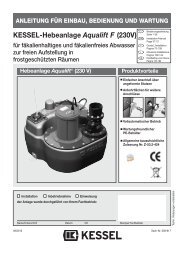
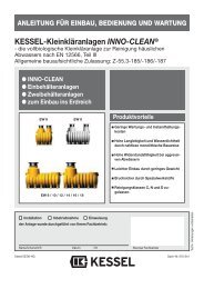
ANLEITUNG FÜR EINBAU, BEDIENUNG UND WARTUNG<br />
<strong>Schaltgerät</strong> <strong>mit</strong> <strong>Drucksensor</strong> <strong>für</strong> <strong>Abwasserstation</strong> Aqualift ® F<br />
Produktvorteile<br />
Bedienungsanleitung<br />
Seite 1-24<br />
Installation Manual<br />
Page 24-48<br />
<strong>Schaltgerät</strong> Spritzwassergeschützt IP 54<br />
Kombinierbar <strong>mit</strong> Abwasserpumpe<br />
Einfachste Montage (inkl. Montageset)<br />
Installation Inbetriebnahme Einweisung<br />
der Anlage wurde durchgeführt von Ihrem Fachbetrieb:<br />
Name/Unterschrift Datum Ort Stempel Fachbetrieb<br />
Änderungsstand: 11/ 2009<br />
Sachnummer: 298-038<br />
Techn. Änderungen vorbehalten
Inhaltsverzeichnis<br />
1. Sicherheitshinweise .......................................................................................................... Seite 4<br />
2. Allgemein .......................................................................................................... Seite 5<br />
3. Montage / Elektroanschluss 3.1 Montage des <strong>Schaltgerät</strong>es ................................................. Seite 6<br />
3.2 Installation............................................................................ Seite 7<br />
3.3 Anschlussplan...................................................................... Seite 8<br />
3.4 Elektroanschluss.................................................................. Seite 9<br />
3.5 Externer Signalgeber ........................................................... Seite 10<br />
3.6 Potentialfreier Kontakt.......................................................... Seite 10<br />
3.7 Kürzen der Steuerleitungen ................................................. Seite 10<br />
3.8 Verlängerung der Steuerleitungen ....................................... Seite 10<br />
3.9 Anschluss Luftschlauch/<strong>Drucksensor</strong> .................................. Seite 10<br />
4. Betrieb 4.1 Inbetriebnahme.................................................................... Seite 12<br />
4.2 Beschreibung der Anzeige- und Bedienelemente................ Seite 12<br />
5. Fehlererkennung .......................................................................................................... Seite 15<br />
6. Zusatzfunktionen 6.1 Automatische Inspektion der Pumpe ................................... Seite 18<br />
6.2 Kontrolle der Batteriespannung ........................................... Seite 18<br />
6.3 Batteriefunktion.................................................................... Seite 18<br />
6.4 Potentialfreier Alarmausgang (Option)................................. Seite 18<br />
6.5 Automatische Wiedereinschaltversuche bei Motorfehler ..... Seite 18
Inhaltsverzeichnis<br />
7. Technische Daten .......................................................................................................... Seite 19<br />
8. Inspektion uns Wartung 8.1 Inspektion............................................................................. Seite 20<br />
8.2 Wartung ............................................................................... Seite 20<br />
8.3 Hinweise zur Pumpe ............................................................ Seite 20<br />
8.4 Hinweise zum elektrischen <strong>Schaltgerät</strong> ............................... Seite 21<br />
8.5 Störungen ............................................................................ Seite 21<br />
9. Gewährleistung .......................................................................................................... Seite 21<br />
10. Übergabeprotokoll .......................................................................................................... Seite 22
1. Sicherheitshinweise<br />
Das Personal <strong>für</strong> Montage, Bedienung,<br />
Wartung und Reparatur muß die entsprechende<br />
Qualifikation <strong>für</strong> diese Arbeiten aufweisen.<br />
Verantwortungsbereich, Zuständigkeit<br />
und die Überwachung des Personals<br />
müssen durch den Betreiber genau geregelt<br />
sein.<br />
Die Betriebssicherheit der gelieferten Anlage<br />
ist nur bei bestimmungsgemäßer Verwendung<br />
gewährleistet. Die Grenzwerte<br />
der technischen Daten dürfen auf keinen<br />
Fall überschritten werden.<br />
Diese Anlage enthält elektrische Spannungen<br />
und steuert mechanische Anlagenteile.<br />
Bei Nichtbeachtung der Einbau und Bedienungsanleitung<br />
können erheblicher Sachschaden,<br />
Körperverletzung oder gar tödliche<br />
Unfälle die Folge sein.<br />
Bei Montage, Bedienung, Wartung und Reparatur<br />
der Anlage sind die Unfallverhütungsvorschriften,<br />
die in Frage kommenden<br />
DIN- und VDE-Normen und Richtlinien sowie<br />
die Vorschriften der örtlichen Energie<br />
Versorgungsunternehmen zu beachten.<br />
Die Anlage stellt eine Komponente einer<br />
Gesamtanlage dar. Beachten Sie deshalb<br />
auch die Bedienungsanleitungen der Gesamtanlage<br />
und der einzelnen Komponenten.<br />
Bei jeder Montage, Wartung, Inspektion<br />
und Reparatur an einer der Komponenten<br />
ist immer die Gesamtanlage außer Betrieb<br />
zu setzen und gegen Wiedereinschalten zu<br />
sichern.<br />
Die Anlage darf nicht in explosionsgefährdeten<br />
Bereichen betrieben werden.<br />
Das <strong>Schaltgerät</strong> steht unter Spannung und<br />
darf nicht geöffnet werden. Nur Elektrofachkräfte<br />
dürfen Arbeiten an elektrischen Einrichtungen<br />
durchführen. Der Begriff Elektrofachkraft<br />
ist in der VDE 0105 definiert.<br />
Es ist sicherzustellen, dass sich die Elektrokabel<br />
sowie alle anderen elektrischen<br />
Anlagenteile in einem einwandfreien Zustand<br />
befinden. Bei Beschädigung darf die<br />
Anlage auf keinen Fall in Betrieb genommen<br />
werden bzw. ist umgehend abzustellen.<br />
Umbau oder Veränderungen der Anlage<br />
sind nur in Absprache <strong>mit</strong> dem Hersteller zu<br />
tätigen. Originalersatzteile und vom Hersteller<br />
zugelassenes Zubehör dienen der<br />
Sicherheit. Die Verwendung anderer Teile<br />
kann die Haftung <strong>für</strong> die daraus entstehenden<br />
Folgen aufheben.<br />
Die Anlage ist über eine Fehlerstrom-<br />
Schutzeinrichtung (RGD) <strong>mit</strong> Bemessungsfehlerstrom<br />
von nicht mehr als 30 mA zu<br />
versorgen.<br />
4
2. Allgemein<br />
Sehr geehrter Kunde,<br />
wir freuen uns, dass Sie sich <strong>für</strong> ein Produkt von KESSEL entschieden haben.<br />
Die gesamte Anlage wurde vor Verlassen des Werkes einer strengen Qualitätskontrolle unterzogen. Prüfen Sie bitte dennoch sofort, ob<br />
die Anlage vollständig und unbeschädigt bei Ihnen angeliefert wurde. Im Falle eines Transportschadens beachten Sie bitte die Anweisung<br />
in Kapitel „Gewährleistung“ dieser Anleitung.<br />
Diese Einbau- und Bedienungsanleitung enthält wichtige Hinweise, die bei Montage, Bedienung, Wartung und Reparatur zu beachten<br />
sind. Vor allen Arbeiten an der Anlage müssen der Betreiber sowie das zuständige Fachpersonal diese Einbau- und Bedienungsanleitung<br />
sorgfältig lesen und befolgen.<br />
Der Einbau und die Installation der <strong>Abwasserstation</strong> in die Bodenplatte wird in der separat <strong>mit</strong>gelieferten Einbauanleitung beschrieben,<br />
d. h. die <strong>Abwasserstation</strong> Aqualift ® F Tronic (Art. Nr. 28 350) besteht aus zwei Einbauanleitungen:<br />
- Anschluss des <strong>Schaltgerät</strong>es<br />
- Einbau des Behälters und Installation der Rohranschlüsse<br />
Verwendungszweck der <strong>Schaltgerät</strong>e:<br />
Das <strong>Schaltgerät</strong> dient der Pumpenansteuerung zum Leeren von Behältern und zum Anzeigen von den Betriebszuständen.<br />
Die Schaltpunkte sind werkseitig voreingestellt.<br />
Zum Feststellen der Schaltpunkte wird ein <strong>Drucksensor</strong> verwendet, der <strong>für</strong> fäkalienhaltiges und -freies Abwasser geeignet ist.<br />
5
3. Montage / Elektroanschluss<br />
3.1 Montage <strong>Schaltgerät</strong><br />
Die Sicherheitshinweise im<br />
Kapitel 1 sind zu beachten!<br />
1<br />
Das <strong>Schaltgerät</strong> wird an geeigneter Stelle,<br />
z.B. in Augenhöhe an der Wand montiert.<br />
Den Gehäusedeckel dazu öffnen. Später <strong>mit</strong><br />
max. 1 Nm wieder verschrauben (selbstschneidende<br />
Schrauben). Den Schaltkasten<br />
wie abgebildet <strong>mit</strong> den 4 Holzschrauben<br />
M3,5x30 an der Wand befestigen. Die Holzschrauben<br />
sowie Kunststoffdübel und eine<br />
Bohrschablone liegen bei.<br />
4<br />
Scharnier (2x)<br />
Kunststoffdübel ( 5x25mm (4x)<br />
Halbrund-Holzschraube M3,5x30 (4x)<br />
Deckelschrauben max 1 Nm (4x)<br />
2<br />
1<br />
3<br />
Schematische Darstellung des <strong>Schaltgerät</strong>es ohne Elektronik-Bauteile.<br />
6
3. Montage / Elektroanschluss<br />
3.2 Installation<br />
Die Anschlussleitungen sind gemäß<br />
Anschlussplan (siehe Kapitel 3) anzuschließen.<br />
Dazu zunächst in den Kabelverschraubungen<br />
die Dichtung <strong>mit</strong> einem Schraubenzieher<br />
durchstoßen (Bild a), die Leitung einführen<br />
(Bild b) und anklemmen (Bild c). Anschließend<br />
kann die Mutter der Kabelverschraubung<br />
<strong>mit</strong> der Hand festgezogen werden<br />
(Bild d).<br />
Beim Anschluss des potentialfreien Kontakts<br />
sind die technischen Daten zu beachten.<br />
Die Dichtungen der Kabelverschraubungen,<br />
die nicht verwendet werden, d.h.<br />
durch die keine Leitung angeschlossen<br />
werden, dürfen nicht durchstoßen werden.<br />
Sie dienen zur Abdichtung des Gehäuses.<br />
WICHTIG:<br />
Alle an dem elektrischen <strong>Schaltgerät</strong> angeschlossenen<br />
Kabel sind bei beendeter<br />
Installation durch geeignete Maßnahmen<br />
(z.B. Kabelbinder) so zu fixieren,<br />
daß sie im 1-Fehler-Fall, also beim Lösen<br />
einer Verbindung, nicht zu einer Gefährdung<br />
führen.<br />
7
3. Montage / Elektroanschluss<br />
3.3 Anschlussplan<br />
<br />
<br />
<br />
<br />
<br />
<br />
<br />
<br />
<br />
<br />
<br />
<br />
<br />
<br />
Hinweis:<br />
Die Vorschriften der VDE 0100, VDE<br />
01107, IEC, bzw. der örtlichen EVU (Energie-Versorgungsunternehmen)<br />
sind<br />
zu beachten.<br />
Das <strong>Schaltgerät</strong> darf nicht in explosionsgefährdeten<br />
Räumen installiert<br />
werden.<br />
Der Netzanschluss ist 230 V AC / 50 Hz<br />
<strong>mit</strong> max. Absicherung 10 A träge vorzusehen<br />
(Fi-Schutzschalter 30 mA).<br />
<br />
<br />
<br />
<br />
<br />
<br />
<br />
<br />
<br />
<br />
<br />
<br />
<br />
<br />
<br />
<br />
<br />
<br />
<br />
<br />
<br />
<br />
<br />
<br />
<br />
<br />
<br />
8
3. Montage / Elektroanschluss<br />
3.4 Elektroanschluss<br />
Die einzelnen Anschlussarbeiten sind in der nachfolgenden Tabelle sowie im Anschlussplan auf der Seite 8, zu beachten sind dabei die jeweiligen<br />
Erläuterungen in Kapitel 3, Elektrisches <strong>Schaltgerät</strong> (Lage der Bedienelemente, Innenansicht des <strong>Schaltgerät</strong>es).<br />
EINZELANLAGE - Sicherheitshinweise beachten !<br />
Auszuführende Arbeit<br />
Netzanschluss<br />
Beschreibung<br />
• Die vorgeschriebene installationsseitige Vorsicherung darf 16A nicht überschreiten.<br />
• Der Netzanschluss <strong>für</strong> die gesamte Anlage ist ein Schutzkontaktstecker <strong>mit</strong>1,7 m Anschlussleitung.<br />
Motorzuleitung<br />
Niveaueingänge<br />
optische Sonde<br />
• Die Motorzuleitung ist entsprechend der Adernummerierung an die entsprechenden Klemmen des<br />
Klemmenblocks „Pumpe“ anzuschließen (Reihenfolge beachten).<br />
Pumpe Ader PE = Klemme PE;<br />
Pumpe Ader 1 = Klemme blau<br />
Pumpe Ader 2 = Klemme schwarz<br />
• Der Schutzleiter ist an der Klemme PE des Klemmenblocks „Pumpe“ anzuschließen<br />
• Die Sondenleitung ist entsprechend der Adernummerierung an die Klemmen des Klemmblocks<br />
„Sonde“ anzuschließen.<br />
Die Reihenfolge beachten.<br />
Sonde Ader 1 (-) = Klemme blau<br />
Sonde Ader 2 = Klemme weiß<br />
Sonde Ader 3 (+) = Klemme schwarz<br />
Nach dem vollständigen Elektroanschluss ist der Deckel des <strong>Schaltgerät</strong>es wieder ordnungsgemäß <strong>mit</strong> den 4 Schrauben zu verschließen.<br />
9
3. Montage / Elektroanschluss<br />
3.5 Externer Signalgeber<br />
Der externe Signalgeber (Best.Nr. 20162)<br />
zur Übertragung des Warntons in andere<br />
Räume kann nach Bedarf angeschlossen<br />
werden.<br />
3.6 Potentialfreier Kontakt (Abb. 1-3)<br />
Optional kann eine Zusatzplatine <strong>mit</strong> einem potentialfreien<br />
Kontakt (Best.Nr. 80072), z. B. zum<br />
Anschluß des <strong>Schaltgerät</strong>es an die zentrale<br />
Leittechnik des Gebäudes, angeschlossen werden.<br />
Die Zusatzplatine <strong>mit</strong>tels vierAbstandshalter<br />
auf die Basisplatine aufstecken.<br />
Anschließend den Platinenanschluß auf die Basisplatine<br />
oben aufstecken. Jeder Alarm, außer<br />
bei Klappenführung, wird bei Rückstau oder<br />
einer Störung über den potentialfreien Kontakt<br />
gemeldet. Bei Klappenprüfung (Tastenfunktion<br />
1. 2. 3.<br />
“Klappe Test” erfolgt keine Alarmmeldung über<br />
den potentialfreien Kontakt.<br />
3.7 Kürzen der Steuerleitungen<br />
Die Steuerleitungen können bei Bedarf<br />
auch gekürzt werden. Bei den Aderendhülsen<br />
ist zu beachten, dass die Anschlußklemmen<br />
<strong>für</strong> einen max. Querschnitt<br />
von 2,5 mm 2 ausgelegt sind. Dieser Querschnitt<br />
darf nicht überschritten werden.<br />
3.8 Verlängerung der Steuerleitung<br />
Die Verlängerung der Steuerleitung nur<br />
nach Rücksprache <strong>mit</strong> Werk.<br />
3.9 Anschluss Luftschlauch / <strong>Drucksensor</strong><br />
(Abb. 5-6)<br />
Den Schlauch stetig steigend verlegen,<br />
nicht knicken oder rollen.<br />
Den Schlauch des <strong>Drucksensor</strong>s in die Verschraubung<br />
am <strong>Schaltgerät</strong> stecken und<br />
die Überwurfmutter verschrauben. Gegebenenfalls<br />
ist er zu kürzen.<br />
Nicht aufgerollt/geknickt einbauen<br />
Zulässige<br />
Luftschlauchverlegung<br />
im<br />
Behälter.<br />
5. 6.<br />
10
4. Betrieb<br />
a<br />
b<br />
d<br />
e<br />
f<br />
i<br />
j<br />
g<br />
h<br />
a) Gehäuse <strong>Schaltgerät</strong><br />
b) Zylinderschraube M 4x28 (4x)<br />
c) Netzanschlussleitung<br />
d) Kurzbedienungsanleitung<br />
e) grüne LED „Netz“<br />
f) rote LED „Alarm“<br />
g) orange LED „Niveau“<br />
h) orange LED „Pumpe“<br />
i) Taste „Alarm“<br />
j) Taste „Pumpe“<br />
k) Anschluss Pumpenmotor<br />
l) Anschluss <strong>Drucksensor</strong><br />
m) Anschluss potentialfreier Kontakt<br />
n) Anschluss optische Sonde<br />
o) Anschluss externer Signalgeber<br />
c k l o m n<br />
11
4. Betrieb<br />
4.1 Inbetriebnahme<br />
Die im Lieferumfang enthaltenen Batterien<br />
(2x) anstecken, den Gehäusedeckel schließen<br />
und wieder verschrauben. Vor der Inbetriebnahme<br />
muss die Pumpe, der <strong>Drucksensor</strong><br />
und die optische Sonde fest eingebaut und<br />
angeschlossen sein. Der <strong>Schaltgerät</strong>edeckel<br />
muss verschlossen sein. Danach die Netzleitung<br />
anschließen.<br />
Das <strong>Schaltgerät</strong> führt einen Grundfunktionstest,<br />
die sog. Initialisierung durch. Dies wird<br />
durch ein Lauflicht ca. 8 sec. nach Anstecken<br />
der Batterie, bzw. des Netzsteckers angezeigt.<br />
Bei der Initialisierung werden Batterie-, Netz-,<br />
<strong>Drucksensor</strong>- und Motoranschluss überprüft.<br />
Bei korrektem Anschluss des <strong>Schaltgerät</strong>es<br />
leuchtet anschließend die Power-LED (grün).<br />
Die <strong>Abwasserstation</strong> Aqualift ® F ist jetzt betriebsbereit.<br />
4.2 Beschreibung der Anzeige- und Bedienelemente<br />
Anzeigeelemente LED Farbe Funktion<br />
Normalbetrieb „Power“ grün Spannungsversorgung in Ordnung<br />
(zur Information „Alarm“ rot Alarm-Niveau überschritten<br />
<strong>für</strong> den Bediener) „Niveau“ orange Ein-Niveau überschritten<br />
„Pumpe“ orange Pumpenausgang aktiviert<br />
Störungen<br />
siehe Abschnitt 5, Anzeige von Warnungen und Fehlern<br />
Bedienelemente<br />
Taste „Alarm“ Ausschalten des akustischen Alarms,<br />
Quittieren von Warnungen und Fehlern,<br />
Anwählen und Verändern von Einstellungen<br />
„Pumpe“<br />
Handbetrieb Pumpe,<br />
Anwählen und Abspeichern von neuen Einstellungen<br />
12
4. Betrieb<br />
Funktion des <strong>Schaltgerät</strong>s<br />
A) Normalbetrieb:<br />
Die Niveaumessung erfolgt über zwei von<br />
einander unabhängige Verfahren. Das<br />
AUS-Niveau und das EIN-Niveau werden<br />
über einen <strong>Drucksensor</strong> gemessen. Das<br />
ALARM-Niveau wird über eine optische<br />
Sonde gemessen.<br />
Wenn ein Messverfahren ausfällt, bleibt die<br />
Anlage trotzdem über das andere Messverfahren<br />
funktionsfähig.<br />
Am <strong>Schaltgerät</strong> wird der Sondenfehler bzw.<br />
Niveaufehler optisch und akustisch angezeigt.<br />
1) <strong>Drucksensor</strong> und optische Sonde funktionsfähig<br />
Die Anlage wird über das AUS-Niveau, EIN-<br />
Niveau und ggf. ALARM-Niveau geschaltet.<br />
Die grüne LED „POWER“ leuchtet.<br />
Wenn <strong>mit</strong> steigendem Niveau im Behälter<br />
das EIN-Niveau überschritten wird, startet<br />
die Einschaltverzögerungszeit von 2 Sekunden.<br />
Die Pumpe wird eingeschaltet und<br />
läuft an einem Stück bis das AUS-Niveau<br />
wieder unterschritten wird.<br />
Wahrend des Pumpenlaufs leuchten die<br />
orange LED „NIVEAU“ und die orange LED<br />
„PUMPE“.<br />
Wenn das Alarm-Niveau überschritten wird,<br />
startet die Einschaltverzögerungszeit von 2<br />
Sekunden. Die rote LED „ALARM“ leuchtet<br />
und der akustische Alarm ertönt. Die Pumpe<br />
wird spätestens jetzt eingeschaltet.<br />
Wenn das Alarm-Niveau wieder unterschritten<br />
wird, erlischt der akustische Alarm und<br />
die rote LED „ALARM“ blinkt.<br />
Die blinkende LED „ALARM“ zeigt an, dass<br />
das Alarm-Niveau, wenn auch nur kurzzeitig,<br />
überschritten war.<br />
Die Pumpe läuft an einem Stück bis das<br />
AUS-Niveau wieder unterschritten wird.<br />
Wahrend des Pumpenlaufs leuchten die<br />
orange LED „NIVEAU“ und die orange LED<br />
„PUMPE“.<br />
2) <strong>Drucksensor</strong> nicht funktionsfähig und optische<br />
Sonde funktionsfähig<br />
Die Anlage wird nur über das Alarm-Niveau<br />
geschaltet<br />
Die grüne LED „POWER“ leuchtet.<br />
Wenn <strong>mit</strong> steigendem Niveau im Behälter<br />
das ALARM-Niveau überschritten wird,<br />
startet die Einschaltverzögerungszeit von 2<br />
Sekunden. Die rote LED „ALARM“ leuchtet<br />
und der akustische Alarm ertönt. Die Pumpe<br />
wird eingeschaltet. Wenn das ALARM-Niveau<br />
wieder unterschritten wird, erlischt der<br />
akustische Alarm und die rote LED<br />
„ALARM“ blinkt. Die Pumpe läuft noch 5 Sekunden<br />
nach. Während des Pumpenlaufs<br />
leuchtet die orange LED „PUMPE“. Die<br />
orange LED „NIVEAU“ leuchtet nicht, weil<br />
das AUS-Niveau und / oder EIN-Niveau<br />
nicht erkannt wurden.<br />
13
4. Betrieb<br />
Die blinkende LED ALARM zeigt an, dass<br />
das ALARM-Niveau, wenn auch nur kurzzeitig,<br />
überschritten war - hier wegen Niveaufehler.<br />
3) <strong>Drucksensor</strong> funktionsfähig und optische<br />
Sonde nicht funktionsfähig<br />
Die Anlage wird nur über das AUS-Niveau<br />
und EIN-Niveau geschaltet.<br />
Das ALARM-Niveau kann nicht gemessen<br />
werden.<br />
Die beiden oberen LEDʼs blinken abwechselnd<br />
<strong>mit</strong> den unteren LEDʼs (= Sondenfehler).<br />
Wenn <strong>mit</strong> steigendem Niveau im Behälter<br />
das EIN-Niveau überschritten wird, startet<br />
die Einschaltverzögerungszeit von 2 Sekunden.<br />
Die optische Anzeige wechselt.<br />
Die grüne LED „POWER“ leuchtet, die rote<br />
LED „ALARM“ blinkt, die orange LED „NI-<br />
VEAU“ und die orange LED „PUMPE“<br />
leuchten.<br />
Die Pumpe wird eingeschaltet und läuft ununterbrochen<br />
bis das AUS-Niveau wieder<br />
unterschritten wird.<br />
Die optische Anzeige wechselt wieder<br />
zurück zu Sondenfehler.<br />
Die beiden oberen LEDʼs blinken abwechselnd<br />
<strong>mit</strong> den unteren LEDʼs (= Sondenfehler).<br />
B) Handbetrieb:<br />
Wenn die Anlage im Normalbetrieb ist, kann<br />
durch Drücken der Taste „PUMPE“ der<br />
Motor von Hand eingeschalten werden. Die<br />
Pumpe läuft solange wie die Taste gedrückt<br />
wird, mindestens aber <strong>für</strong> 2 Sekunden,<br />
wenn die Taste nur kurz gedrückt wurde.<br />
Während des Pumpenlaufes blinkt die orange<br />
LED „PUMPE“.<br />
14
5. Fehlererkennung<br />
Mit dem KESSEL-<strong>Schaltgerät</strong> können Fehler bei der Inbetriebnahme sowie während des Betriebs erkannt und so<strong>mit</strong> leicht abgestellt werden.<br />
Störungen bei Netzbetrieb:<br />
Fehler Ursache Abstellmaßnahme Hinweise<br />
Power-LED blinkt abwechselnd,<br />
<strong>mit</strong><br />
Alarm-LED, Alarm<br />
Batterie fehlt oder ist defekt<br />
Batterien anschließen, ggf. durch neue<br />
Batterien ersetzen<br />
Die Funktionsbereitschaft des Gerätes<br />
wird durch ein erneutes Lauflicht angezeigt.<br />
- Initialisierung: Die Anlage kann in Betrieb genommen<br />
werden, d. h. sie ist funktionsfähig.<br />
- Betrieb: Die Fehlermeldung wird spätestens<br />
nach 5 Min. angezeigt. Die Anlage ist funktionsbereit;<br />
Handbetrieb ist möglich. Das Austauschen /<br />
Anschließen der Batterien wird nach spätestens 5<br />
Min. durch die leuchtende Netz-LED angezeigt.<br />
Alle LEDʼs blinken<br />
gleichzeitig, Alarm<br />
- Initialisierung:<br />
„Pumpe“ nicht angeschlossen,<br />
verpolt oder gebrochen<br />
- Im Betrieb:<br />
„Pumpe“ defekt oder<br />
“Pumpe” überhitzt, Motorschutz<br />
schaltet Pumpe ab.<br />
Netzstecker ziehen, Batterie abklemmen;<br />
Steuerleitung auf korrekten Anschluss,<br />
bzw. Durchgang kontrollieren,<br />
ggf. Motor austauschen.<br />
Bei Überhitzung Zulauf begrenzen;<br />
ggf. Sonden/ Schwimmer reinigen<br />
Fehlererkennung erfolgt nur im Betrieb (siehe<br />
dazu Kap. 6 „Zusatzfunktionen“).<br />
Pumpe schaltet nach Abkühlung (ca 10 min.)<br />
automatisch wieder ein, wenn Niveau vorliegt.<br />
Die oberen und unteren<br />
LEDʼs blinken<br />
abwechselnd, Alarm<br />
- Initialisierung:<br />
„Sonde“ nicht angeschlossen,<br />
verpolt oder gebrochen<br />
- Im Betrieb:<br />
„Sonde“ defekt<br />
Netzstecker ziehen, Batterie abklemmen;<br />
Steuerleitung auf korrekten Anschluss,<br />
bzw. Durchgang kontrollieren;<br />
ggf. Sonde austauschen.<br />
- Die Abfrage der Sonde erfolgt alle 2 sec.<br />
- Pumpe kann von Hand betätigt werden<br />
- Wenn das Ein-Niveau überschritten ist, wird die<br />
Pumpe automatisch ausgeschalten.<br />
- Wenn die Pumpe ausgeschaltet ist, wechselt die optische<br />
Anzeige wieder zu Sondenfehler.<br />
15
5. Fehlererkennung<br />
Störungen bei Netzbetrieb:<br />
Fehler Ursache Abstellmaßnahme Hinweise<br />
Alarm-LED blinkt<br />
- Alarm Niveau überschritten<br />
- Niveaufehler/Sensorfehler<br />
- Grenzlaufzeit<br />
Zulaufmenge prüfen<br />
Pumpe prüfen<br />
<strong>Drucksensor</strong> prüfen<br />
Sonde reinigen<br />
- Alarm Niveau war kurzzeitig überschritten<br />
- <strong>Drucksensor</strong> defekt; es wird <strong>mit</strong> der optischen<br />
Sonde geschaltet<br />
- Die Pumpe ist mehr als 3 Minuten an einem<br />
Stück gelaufen oder hat mehr als 20 Schaltspiele<br />
in 3 Minuten<br />
- Bei übermäßiger Schaumbildung die Dosierung<br />
(Waschmaschine, Dusche) reduzieren<br />
- Wasserenthärtungsanlagen führen zu weicherem<br />
Wasser und ggf. zu höherer<br />
Schaumbildung<br />
Alle LEDs leuchten<br />
akkustischer Alarm<br />
nicht ausschaltbar<br />
Relaisfehler<br />
(Relaiskontakt verschweißt)<br />
Netzstecker ziehen,<br />
Anlage außer Betrieb nehmen<br />
Das <strong>Schaltgerät</strong> ist nicht mehr funktionsfähig<br />
Lauflicht der LEDs<br />
von oben nach<br />
unten und von<br />
unten nach oben<br />
Kommunikationsfehler oder<br />
Verbindungsstecker zwischen<br />
beiden Platinen entfernt<br />
Verbindung wieder herstellen<br />
Zwischen beiden Platinen findet kein Datenaustausch<br />
statt.<br />
16
5. Fehlererkennung<br />
Netzausfall:<br />
Fehler Ursache Abstellmaßnahme Hinweise<br />
Alarm-LED blinkt<br />
im 2-sec.-Takt;<br />
Alle anderen LEDʼs<br />
sind aus<br />
Netzspannung fehlt<br />
Netzspannung kontrollieren, ggf.<br />
wiederherstellen<br />
Die Pumpe kann ohne Netzspannung<br />
kein Abwasser entsorgen! Die Alarmmeldung<br />
bleibt aktiv.<br />
Alarm-LED und Niveau-LED<br />
blinken<br />
im 2-Takt, Alarm<br />
Netzspannung fehlt und Niveau<br />
vorhanden<br />
Netzspannung kontrollieren, ggf.<br />
wiederherstellen<br />
Die Pumpe kann ohne Netzspannung<br />
kein Abwasser entsorgen! Die Alarmmeldung<br />
bleibt aktiv.<br />
Alle LEDʼs sind aus Netzspannung fehlt oder<br />
Batterien defekt/nicht vorhanden<br />
Netzspannung kontrollieren, ggf.<br />
wiederherstellen<br />
Gerät ist nicht betriebsfähig<br />
17
6. Zusatzfunktionen<br />
6.1 Automatische Inspektion der Pumpe<br />
Einmal wöchentlich wird die Pumpe automatisch<br />
auf ihre Funktion überprüft. Dazu<br />
wird die Pumpe automatisch <strong>für</strong> 2 sec. angesteuert.<br />
Erkannte Fehler werden <strong>mit</strong> der entsprechenden<br />
Meldung angezeigt und können<br />
dann wie im Kap. 6 beschrieben, beseitigt<br />
werden.<br />
6.2 Kontrolle der Batteriespannung<br />
Die Steuerung überprüft konstant die Batteriespannung.<br />
Liegt diese bei Einbau bereits<br />
unter 12,5 V, läßt sich die <strong>Abwasserstation</strong><br />
Aqualift ® -F trotzdem in Betrieb nehmen.<br />
Bitte überprüfen Sie in beiden Fällen die<br />
Batterien und tauschen diese ggf. gegen<br />
Neue aus. Dazu trennen Sie zunächst das<br />
<strong>Schaltgerät</strong> vom Netz. Nach Öffnen des<br />
<strong>Schaltgerät</strong>edeckels sind beide Batterie-<br />
Anschlussleitungen von den Batterien abzustecken,<br />
die Batterien auszutauschen<br />
und die neuen Batterien wieder anzuschließen.<br />
Danach ist der Deckel wieder<br />
zu schließen und der Netzstecker einzustecken.<br />
Die gebrauchten Batterien sind<br />
fachgerecht zu entsorgen!<br />
6.3 Batteriefunktion<br />
Die Batterien melden den Netzausfall akustisch<br />
und optisch. Die Pumpe kann nicht<br />
<strong>mit</strong> den Batterien (d.h. bei Netzausfall) betrieben<br />
werden. Ohne Batterien oder defekten<br />
Batterien haben Sie keine Meldung<br />
über einen Netzausfall.<br />
Achtung: Bei Verschrottung des <strong>Schaltgerät</strong>es<br />
sind die Batterien ebenfalls zu<br />
entnehmen und entsprechend fachgerecht<br />
zu entsorgen!<br />
Für die KESSEL<strong>Abwasserstation</strong> Aqualift ® -<br />
F ist folgende Batterie zugelassen: Duracell:<br />
Size 9V; Typ MN 1604/6LR61 (Bedarf:<br />
2 Stück)<br />
6.4 Potentialfreier Alarmausgang (Option)<br />
Das KESSEL-<strong>Schaltgerät</strong> <strong>für</strong> die <strong>Abwasserstation</strong><br />
Aqualift ® -F kann <strong>mit</strong> einem Anschluss<br />
<strong>für</strong> einen potentialfreien Kontakt<br />
aus-, bzw. nachgerüstet werden.<br />
Dazu wird nur die Zusatzplatine (Best.Nr.<br />
80072) im <strong>Schaltgerät</strong> angesteckt (siehe<br />
kapitel 3.4) und die gewünschte Steuerleitung<br />
an die Anschlussklemmen angeschlossen.<br />
Das Relais fällt bei Fehlermeldungen<br />
und Netzausfall ab.<br />
Achtung: Der potentialfreie Anschluss<br />
ist nur bis 42 V DC / 0,5 A zugelassen.<br />
6.5 Automatische Wiedereinschaltversuche<br />
bei Motorfehler<br />
Bei einem Motorfehler, z.B. der interne<br />
Wicklungstemperaturschalter hat abgeschaltet,<br />
versucht das <strong>Schaltgerät</strong> im Abstnad<br />
von 2 Minuten bis zu 30mal die Pumpe<br />
wieder <strong>für</strong> 2 Sekunden einzuschalten.<br />
Wenn der automatische Wiedereinschaltversuch<br />
erfolgreich ist, quittiert sich der Motorfehler<br />
selbsttätig. Wenn die automatischen<br />
Wiedereinschaltversuche erfolglos<br />
waren, wird der Motorfehler weiterhin angezeigt.<br />
18
7. Technische Daten<br />
<strong>Schaltgerät</strong><br />
Netzanschluss<br />
Absicherung 10 A träge; FI Schutzschalter 30 mA<br />
Netzspannung / Netzfrequenz<br />
230 V AC / 50 Hz<br />
Netzstrom Standby (Einsatzbereit)<br />
18 mA<br />
Netzstrom in Betrieb<br />
5,3 A<br />
Einsatztemperatur 0°C bis + 40°C<br />
Schutzart<br />
IP 54 (<strong>Schaltgerät</strong>)<br />
Schutzklasse 1<br />
Schaltleistung 230 V AC, 16 A, cos φ = 1<br />
Schaltleistung des potentialfreien Kontaktes (Option)<br />
42 V DC / 0,5 A<br />
Motor/Sonde<br />
Aufnahmeleistung (P1)<br />
1,2kW<br />
Nennstrom<br />
5,3 A<br />
Betriebsart S3 - 30%<br />
Schutzart<br />
IP 68 bei max. 3 m/24 h<br />
Steuerleitung Motor 3x1 mm 2<br />
Steuerleitung Sonde 3x0,75 mm 2<br />
19
8. Inspektion und Wartung<br />
8.1 Inspektion<br />
Die Anlage ist monatlich vom Betreiber<br />
durch Beobachtung eines Schaltspiels auf<br />
Betriebsfähigkeit und Dichtheit zu überprüfen:<br />
• Abwasserzulauf sicherstellen<br />
• Anschalten Niveau-Signal und Pumpe abwarten<br />
• Abwasserzulauf abstellen<br />
• Ausschalten Niveau-Signal und Pumpe<br />
abwarten<br />
8.2 Wartung<br />
ACHTUNG:<br />
Bei allen Wartungsarbeiten, Anlage vom<br />
Netz trennen! Sicherheitshinweise beachten!<br />
Alle nachfolgend beschriebenen<br />
Inspektions- und Wartungsarbeiten dürfen<br />
nur von autorisiertem Fachpersonal<br />
durchgeführt werden. Reparaturen dürfen<br />
nur durch den Hersteller vorgenommen<br />
werden.<br />
Wartungsarbeiten sind regelmäßig von autorisiertem<br />
Fachpersonal durchzuführen.<br />
Dabei sind folgende Tätigkeiten durchzuführen:<br />
• Sichtprüfung der Gesamtanlage<br />
• Gründliche Reinigung der Gesamtanlage<br />
und der Pumpe<br />
• Überprüfen von Gesamtanlage und Pumpengehäuse<br />
auf äußere Mängel und sichtbaren<br />
Verschleiß<br />
• Prüfung der Pumpe auf Leichtgängigkeit,<br />
Verschleiß und Ablagerungen<br />
• Kontrolle der Anschlussleitungen auf mechanische<br />
Beschädigungen und Verschleiß<br />
• Kontrolle der Dichtungsverbindungen auf<br />
Dichtheit und erkennbaren Verschleiß<br />
• Isolationsprüfung des Pumpenmotors<br />
• Kontrolle der elektrischen Anschlussleitungen,<br />
sowie des Staurohrs und des Luftschlauches<br />
auf mechanische Beschädigungen<br />
und Verschleiß, z.B. Risse,<br />
Knicke, Verschmutzungen, Ablagerungen.<br />
Dazu den Luftschlauch vom <strong>Schaltgerät</strong><br />
abschrauben, das Staurohr herausnehmen,<br />
reinigen und durchblasen. Anschließend<br />
zuerst den Luftschlauch am<br />
<strong>Schaltgerät</strong> wieder anschließen und danach<br />
das Staurohr wieder einsetzten.<br />
Bitte halten Sie diese Reihenfolge<br />
unbedingt ein, da<strong>mit</strong> die Funktion gewährleistet<br />
ist.<br />
Diese Arbeiten empfehlen wir auch nach<br />
längerem Stillstand oder Zwischenlagerung.<br />
8.3 Hinweise zur Pumpe<br />
Die Pumpe sollte in regelmäßigen Abständen<br />
kontrolliert werden. Bei zunehmenden<br />
Betriebsgeräuschen, abnehmender Förderleistung<br />
oder Schwingungen im Rohrleitungssystem<br />
müssen Pumpengehäuse und<br />
Laufrad auf festsitzende Verunreinigungen<br />
oder Verschleiß überprüft werden.<br />
20
8. Inspektion und Wartung<br />
1. Ist eine Lieferung oder Leistung mangelhaft,<br />
so hat KESSEL nach Ihrer Wahl den<br />
Mangel durch Nachbesserung zu beseitigen<br />
oder eine mangelfreie Sache zu liefern.<br />
Schlägt die Nachbesserung zweimal fehl oder<br />
ist sie wirtschaftlich nicht vertretbar, so hat der<br />
Käufer/Auftraggeber das Recht, vom Vertrag<br />
zurückzutreten oder seine Zahlungspflicht<br />
entsprechend zu mindern. Die Feststellung<br />
von offensichtlichen Mängeln muss unverzüglich,<br />
bei nicht erkennbaren oder verdeckten<br />
Mängeln unverzüglich nach ihrer Erkennbarkeit<br />
schriftlich <strong>mit</strong>geteilt werden. Für Nachbesserungen<br />
und Nachlieferungen haftet<br />
8.4 Hinweise zum elektrischen<br />
<strong>Schaltgerät</strong><br />
• Die Batterien sind Verschleißteile und sollten<br />
möglichst jährlich überprüft und gegebenenfalls<br />
gewechselt werden. Beim<br />
Wechseln ist auf umweltgerechte Entsorgung<br />
zu achten. Ersatz darf nur durch gleichen<br />
Typ erfolgen.<br />
• Reparaturen dürfen nur durch den Hersteller<br />
vorgenommen werden.<br />
8.5 Störungen<br />
Sollten nicht behebbare Störungen auftreten,<br />
wenden Sie sich bitte im Zweifelsfall an<br />
9. Gewährleistung<br />
KESSEL in gleichem Umfang wie <strong>für</strong> den ursprünglichen<br />
Vertragsgegenstand. Für Neulieferungen<br />
beginnt die Gewährleistungsfrist<br />
neu zu laufen, jedoch nur im Umfang der Neulieferung.<br />
Es wird nur <strong>für</strong> neu hergestellte Sachen eine<br />
Gewährleistung übernommen.<br />
Die Gewährleistungsfrist beträgt 24 Monate<br />
ab Auslieferung an unseren Vertragspartner.<br />
§§ 377.378 HGB finden weiterhin Anwendung.<br />
Über die gesetzliche Regelung hinaus erhöht<br />
KESSEL die Gewährleistungsfrist <strong>für</strong> Leichtflüssigkeitsabscheider,<br />
Fettabscheider,<br />
Schächte, Kleinkläranlagen und Regenwas-<br />
Ihren Fachbetrieb (siehe Stempel auf Deckblatt),<br />
der auch die Installation durchgeführt<br />
hat.<br />
Unsere Kundendienstpartner finden Sie<br />
unter:<br />
www.kessel.de/ewt/kontakt/kundendienst<br />
serzisternen auf 20 Jahre bezüglich Behälter.<br />
Dies bezieht sich auf die Dichtheit, Gebrauchstauglichkeit<br />
und statische Sicherheit.<br />
Voraussetzung hier<strong>für</strong> ist eine fachmännische<br />
Montage sowie ein bestimmungsgemäßer Betrieb<br />
entsprechend den aktuell gültigen Einbau-<br />
und Bedienungsleitungen und den gültigen<br />
Normen.<br />
2. KESSEL stellt ausdrücklich klar, dass Verschleiß<br />
kein Mangel ist. Gleiches gilt <strong>für</strong> Fehler,<br />
die aufgrund mangelhafter Wartung auftreten.<br />
Stand 10.11.2009<br />
21
10. Übergabeprotokoll<br />
Typenbezeichnung *<br />
KESSEL-Bestellnummer *<br />
Fertigungsdatum *<br />
(* gemäß Typenschild/Rechnung)<br />
Objektbezeichung / Anlagenbetreiber<br />
Adresse / Telefon / Telefax<br />
Planer<br />
Adresse / Telefon / Telefax<br />
Ausführende Installationsfirma<br />
Adresse / Telefon / Telefax<br />
Abnahmeberechtigter<br />
Adresse / Telefon / Telefax<br />
Übergabeperson<br />
Sonstige Anmerkungen<br />
Die aufgeführte Inbetriebnahme und Einweisung wurde im Beisein des Abnahmeberechtigten und des Anlagenbetreibers durchgeführt.<br />
______________________________ ______________________________ _________________________<br />
Ort, Datum Unterschrift Abnahmeberechtigter Unterschrift Anlagenbetreiber<br />
22
Übergabeprotokoll<br />
■<br />
■<br />
■<br />
✂<br />
23
EG - KONFORMITÄTSERKLÄRUNG<br />
EMV-Richtlinie 89/336/EWG<br />
Niederspannungsrichtlinie 73/23/EWG<br />
Maschinenrichtlinie 98/37/EG<br />
Der Hersteller<br />
<strong>Kessel</strong>, D-85101 Lenting<br />
erklärt, dass das Produkt<br />
<strong>Kessel</strong>-<strong>Abwasserstation</strong> zum Einbau in die Bodenplatte<br />
enwickelt und gefertigt worden ist<br />
in Übereinstimmung <strong>mit</strong> folgenden Normen:<br />
EN 12100-2 (2003-11)<br />
EN 12100-1 (2003-11)<br />
EN 60335-1 (2003-5)<br />
EN 60335-2 (1996-09)<br />
EN 61000-6-1 (2002-1)<br />
EN 61000-6-4 (2002-01)<br />
EN 809 (1998-11)<br />
EN 60730-1<br />
Sicherheit von Maschinen<br />
Sicherheit von Maschinen<br />
Sicherheit elektrischer Geräte <strong>für</strong> den Hausgebrauch<br />
Sicherheit elektrischer Geräte <strong>für</strong> den Hausgebrauch<br />
Elektromagnetische Verträglichkeit (EMV)<br />
Elektromagnetische Verträglichkeit (EMV)<br />
Pumpen und Pumpengeräte <strong>für</strong> Flüssigkeiten<br />
Automatische elektrische Regel- und Steuergeräte <strong>für</strong> den Hausgebrauch<br />
Lenting, den 07.03.2007<br />
B. <strong>Kessel</strong> A. <strong>Kessel</strong><br />
24
INSTRUCTIONS FOR INSTALLATION, OPERATION AND MAINTENANCE<br />
Switch unit with pressure sensor<br />
for the wastewater station Aqualift ® F<br />
Product advantages<br />
Switch unit splashwater-proof IP 54<br />
Can be combined with wastewater pump<br />
Extremely easy installation (inc. installation set)<br />
Installation Service<br />
of this unit should be carried out by a licensed professsional<br />
servicer:<br />
Company / Telephone number<br />
Edition: 11/ 2009<br />
Numberr: 298-038<br />
Subject to technical amendments
Table of contents<br />
1. Safety Instructions .......................................................................................................... page 28<br />
2. General .......................................................................................................... page 29<br />
3. Installation 3.1 Installation of the switch unit ................................................ page 30<br />
3.2 Installation............................................................................ page 31<br />
3.3 Connection diagram............................................................. page 32<br />
3.4 Electrical connection ............................................................ page 33<br />
3.5 External signal generator ..................................................... page 34<br />
3.6 Potential-free switch contact ................................................ page 34<br />
3.7 Shortening the control cables .............................................. page 35<br />
3.8 Extending the control cables................................................ page 35<br />
3.9 Connection air hose/pressure sensor .................................. page 35<br />
4. Operation 4.1 Initial operation..................................................................... page 36<br />
4.2 Description of the display and control element .................... page 36<br />
5. Errors and Malfunction .......................................................................................................... page 39<br />
6. Additional functions 6.1 Automatic pump inspection.................................................. page 42<br />
6.2 Checking the battery voltage ............................................... page 42<br />
6.3 Battery function .................................................................... page 42<br />
6.4 Potential-free alarm output (option) ..................................... page 42<br />
6.5 Automatic restart attempts in the event of a motor fault....... page 42<br />
26
Table of contents<br />
7. Technical Data .......................................................................................................... page 43<br />
8. Inspection and maintenance 8.1 Inspection............................................................................. page 44<br />
8.2 Maintenance ........................................................................ page 44<br />
8.3 Notes on the pump............................................................... page 45<br />
8.4 Notes on the electrical switch unit........................................ page 45<br />
8.5 Problems.............................................................................. Seite 45<br />
9. Guarantee .......................................................................................................... page 46<br />
10. Handover Certificate .......................................................................................................... page 47<br />
27
1. Safety instructions<br />
The personnel for assembly, operation,<br />
maintenance and repair must possess the<br />
appropriate qualification for this type of<br />
work. The area of responsibility, the authority<br />
and the supervision of personnel must<br />
be exactly regulated by the operator.<br />
The operational safety of the system supplied<br />
is only guaranteed when it is used in<br />
accordance with the regulations. The li<strong>mit</strong>s<br />
of the technical specifications may not be<br />
exceeded on any account.<br />
This system contains electric charges and<br />
controls mechanical plant components.<br />
Non-compliance with the installation and<br />
operating instructions may result in considerable<br />
damage to property, personal injuries<br />
or even fatal accidents.<br />
During assembly, operation, maintenance<br />
and repair of the system, the regulations<br />
for the prevention of accidents, the pertinent<br />
DIN and VDE standards and directives,<br />
as well as the directives of the local<br />
power supply industry must be heeded.<br />
The system represents one component in<br />
a whole station. Please therefore also<br />
heed the operating instructions for the station<br />
as a whole and the individual components.<br />
During assembly, maintenance, service<br />
and repair work on one of the components,<br />
the station as a whole must always<br />
be put out of operation and secured<br />
against unintentional restart.<br />
The system must not be operated in potentially<br />
explosive areas.<br />
The switch unit is live and must not be<br />
opened. Only qualified electricians may<br />
carry out work on electrical facilities. The<br />
term qualified electrician is defined in VDE<br />
0105.<br />
It must be ensured that the electric cables<br />
as well as all other electrical system components<br />
are in a faultless condition. In<br />
case of damage, the system may on no<br />
account be put into operation or must be<br />
stopped immediately.<br />
Conversions or changes to the system<br />
may only be carried out in agreement with<br />
the manufacturer. For safety reasons, use<br />
original spare parts and accessories approved<br />
by the manufacturer. The use of<br />
other parts may void the liability for any<br />
consequences arising thereof.<br />
The unit must be supplied through a residual-current-operated<br />
protected device<br />
(RCD) with residual current of not more<br />
than 30 mA.<br />
28
2. General<br />
Dear customer,<br />
we are pleased that you have decided to buy a KESSEL product.<br />
The entire system was subjected to a stringent quality control before it left our factory. Nevertheless, please check immediately whether<br />
the system has been delivered to you complete and undamaged. In case of any transport damage, please refer to the instructions in the<br />
chapter “Warranty” in this manual.<br />
These installation, operating and maintenance instructions contain important information that has to be observed during assembly, operation,<br />
maintenance and repair. Prior to carrying out any work on the system, the operator and the responsible technical personnel must<br />
carefully read and heed these installation and operating instructions.<br />
The installation of the wastewater station in the ground plate is described in the separate instructions, i.e. the wastewater station <strong>Aqualift®</strong><br />
F Tronic (art. no. 28350) has two sets of installation instructions:<br />
- Connection of the switch unit<br />
- Installation of the tank and pipe connections<br />
Purpose of the switch units:<br />
The switch unit triggers the pump to empty tanks and indicates operational states.<br />
Default settings for the switching points are made in the factory.<br />
A pressure sensor that is suitable for wastewater both with and without sewage is used for determining the switching points.<br />
29
3. Installation<br />
3.1 Installation of the switch unit<br />
The safety instructions in chapter 1 must<br />
be heeded!<br />
1<br />
The switch unit is installed in a suitable spot,<br />
e.g. at eye level on the wall. To do this, open<br />
the housing cover. Screw in place (self-cutting<br />
screws) later using max. 1 Nm. Attach<br />
the switch box to the wall as shown using the<br />
4 wood screws M3.5x30. The wood screws,<br />
plastic dowels and a drilling template are included.<br />
4<br />
Hinge (2x)<br />
Plastic dowel (5x25 mm) (4x)<br />
Slotted head wood screw M3.5x30 (4x)<br />
Cover screws max. 1 Nm (4x)<br />
2<br />
1<br />
3<br />
Schematic diagram of the switch unit without electronic components.<br />
30
3. Installation<br />
3.2 Installation<br />
The cables must be connected as shown in<br />
the connection diagram (see chapter 3). To<br />
do this, first pierce the seal in the cable<br />
screw connections using a screwdriver (fig.<br />
a), insert the cable (fig. b) and connect up<br />
(fig. c). Then the nut on the cable screw<br />
connection can be tightened by hand (fig.<br />
d).<br />
The technical data must be heeded during<br />
connection of the potential-free switch<br />
contact.<br />
The seals on the cable screw connections<br />
that are not used, i.e. that no cables<br />
are routed through, must not be<br />
pierced. They are used to seal the housing.<br />
Important:<br />
All the cables connected to the electrical<br />
switch unit must be fixed in place<br />
using suitable measures (e.g. cable ties)<br />
so that they do not cause a hazard in the<br />
1-error case, i.e. if a connection becomes<br />
loose.<br />
31
3. Installation<br />
3.3 Connection diagram<br />
<br />
<br />
<br />
<br />
<br />
<br />
<br />
<br />
<br />
<br />
<br />
<br />
<br />
<br />
<br />
Note:<br />
The regulations set out by the directives<br />
VDE 0100, VDE 01107, IEC or by<br />
the local power supply industry must<br />
be heeded.<br />
The switch unit must not be installed in<br />
rooms where there is an explosion hazard.<br />
The mains supply provided must be<br />
230 V AC / 50 Hz with max. fuse protection<br />
10 A slow-blow (fault current<br />
circuit breaker 30 mA).<br />
<br />
<br />
<br />
<br />
<br />
<br />
<br />
<br />
<br />
<br />
<br />
<br />
<br />
<br />
<br />
<br />
<br />
<br />
<br />
<br />
<br />
<br />
<br />
<br />
<br />
<br />
<br />
<br />
32
3. Installation<br />
3.4 Electrical connection<br />
The individual connection tasks are set out in the table below as well as in the connection diagram on page 8. The respective explanations<br />
in chapter 3 “Electrical switch unit” must be heeded (position of the controls, interior view of the switch unit).<br />
INDIVIDUAL UNIT - Heed safety instructions!<br />
Work to be carried out Description<br />
Mains supply • The pre-fuse prescribed on the installation side must not exceed 16 A.<br />
• The mains connection for the whole unit is an earthed connector with 1.7 m connection cable.<br />
Motor cable<br />
Level inputs<br />
• The motor cable must be connected to the respective terminals of the “pump” terminal block<br />
(heed sequence).<br />
Pump wire PE= terminal PE;<br />
Pump wire 1 = blue terminal<br />
Pump wire 2 = black terminal<br />
• The protective earth conductor must be connected to the PE terminal on the “pump” terminal block<br />
• The probe cable must be connected to the terminals of the terminal block for the optical probe “probe”<br />
according to the wire numbering.<br />
Heed the sequence.<br />
Probe wire 1 (-) = blue terminal<br />
Probe wire 2 = white terminal<br />
Probe wire 3 (+) = black terminal<br />
After completion of the electric connection, the cover of the switch unit must be screwed on again properly using the 4 screws.<br />
33
3. Installation<br />
3.5 External signal generator<br />
The external signal generator (order no.<br />
20162) for trans<strong>mit</strong>ting the acoustic warning<br />
to other rooms can be connected if<br />
required.<br />
3.6 Potential-free switch contact<br />
(fig. 1-3)<br />
As an option, an additional board with a<br />
floating contact (order no. 80072) can be<br />
connected e.g. to connect the switch unit<br />
to the central control technology of the<br />
building. Insert the additional board onto<br />
the basic board using four spacers. Then<br />
insert the board connection onto the top of<br />
the basic board. Every alarm, except for<br />
flap valve guidance, is indicated through<br />
1. 2. 3.<br />
the potential-free switch contact in the<br />
case of backwater or a problem. During<br />
the flap valve test (button function “flap<br />
valve test”) no alarm is triggered through<br />
the potential-free contact.<br />
3.7 Shortening the control cables<br />
The control cables can be shortened if required.<br />
In the case of cable end sleeves,<br />
care must be taken that the connection<br />
terminals are designed for a max. crosssection<br />
of 2.5 mm2. This cross-section<br />
must not be exceeded.<br />
3.8 Extending the control cable<br />
The control cable may only be extended<br />
after consultation with the factory.<br />
3.9 Connection of air hose / pressure<br />
sensor (fig. 5-6)<br />
Always lay the hose on a gradient, do not<br />
bend or roll it.<br />
Insert the pressure sensor hose in the<br />
screw connection on the switch unit and<br />
screw the union nut tight. Short the hose<br />
if necessary.<br />
Do not install rolled up/bent.<br />
Pressure switch<br />
tube must be<br />
properly layed<br />
in chamber<br />
5. 6.<br />
34
4. Operation<br />
a<br />
b<br />
d<br />
e<br />
f<br />
i<br />
j<br />
g<br />
h<br />
a) Switch unit housing<br />
b) Cylinder head screw M4x28 (4x)<br />
c)Mains cable<br />
d) Brief operating instructions<br />
e) Green LED “mains”<br />
f) Red LED “alarm”<br />
g) Orange LED “level”<br />
h) orange LED “pump”<br />
i) Button “alarm”<br />
j) Button “Pump”<br />
k) Connection for pump motor<br />
l) Connection for pressure sensor<br />
m)Connection for potential-free switch<br />
contact<br />
n) Connection for optical probe<br />
o) Connection of external signal generator<br />
c k l o m n<br />
35
4. Operation<br />
4.1 Initial operation<br />
Insert the batteries (2x) included in the delivery<br />
contents, close the housing cover and screw it<br />
tight again. The pump, the pressure sensor<br />
and optical probe must be properly installed<br />
and connected before initial operation. The<br />
switch unit cover has to be sealed. Then<br />
connect the mains cable.<br />
The switch unit carries out a basic function<br />
test, the so-called initialisation. This is indicated<br />
by a running light approx. 8 sec. after the<br />
battery or the mains cable has been inserted.<br />
During initialisation the battery, mains, pressure<br />
sensor and motor connection are<br />
checked.<br />
When the switch unit has been connected up<br />
correctly, the power LED (green) lights up. The<br />
wastewater station <strong>Aqualift®</strong> F is now ready<br />
for operation.<br />
4.2 Description of the display and control elements<br />
Display elements LED Colour Function<br />
Normal mode „Power“ green Voltage supply OK<br />
(for information for the user) „Alarm“ red Alarm-level exceeded<br />
„Level“ orange On-level exceeded<br />
„Pump“ orange Pump output activated<br />
Problems<br />
see section 5, indication of warnings and faults<br />
Control elements<br />
Buttton „Alarm“ Switches off the acoustic alarm ,<br />
Acknowledges warnings and faults,<br />
For the selection and change of settings<br />
„Pump“<br />
Manual operation pump,<br />
For the selection and storage of new settings<br />
36
4. Operation<br />
How the switch unit works<br />
A) Normal mode:<br />
Level measurement is done by two mutually<br />
independent methods. The OFF level and<br />
the ON level are measured by a pressure<br />
sensor. The ALARM level is measured by an<br />
optical probe.<br />
If one measuring method fails, the system<br />
remains functional through the other measuring<br />
method.<br />
The probe fault or level fault is indicated optically<br />
and acoustically at the switch unit.<br />
1) Pressure sensor and optical probe are<br />
functional<br />
The system is switched through the OFF<br />
level, ON level and ALARM level if appropriate.<br />
The green LED “POWER” is lit.<br />
If the ON level is exceeded with the level increasing<br />
in the tank, the switch-on delay<br />
time of 2 seconds begins. The pump is switched<br />
on and runs without interruption until<br />
the level drops below the OFF level again.<br />
While the pump is running, the orange LED<br />
“LEVEL” and the orange LED “PUMP” are<br />
lit.<br />
When the alarm level has been exceeded,<br />
the switch-on delay time of 2 seconds begins.<br />
The red LED “ALARM” lights up and<br />
the acoustic alarm is sounded. The pump is<br />
switched on at the very latest at this point.<br />
When the level drops to below the alarm<br />
level again, the acoustic alarm goes off and<br />
the red LED “ALARM” flashes.<br />
The flashing LED “ALARM” indicates that<br />
the alarm level has been exceeded, even if<br />
only very briefly.<br />
The pump runs without interruption until the<br />
level drops below the OFF level again.<br />
While the pump is running, the orange LED<br />
“LEVEL” and the orange LED “PUMP” are<br />
lit.<br />
2) Pressure sensor is not functional and optical<br />
probe is functional<br />
The system is only switched through the<br />
alarm level<br />
The green LED “POWER” is lit.<br />
If the ALARM level is exceeded with the<br />
level increasing in the tank, the switch-on<br />
delay time of 2 seconds begins. The red<br />
LED “ALARM” lights up and the acoustic<br />
alarm is sounded. The pump is switched on.<br />
When the level drops to below the ALARM<br />
level again, the acoustic alarm goes off and<br />
the red LED “ALARM” flashes. The pump<br />
runs on for 5 seconds. While the pump is<br />
running, the orange LED “PUMP” is lit: The<br />
orange LED “LEVEL” is not lit because the<br />
OFF level and/or the ON level have not<br />
been detected.<br />
37
4. Operation<br />
The flashing LED “ALARM” indicates that<br />
the ALARM level has been exceeded, even<br />
if only very briefly – here on account of a<br />
level fault.<br />
3) Pressure sensor is functional and optical<br />
probe is not functional<br />
The system is only switched through the<br />
OFF level and ON level.<br />
The ALARM level cannot be measured.<br />
Both the top LEDs flash alternately with the<br />
bottom LEDs (= probe fault).<br />
If the ON level is exceeded with the level increasing<br />
in the tank, the switch-on delay<br />
time of 2 seconds begins. The optical display<br />
changes.<br />
The green LED “POWER” is lit, the red LED<br />
“ALARM” flashes, the orange LED “LEVEL”<br />
and “PUMP” are lit.<br />
The pump is switched on and runs without<br />
interruption until the level drops below the<br />
OFF level again.<br />
The optical display changes back to probe<br />
fault again.<br />
Both the top LEDs flash alternately with the<br />
bottom LEDs (= probe fault).<br />
B) Manual mode:<br />
When the system is working in normal<br />
mode, the motor can be switched on manually<br />
by pressing the “PUMP” button. The<br />
pump runs as long as the button is kept<br />
pressed, but at least for 2 seconds if the button<br />
is only pressed briefly. While the pump<br />
is running, the orange LED “PUMP” flashes.<br />
38
5. Errors and Malfunctions<br />
The KESSEL switch unit detects faults during initial operation and during operation, allowing them to be remedied easily.<br />
Problems with mains operation:<br />
Faults Cause Remedy Notes<br />
Power LED flashes<br />
alternately with the<br />
Alarm LED, alarm<br />
Battery is missing or faulty<br />
Connect batteries, replace with new<br />
batteries if necessary<br />
When the unit is ready to function, a<br />
running light appears on the display<br />
again.<br />
- Initialisation: The system can be put into operation,<br />
i.e. it is functional.<br />
- Operation: The fault message appears after a<br />
maximum of 5 minutes. The system is ready for<br />
operation, manual mode is possible. The replacement/connection<br />
of the batteries is indicated by<br />
the mains LED lighting up after a maximum of 5 minutes.<br />
All the LEDs are flashing<br />
at the same<br />
time, alarm<br />
- Initialisation: Pump is not<br />
connected, connected with inverse<br />
polarity or is broken<br />
- During operation:<br />
Pump faulty or overheated,<br />
motor protection switches the<br />
pump off.<br />
Remove the mains plug, disconnect the<br />
battery; check the control cable for correct<br />
connection or passage, replace<br />
motor if necessary.<br />
In the case of overheating, li<strong>mit</strong> feed;<br />
clean probes/floating switches if necessary<br />
Fault detection only takes place during operation<br />
(see chapter 6 “Additional functions”).<br />
Pump switches on again automatically after<br />
cool-down (approx. 10 min.) if the level requires<br />
it.<br />
The upper and lower<br />
LEDs flash alternately,<br />
alarm<br />
- Initialisation: Probe is not<br />
connected, connected with inverse<br />
polarity or is broken<br />
- During operation: Probe faulty<br />
Remove the mains plug, disconnect the<br />
battery; check the control cable for correct<br />
connection or passage, replace<br />
probe if necessary.<br />
- The probe is scanned every 2 seconds<br />
- Pump can be actuated by hand<br />
- When the ON level is exceeded, the pump is switched<br />
off automatically.<br />
- When the pump is switched off, the optical display<br />
changes to probe fault again.<br />
39
5. Errors and Malfunctions<br />
Problems with mains operation:<br />
Faults Cause Remedy Notes<br />
Alarm LED is flashing<br />
- Alarm level exceeded<br />
- Level fault/sensor fault<br />
- Li<strong>mit</strong>ed run time<br />
Check feed quantity Check pump<br />
Check pressure sensor Clean<br />
probe<br />
- Alarm level was exceeded briefly<br />
- Pressure sensor faulty; optical probe is used<br />
for switching<br />
- The pump has been running uninterrupted<br />
for more than 3 minutes or has switched more<br />
than 20 times within 3 minutes<br />
- In the case of excess foaming, reduce the<br />
dosage (washing machine, shower)<br />
- Water softening systems lead to softer water<br />
and sometimes to greater foaming<br />
All LEDs are lit<br />
Acoustic alarm<br />
cannot be switched<br />
off<br />
Relay error<br />
(relay contact fused)<br />
Remove the plug from the mains,<br />
put the system out of operation<br />
The switch unit is no longer functional<br />
LED running light<br />
from top to bottom<br />
and from bottom to<br />
top<br />
Communication fault or<br />
connection plug between the<br />
two boards has been removed<br />
Set up connection again<br />
No data exchange is taking place between<br />
the two boards.<br />
40
5. Errors and Malfunctions<br />
Power failure:<br />
Faults Cause Remedy Notes<br />
Alarm LED flashes<br />
at 2-sec. intervals;<br />
All other LEDs are<br />
off<br />
No mains voltage<br />
Check mains voltage and set up<br />
again if necessary<br />
The pump cannot dispose of wastewater<br />
without mains voltage! The alarm message<br />
remains active.<br />
Alarm LED and<br />
level LED flash at 2<br />
second intervals,<br />
alarm<br />
No mains voltage available,<br />
level present<br />
Check mains voltage and set up<br />
again if necessary<br />
The pump cannot dispose of wastewater<br />
without mains voltage! The alarm message<br />
remains active.<br />
All LEDs are off<br />
No mains voltage or batteries<br />
faulty/missing<br />
Check mains voltage and set up<br />
again if necessary<br />
Unit is not ready for operation<br />
41
6. Additional functions<br />
6.1 Automatic pump inspection<br />
The pump is automatically checked for function<br />
once a week. For this purpose, the pump<br />
is triggered automatically for 2 seconds.<br />
Any faults detected are indicated by means of<br />
the respective fault message and can then be<br />
eliminated as described in chapter 6.<br />
6.2 Checking the battery voltage<br />
The control unit checks the battery voltage<br />
constantly. If the voltage is below 12.5 V on installation,<br />
the wastewater station Aqualift ® F<br />
can still be put into operation.<br />
Please check the batteries in both cases and<br />
replace them by new ones if necessary. To do<br />
this, disconnect the switch unit from the mains<br />
first. After the switch unit cover has been opened,<br />
both battery connection cables must be<br />
disconnected from the batteries, the batteries<br />
must be replaced and the new batteries<br />
connected again. Then close the cover and<br />
plug into the mains again. The used batteries<br />
must be disposed of properly!<br />
6.3 Battery function<br />
The batteries indicate mains power failure<br />
both acoustically and optically. The pump cannot<br />
be operated with the batteries (i.e. in the<br />
event of mains power failure). You have no indication<br />
of mains power failure if you do not<br />
have any batteries or the batteries are faulty.<br />
Caution: If the switch unit has to be scrapped,<br />
remove the batteries first and dispose<br />
of them properly!<br />
The following battery is approved for the KES-<br />
SEL wastewater station <strong>Aqualift®</strong> F: Duracell:<br />
Size 9V; Type MN 1604/6LR61 (Requirements:<br />
2 units)<br />
6.4 Potential-free alarm output (option)<br />
The KESSEL switch unit for the wastewater<br />
station <strong>Aqualift®</strong> F can be fitted or retrofitted<br />
with a connection for a potential-free switch<br />
contact.<br />
For this purpose, the additional board only<br />
(order no. 80072) is inserted in the switch unit<br />
(see chapter 3.4) and the required control<br />
cable connected to the connection terminals.<br />
The relay deactivates in the event of fault messages<br />
and mains power failure.<br />
Caution: The potential-free switch contact<br />
is only approved up to 42 V DC / 0.5 A.<br />
6.5 Automatic restart attempts in the event<br />
of a motor fault<br />
In the case of a motor fault, e.g. the internal<br />
winding temperature switch has switched off,<br />
the switch unit attempts to switch the pump on<br />
again for 2 seconds up to 30 times at intervals<br />
of 2 minutes. If the automatic restart attempt is<br />
successful, the motor fault is automatically<br />
acknowledged. If the automatic restart attempts<br />
were not successful, the motor fault is<br />
still indicated.<br />
42
7. Technical Data<br />
Switch unit<br />
Mains supply<br />
Fuse 10 A slow-blow; fault current circuit breaker 30 mA<br />
Mains voltage / Mains frequency<br />
230 V AC / 50 Hz<br />
Mains current standby (ready for operation)<br />
18 mA<br />
Mains current in operation<br />
5.3 A<br />
Working temperature 0°C to + 40°C<br />
Protective rating<br />
IP 54 (switch unit)<br />
Protective class 1<br />
Switching capacity 230 V AC, 16 A, cos φ = 1<br />
Switching capacity of the potential-free switch contact (option) 42 V DC / 0.5 A<br />
Motor/Probe<br />
Rated input (P1)<br />
1.2 kW<br />
Rated current<br />
5.3 A<br />
Operating mode S3 - 30%<br />
Protective rating<br />
IP 68 for max. 3 m/24 h<br />
Motor control cable<br />
3x1 mm2<br />
Probe control cable 3x0.75 mm 2<br />
43
8. Inspection and Maintenance<br />
8.1 Inspection<br />
The system must be checked once every<br />
month by the operator through observation<br />
of the switching routine for operational ability<br />
and leaks.<br />
• Make sure of wastewater feed<br />
• Switch on level signal and wait for pump<br />
• Switch off wastewater feed<br />
• Switch off level signal and wait for pump<br />
8.2 Servicing<br />
Caution:<br />
Disconnect the unit from the mains during<br />
all servicing work! Heed safety instructions!<br />
All the servicing and maintenance<br />
work described below may only<br />
be carried out by authorised qualified<br />
personnel. Repairs may only be carried<br />
out by the manufacturer.<br />
Servicing work must be carried out regularly<br />
by authorised qualified staff.<br />
The following tasks have to be carried out:<br />
• Visual inspection of the complete system<br />
• Thorough cleaning of the complete system<br />
and the pump<br />
• Check on the complete system and pump<br />
housing for external damage and visible<br />
wear<br />
• Check on the pump for free movement,<br />
wear and deposits<br />
• Check the connection cables for mechanical<br />
damage and wear<br />
• Check the seal connections for leaks and<br />
any recognisable wear<br />
• Insulation test on the pump motor<br />
• Check the electrical connection cables as<br />
well as the backwater pipe and the air hose<br />
for mechanical damage and wear, e.g.<br />
cracks, bends, soiling, deposits. To do this,<br />
unscrew the air hose from the switch unit,<br />
take the backwater pipe out, clean it and<br />
blow through. Then connect the air hose to<br />
the switch unit first, then insert the backwater<br />
pipe again.<br />
Please always strictly observe this<br />
sequence to make sure the function<br />
is guaranteed.<br />
We recommend you carry out these jobs<br />
after longer periods of standstill or intermediate<br />
storage as well.<br />
8.3 Notes on the pump<br />
The pump should be checked at regular intervals.<br />
If operational noises increase, pumping<br />
capacity decreases or there are vibrations in<br />
the pipeline system, the pump housing and impeller<br />
must be checked for any stubborn soiling<br />
or wear.<br />
44
8. Inspection and Maintenance<br />
8.4 Notes on the electrical switch unit<br />
• The batteries are wearing parts and should<br />
be checked and changed if necessary once<br />
a year if possible. When changing the batteries,<br />
make sure you dispose of them properly,<br />
with the environment in mind. They<br />
may only be replaced by batteries of the<br />
1. In the case that a KESSEL product is defective,<br />
KESSEL has the option of repairing or<br />
replacing the product. If the product remains<br />
defective after the second attempt to repair or<br />
replace the product or it is economically unfeasible<br />
to repair or replace the product, the<br />
customer has the right to cancel the order /<br />
contract or reduce payment accordingly. KES-<br />
SEL must be notified immediately in writing of<br />
defects in a product. In the case that the defect<br />
is not visible or difficult to detect, KESSEL<br />
must be notified immediately in writing of the<br />
defect as soon as it is discovered. If the product<br />
is repaired or replaced, the newly repaired<br />
or replaced product shall receive a new<br />
warranty identical to that which the original<br />
same type.<br />
• Repairs may only be carried out by the manufacturer.<br />
8.5 Problems<br />
If problems should occur that cannot be eliminated,<br />
please contact the specialist company<br />
9. Guarantee<br />
(defective) product was granted. The term defective<br />
product refers only to the product or<br />
part needing repair or replacement and not necessarily<br />
to the entire product or unit. KESSEL<br />
products are warranted for a period of 24<br />
month. This warranty period begins on the day<br />
the product is shipped form KESSEL to its customer.<br />
The warranty only applies to newly<br />
manufactured products. Additional information<br />
can be found in section 377 and 378 of the<br />
HGB.<br />
who carried out the installation (see stamp on<br />
cover sheet) if in doubt.<br />
Our customer services partners can be found<br />
at: www.kessel.de/ewt/kontakt/kundendienst<br />
In addition to the standard warranty, KESSEL<br />
offers an additional 20 year warranty on the<br />
polymer bodies of class I / II fuel separators,<br />
grease separators, inspection chambers, wastewater<br />
treatment systems and rainwater storage<br />
tanks. This additional warranty applies to<br />
the watertightness, usability and structural soundness<br />
of the product.<br />
A requirement of this additional warranty is<br />
that the product is properly installed and operated<br />
in accordance with the valid installation<br />
and user's manual as well as the corresponding<br />
norms / regulations.<br />
2. Wear and tear on a product will not be considered<br />
a defect. Problems with products resulting<br />
from improper installation, handling or<br />
maintenance will also be considered a defect.<br />
10.11.2009<br />
45
10. Handover certificate<br />
Type description *<br />
KESSEL order number *<br />
Date of manufacture *<br />
(* according to type plate/invoice)<br />
Object description / system operator<br />
Planner<br />
Adress / Telephone<br />
Planner<br />
Adress / Telephone<br />
Installation company involved<br />
Adress / Telephone<br />
Person authorised to perform the acceptance<br />
Adress / Telephone<br />
Person responsible for handover<br />
Other remarks<br />
The initial installation and instruction listed was carried out in the presence of the person authorised to perform the acceptance and the<br />
system operator.<br />
______________________________ ______________________________ _________________________<br />
Place, date Signature of authorised person Signature of system operator<br />
46
EC DECLARATION OF CONFORMITY<br />
Electromagnetism Guidelines 89/336/EWG<br />
Low Voltage Guidelines 73/23/EWG<br />
Machine Guidelines 98/37/EG<br />
<strong>Kessel</strong>, D-85101 Lenting<br />
herewith we declare, that the product<br />
<strong>Kessel</strong>-<strong>Abwasserstation</strong> zum Einbau in die Bodenplatte<br />
is in agreement with:<br />
EN 12100-2 (2003-11)<br />
EN 12100-1 (2003-11)<br />
EN 60335-1 (2003-5)<br />
EN 60335-2 (1996-09)<br />
EN 61000-6-1 (2002-1)<br />
EN 61000-6-4 (2002-01)<br />
EN 809 (1998-11)<br />
EN 60730-1<br />
Sicherheit von Maschinen<br />
Sicherheit von Maschinen<br />
Sicherheit elektrischer Geräte <strong>für</strong> den Hausgebrauch<br />
Sicherheit elektrischer Geräte <strong>für</strong> den Hausgebrauch<br />
Elektromagnetische Verträglichkeit (EMV)<br />
Elektromagnetische Verträglichkeit (EMV)<br />
Pumpen und Pumpengeräte <strong>für</strong> Flüssigkeiten<br />
Automatische elektrische Regel- und Steuergeräte <strong>für</strong> den Hausgebrauch<br />
Lenting, 07.03.2007<br />
B. <strong>Kessel</strong> A. <strong>Kessel</strong><br />
47
A l l e s f ü r d i e E n t w ä s s e r u n g<br />
❑ Rückstauverschlüsse<br />
❑ Hebeanlagen<br />
❑<br />
❑<br />
Abläufe<br />
aus Ecoguss<br />
aus Kunststoff<br />
aus Edelstahl,<br />
Edelstahlrinnen<br />
Abscheider<br />
Fettabscheider<br />
Öl-/Benzinabscheider<br />
Stärkeabscheider<br />
Sinkstoffabscheider<br />
Kleinkläranlagen<br />
❑ Schächte<br />
❑ Regenwassernutzanlagen