JBLED A4 1.2 im Aufbau.cdr - JB-lighting Lichtanlagentechnik GmbH
JBLED A4 1.2 im Aufbau.cdr - JB-lighting Lichtanlagentechnik GmbH
JBLED A4 1.2 im Aufbau.cdr - JB-lighting Lichtanlagentechnik GmbH

Erfolgreiche ePaper selbst erstellen
Machen Sie aus Ihren PDF Publikationen ein blätterbares Flipbook mit unserer einzigartigen Google optimierten e-Paper Software.
Version 1.3
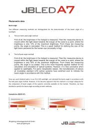
1. Technische Daten / Technical data<br />
128<br />
86<br />
318<br />
8<br />
310<br />
388<br />
200<br />
276<br />
315<br />
130<br />
Kopf / head<br />
Arm / yoke<br />
Sicherung / fuse<br />
Netzanschluß / Power cable entry<br />
DMX in/out Buchsen / connectors<br />
Sicherungsöse / safety cable<br />
attachment point<br />
Bedienfeld / control panel<br />
Gewicht / weight:<br />
8,9kg (19,6 lbs.)<br />
Netzanschluß / power connection: 1 00-240VAC, 47-63Hz<br />
(Sicherung / Fuse 6,3A)<br />
Stromaufnahme / power consumption: max. 220VA<br />
Wärmestrom / heat flow:<br />
max. 220W<br />
Umgebungstemp. / ambient temp.: Max. 40°C (104°F)<br />
min. 5°C (41°F)<br />
2
Inhaltsverzeichnis<br />
Deutsch<br />
1. Technische Daten............................................................... 2<br />
2. Einleitung............................................................................ 4<br />
2.1 Sicherheitshinweise................................................ 4<br />
2.2 Auspacken der Geräte............................................ 4<br />
3. Installation.......................................................................... 5<br />
3.1 Netzstecker montieren............................................ 5<br />
3.2 Montage der Geräte................................................ 5<br />
3.3 DMX Verkabelung................................................... 6<br />
3.4 Netzstrom verkabeln............................................... 6<br />
4. Bedienfeld........................................................................... 7<br />
4.1 Menü Übersicht....................................................... 8<br />
4.2 DEFAULTS - Parameter zurücksetzen................... 9<br />
4.3 DMX ADDRESS - DMX Adressierung.................... 9<br />
4.4 PERSONALITY - Persönliche Einstellungen.......... 9<br />
4.5 DMX Test................................................................ 10<br />
4.6 INFO....................................................................... 10<br />
4.7 Standalone-Betrieb................................................. 10<br />
5. Kanalbelegung................................................................... 12<br />
6. Service................................................................................ 15<br />
6.1 Servicemenü........................................................... 15<br />
6.2 Gerät reinigen......................................................... 16<br />
6.3 Software Update..................................................... 17<br />
6.4 Prüfen von Elektrischen Betriebsmitteln................. 17<br />
7. Konformitätserklärung...................................................... 18<br />
Contents<br />
English<br />
1. Technical Data........................................................... 2<br />
2. Introduction............................................................... 20<br />
2.1 Safety instruction............................................ 20<br />
2.2 Unpacking....................................................... 20<br />
3. Installation................................................................. 21<br />
3.1 Powering the fixture........................................ 21<br />
3.2 Rigging the fixture........................................... 21<br />
3.3 DMX wiring...................................................... 22<br />
3.4 Install a plug on the power cord...................... 22<br />
4. Control panel............................................................. 23<br />
4.1 Menu navigation............................................. 24<br />
4.2 DEFAULTS - Set to factory default................. 25<br />
4.3 DMX ADDRESS - DMX addressing................ 25<br />
4.4 PERSONALITY............................................... 25<br />
4.5 DMX Test........................................................ 26<br />
4.6 INFO............................................................... 26<br />
4.7 Standalone mode............................................ 26<br />
5. DMX Protocol............................................................ 28<br />
6. Service....................................................................... 31<br />
6.1 Service menu................................................ 31<br />
6.2 Cleaning the fixture......................................... 32<br />
6.3 Software update.............................................. 32<br />
6.4 Verifying electronic devices............................. 33<br />
7. Declaration of conformity......................................... 34<br />
3
2. Einleitung<br />
2.1 Sicherheitshinweise<br />
!<br />
ACHTUNG:<br />
Dieses Gerät ist nur für den professionellen Gebrauch geeignet!<br />
LED Strahlung - Nicht <strong>im</strong> Abstand von weniger als 0,5m und nicht<br />
mit optischen Instrumenten in den Strahl blicken.<br />
LED-Klasse 2M<br />
!<br />
ACHTUNG:<br />
<strong>JB</strong>-<strong>lighting</strong> <strong>Lichtanlagentechnik</strong> <strong>GmbH</strong> autorisiert den Gebrauch ihrer<br />
Geräte nicht in lebensunterstützenden Systemen.<br />
Lebensunterstützende Systeme sind Systeme deren Zweck dazu dient<br />
Leben zu erhalten oder zu stabilisieren und deren Defekt oder Fehlfunktion<br />
möglicherweise den Tod oder die Verletzung einer Person nach sich<br />
ziehen.<br />
Das Produkt dieser Bedienungsanleitung entspricht folgender<br />
EU-Richtlinien:<br />
- Niederspannungsrichtlinie 2006/95/CE<br />
- EMV 89/336<br />
2.2 Auspacken des Gerätes<br />
Inhalt der Versandverpackung: dieser Scheinwerfer und zwei Omega-Bügel mit Bajonett-<br />
Verschlüssen.<br />
Öffnen Sie die Verpackung an der Oberseite und entnehmen Sie das Inlay mit den beiden<br />
Omega-Bügeln. Überprüfen Sie den <strong><strong>JB</strong>LED</strong> <strong>A4</strong> auf eventuelle Transportschäden, die umgehend<br />
dem Transportunternehmen mitgeteilt werden müssen.<br />
4
3. Installation<br />
3.1 Netzstecker montieren<br />
!<br />
ACHTUNG: Nur von einem Fachmann durchführen lassen!<br />
Die Montage des Schutzkontaktsteckers, bzw. der Anschluss des <strong><strong>JB</strong>LED</strong>A7 an die Stromversorgung<br />
(100-240 Volt, 47-63 Hertz), muß von einem autorisierten Fachmann durchgeführt<br />
werden.<br />
EU Model: US Model:<br />
Braun Schwarz Phase “L”<br />
Blau Weiß Nulleiter “N”<br />
Grün/Gelb Grün Schutzleiter<br />
3.2 Montage der Geräte<br />
!<br />
ACHTUNG: Mindestens 0,5 m Abstand zu brennbaren Gegenständen!<br />
<strong><strong>JB</strong>LED</strong> <strong>A4</strong> <strong>im</strong>mer mit Sicherungsseil zusätzlich sichern!<br />
Der <strong><strong>JB</strong>LED</strong> <strong>A4</strong> darf stehend nur auf einer harten Unterlage betrieben werden, die <strong>im</strong> Bodenblech<br />
eingestanzten Lüftungsschlitze müssen frei bleiben. Bei Verwendung der standard<br />
Omega Bügel kann der <strong><strong>JB</strong>LED</strong> <strong>A4</strong> in beliebiger Position montiert werden. Verwenden<br />
Sie bei der Montage <strong>im</strong>mer beide standard Omega-Bügel. Achten Sie darauf, das die<br />
Camlocs richtig eingerastet sind. Optional wird ein diagonaler Omega-Bügel angeboten.<br />
Mit diesem darf der <strong><strong>JB</strong>LED</strong> <strong>A4</strong> ausschließlich lotrecht oder stehend befestigt werden. Den<br />
<strong><strong>JB</strong>LED</strong> <strong>A4</strong> <strong>im</strong>mer zusätzlich mit Sicherungsseil an der Sicherungsöse sichern.<br />
140<br />
Omega Bügel<br />
Camloc<br />
140<br />
224<br />
Sicherungsöse<br />
5
3.3 DMX Verkabelung<br />
Die DMX Verkabelung (Signalleitungen) sollte mit einem 4-poligen Kabel mit Abschirmung<br />
erfolgen. Wir empfehlen ein DMX-Kabel, alternativ kann auch ein 2-poliges Mikro-Kabel<br />
verwendet werden. Damit ist jedoch kein Software-Update möglich, da Pin 4 und 5 nicht<br />
belegt sind. Bei den Steckern und Buchsen handelt es sich um 5-polige oder 3-polige<br />
XLR Verbinder, die <strong>im</strong> Fachhandel erworben werden können.<br />
Steckerbelegung<br />
1<br />
1<br />
Pin 1 = Ground = Abschirmung 2 Kabel mit Abschirmung 2<br />
Pin 2 = DMX -<br />
Pin 3 = DMX +<br />
3<br />
3<br />
Pin 4 = Data out -<br />
4<br />
4<br />
Pin 5 = Data out +<br />
5<br />
5<br />
Der <strong><strong>JB</strong>LED</strong> <strong>A4</strong> verfügt über je zwei DMX-in und DMX-out Anschlüsse, die jeweils parallel<br />
durchkontaktiert sind. Benutzen Sie pro Scheinwerfer jeweils nur eine DMX-in und DMXout<br />
Anschluss!<br />
Die Geräte können nicht als DMX-Splitter benutzt werden.<br />
Verbinden Sie nun den DMX-Ausgang Ihres Controllers mit dem 1. <strong><strong>JB</strong>LED</strong> <strong>A4</strong>. (Controller<br />
DMX-Out mit <strong><strong>JB</strong>LED</strong> <strong>A4</strong> DMX-In). Anschließend den 1. <strong><strong>JB</strong>LED</strong> <strong>A4</strong> mit dem 2. <strong><strong>JB</strong>LED</strong> <strong>A4</strong><br />
(<strong><strong>JB</strong>LED</strong> <strong>A4</strong> 1 DMX-Out mit <strong><strong>JB</strong>LED</strong> <strong>A4</strong> 2 DMX-In) und so weiter.<br />
Alle DMX-Ein/Ausgänge sind durchkontaktiert, d.h. Sie können den 3-poligen DMX-In in<br />
Kombination mit dem 5-poligen DMX-Out Anschluss benutzen.<br />
In manchen Fällen ist es ratsam einen so genannten Endstecker (XLR-Stecker mit einem<br />
Widerstand von 120 Ohm zwischen Pin 2 und Pin 3) einzustecken. Ob ein Endstecker benötigt<br />
wird hängt von verschiedenen Faktoren (unter anderem den benutzten Kabellängen<br />
und der Geräte Anzahl ab). Solange jedoch keine Probleme in der DMX-Linie auftreten,<br />
kann darauf verzichtet werden.<br />
3.4 Netzstrom verkabeln<br />
Netzstecker montieren siehe Kapitel 2.1.<br />
Anschlußwerte: Spannung 100-240 V, Frequenz 47-63 Hz, Leistung max. 220VA<br />
Die elektrische Sicherheit sowie die Funktion des Gerätes ist nur dann gewährleistet,<br />
wenn es an ein vorschriftsmäßig installiertes Schutzleitersystem angeschlossen wird. Es<br />
ist sehr wichtig, daß diese grundlegende Sicherheitsvoraussetzung vorhanden ist. Lassen<br />
Sie <strong>im</strong> Zweifelsfall die Elektroinstallation durch einen Fachmann überprüfen. Der Hersteller<br />
kann nicht für Schäden verantwortlich gemacht werden, die durch einen fehlenden<br />
oder unterbrochenen Schutzleiter verursacht wurden! (z. B. Elektrischer Schlag). Benutzen<br />
Sie das Gerät nur <strong>im</strong> komplett zusammengebauten Zustand, damit keine elektrischen<br />
Bauteile berührt werden können. ( Gefahr 100-240 V)<br />
Wenn Sie die aufgeführten Punkte beachtet haben, können Sie die Geräte einstecken,<br />
oder von einem Fachmann an das Netz anschließen lassen.<br />
!<br />
ACHTUNG:<br />
<strong><strong>JB</strong>LED</strong> <strong>A4</strong> kann sofort aufleuchten falls Standalone-Betrieb aktiviert ist<br />
oder DMX-Signal anliegt!<br />
6
4. Bedienfeld<br />
Der <strong><strong>JB</strong>LED</strong> <strong>A4</strong> verfügt über ein grafisches Display, dass bei Überkopf-Installation um 180°<br />
gedreht werden kann.<br />
Drehen des Displays<br />
<strong><strong>JB</strong>LED</strong> <strong>A4</strong><br />
ESC<br />
<strong>JB</strong> - LIGHTING<br />
S8<br />
001<br />
DOWN UP ENTER<br />
<strong><strong>JB</strong>LED</strong> <strong>A4</strong><br />
<strong>JB</strong> - LIGHTING<br />
S8<br />
001<br />
ESC DOWN UP ENTER<br />
Die aktuelle Ausrichtung des Displays wird durch Drücken der Display-Tasten best<strong>im</strong>mt.<br />
Die Display Beschriftung orientiert sich <strong>im</strong>mer zu der Tastenreihe, die benutzt wird.<br />
Am Bedienfeld können sämtliche Parameter des <strong><strong>JB</strong>LED</strong> <strong>A4</strong> eingestellt werden (siehe<br />
Menü-Übersicht nächste Seite).<br />
Im Hauptmenü lässt sich die Adresse direkt einstellen. Durch Drücken der rechten Base<br />
Taste be<strong>im</strong> einstecken des <strong><strong>JB</strong>LED</strong> <strong>A4</strong> wird überdies der Resetvorgang abgebrochen damit<br />
eine adressierung auch <strong>im</strong> Case erfolgen kann. Ebenso informiert das Hauptmenü über<br />
den eingestellten DMX-Mode und bei eingeschaltetem Wireless Mode über die Feldstärke<br />
des zugehörigen Sendemoduls.<br />
Durch “ENTER” wird ein Untermenü aufgerufen oder eine Eingabe bestätigt, “ESC” dient<br />
zum Verlassen einer Funktion oder eines Menüpunktes, "UP" und "DOWN" dient zum Navigieren<br />
innerhalb des Menüs und zur Eingabe von Werten.<br />
Besondere Bereiche können nur über eine Tastenkombination aufgerufen werden. Dabei<br />
wird die Taste “ENTER” gedrückt (und gedrückt gehalten) und dann zusätzlich mit der<br />
“gegenüberliegenden” Taste “ESC” der Zugang zum Menü freigeschaltet. Das Verlassen<br />
der Funktion erfolgt dann in umgekehrter Reihenfolge.<br />
Dies gilt <strong>im</strong> SERVICE-Bereich für die Funktion FINE ADJUST, sowie <strong>im</strong> STANDALONE<br />
Bereich für die Funktionen MODIFY , RUN und REMOTE.<br />
Außerdem lässt sich das Hauptmenü gegen unbeabsichtigten Zugriff sperren. Die Sperrung<br />
erfolgt ebenfalls durch Drücken der Taste “ENTER” (gedrückt gehalten) und dann zusätzlich<br />
mit der “gegenüberliegenden” Taste “ESC” sperren.<br />
Der Displaybeleuchtung werden besondere Funktionen zugeordnet:<br />
Während des Resets bleibt die Displaybeleuchtung ausgeschaltet.<br />
Langsam blinkende Displaybeleuchtung bei der Anzeige <strong>JB</strong>-LIGHTING bedeutet es liegt<br />
kein DMX-Signal an.<br />
Schnell blinkende Displaybeleuchtung bei der Anzeige <strong>JB</strong>-LIGHTING bedeutet, in der<br />
"ERROR LIST" ist ein Fehler abgespeichert, der noch nicht gelöscht wurde (Löschen<br />
siehe Seite 8 Menü Übersicht - Service). Schnell blinkende Displaybeleuchtung bei einer<br />
Fehlermeldung <strong>im</strong> Display (z.B. * PAN TIMEOUT) zeigt einen aktuellen Fehler an, wenden<br />
Sie sich an Ihren Händler oder unsere Serviceabteilung.<br />
Empfängt der <strong><strong>JB</strong>LED</strong> <strong>A4</strong> ein DMX-Signal erlischt die Displaybeleuchtung nach 30 Sekunden.<br />
7
4.1 Menü-Übersicht<br />
Taste Enter<br />
DEFAULTS<br />
Enter<br />
LOAD DEFAULTS<br />
Enter<br />
SURE ?<br />
+<br />
DMX ADDRESS<br />
ADDRESS +/-<br />
PERSONALITY<br />
DMX INPUT MODE<br />
DMX MODE<br />
PAN/TILT<br />
CURVES<br />
SHORTEST DIST.<br />
CAMERA MODE<br />
COOLING MODE<br />
WIRED<br />
WIRED/WIRELESS<br />
STANDARD RGB8<br />
STANDARD RGB16<br />
COMPR. RGB8<br />
COMPR. RGB16<br />
RESOLUTION<br />
PAN INVERS<br />
TILT INVERS<br />
PAN/TILT SWAP<br />
DIMMER CURVE<br />
RGB CURVE<br />
ON<br />
OFF<br />
50 HZ<br />
60 HZ<br />
FLEX<br />
STANDARD<br />
SILENT<br />
HI-POWER<br />
16 BIT<br />
8 BIT<br />
NORMAL<br />
INVERS<br />
NORMAL<br />
INVERS<br />
NORMAL<br />
INVERS<br />
SQUARE<br />
LINEAR<br />
SQUARE<br />
LINEAR<br />
SERVICE<br />
RESET FIXTURE<br />
ERROR LIST<br />
FUNCTIONS TEST<br />
DMX TEST<br />
INIT PAN TILT<br />
FINE ADJUST<br />
RECEIVESOFT<br />
LIST<br />
CLEAR<br />
START TEST<br />
DMX CHANNEL<br />
SURE ?<br />
SKAL RED<br />
SKAL GREEN<br />
SKAL BLUE<br />
SKAL ALL<br />
OFS ZOOM<br />
SURE ?<br />
PAN TIMEOUT<br />
SURE ?<br />
TEST RUNNING...<br />
COUNT : 1<br />
CLEAR?<br />
STANDALONE<br />
EDIT<br />
RUN<br />
TIMEBASE<br />
REMOTE<br />
STEP NR. +/-<br />
1 SEC<br />
1/10 SEC<br />
MODIFY<br />
CAPT DMX<br />
INSERT<br />
DELETE<br />
RESET STEP<br />
CLEAR ALL<br />
FADE TIME<br />
NEXT TIME<br />
PAN<br />
TILT<br />
CONTROL<br />
FADE TIME<br />
NEXT TIME<br />
PAN<br />
TILT<br />
CONTROL<br />
+/-<br />
+/-<br />
+/-<br />
+/-<br />
+/-<br />
SHUTTER<br />
SHUTTER +/-<br />
DIMMER<br />
DIMMER +/-<br />
ZOOM ZOOM +/-<br />
RED<br />
RED<br />
+/-<br />
GREEN<br />
GREEN +/-<br />
BLUE<br />
BLUE +/-<br />
CTC<br />
CTC<br />
+/-<br />
COLOR<br />
COLOR +/-<br />
SPEED P/T<br />
SPEED P/T +/-<br />
SPEED EFF<br />
SPEED EFF +/-<br />
MOVE B-OUT<br />
MOVE B-OUT +/-<br />
INFO<br />
SOFTWARE VERSION<br />
FIRMWARE VERSION<br />
TOT OPERATE TIME<br />
TEMP BASE LCD<br />
TEMP BASE PS<br />
TEMP HEAD DRV<br />
TEMP HEAD LED<br />
ACTUAL<br />
MAX RESET ?<br />
ACTUAL<br />
MAX<br />
RESET ?<br />
ACTUAL<br />
MAX<br />
RESET ?<br />
ACTUAL<br />
MAX<br />
RESET ?<br />
8
4.2 DEFAULTS - Parameter zurücksetzen<br />
Um den <strong><strong>JB</strong>LED</strong> <strong>A4</strong> auf die Werkseinstellung zurück zu setzen, gehen Sie auf den Menüpunkt<br />
FACTORY DEFAULTS, LOAD DEFAULTS. Nach dem Bestätigen der Sicherheitsabfrage<br />
SURE? mit “ENTER” werden alle Parameter auf Werkseinstellung zurück gesetzt.<br />
Der aktuelle Weißabgleich (Kapitel 5.3) bleibt bei der Rücksetzung erhalten.<br />
4.3 DMX ADDRESS - DMX Adressierung<br />
Die DMX Adressierung kann direkt <strong>im</strong> Display vorgenommen werden. Durch Drücken der<br />
Taste "UP" oder "DOWN" stellen Sie die gewünschte DMX-Adresse ein. Mit der Taste<br />
"ENTER" wird der Wert bestätigt. Die DMX Adressierung kann aber auch innerhalb des<br />
Menüs unter DMX ADDRESS vorgenommen werden.<br />
4.4 PERSONALITY - Persönliche Einstellungen<br />
DMX INPUT MODE<br />
Im <strong><strong>JB</strong>LED</strong> <strong>A4</strong> ist werksseitig ein Wireless DMX Empfangsmodul eingebaut. Um dieses in<br />
Verbindung mit dem <strong>JB</strong>-<strong>lighting</strong> Wireless TRX Sendemodul zu benutzen lässt sich der<br />
Menüpunkt WIRED (Werkseinstellung) auf WIRED/WIRELESS umstellen. Der Login des<br />
Empfängers auf den Sender erfolgt über die „Start“ Taste (siehe hierzu Bedienungsanleitung<br />
Wireless TRX). Hat sich das Gerät eingeloggt wird der entsprechende Funkkanal angezeigt,<br />
eine Pegelanzeige <strong>im</strong> Display informiert über die aktuelle Empfangsqualität. Wird der<br />
<strong><strong>JB</strong>LED</strong> <strong>A4</strong> zusätzlich über die DMX Anschlussbuchsen angeschlossen, so hat dieses Signal<br />
Priorität vor der Funkstrecke.<br />
DMX MODE<br />
Der <strong><strong>JB</strong>LED</strong> <strong>A4</strong> verfügt über 4 Betriebsmodi (siehe Kanalbelegung S. 12). Über die Modi<br />
Standard 8 BIT und Standard 16 BIT lassen sich alle Parameter des <strong><strong>JB</strong>LED</strong> <strong>A4</strong> bedienen.<br />
Die Wahlmöglichkeit zwischen 8 BIT und 16 BIT dient zur Umschaltung der RGB Ansteuerung.<br />
Im 16 BIT Modus lassen sich die Farbkanäle feiner justieren. Um die Farbeinstellung<br />
zu vereinfachen und DMX-Kanäle einzusparen lässt sich der <strong><strong>JB</strong>LED</strong> <strong>A4</strong> auf 2 kompr<strong>im</strong>ierte<br />
Modi (C8, C16) umstellen. Die Kanäle Farbmakro, Farbrad, Pan/Tilt Geschwindigkeit,<br />
Effektgeschwindigkeit und Blackout move werden dabei ausgeblendet, sodaß die<br />
Farbeinstellung nurmehr über RGB einstellbar ist.<br />
PAN / TILT<br />
Unter RESOLUTION lässt sich die Bewegungsauflösung von 16 Bit auf 8 Bit einstellen. In<br />
der Werkseinstellung ist diese auf 16 Bit eingestellt. In der 8 Bit Auflösung lässt sich der<br />
<strong><strong>JB</strong>LED</strong> <strong>A4</strong> weniger exakt Positionieren, je nach Lichtkonsole jedoch schneller durchscrollen.<br />
Die Menüpunkte PAN INVERS und TILT INVERS ermöglichen ein Invertieren der Bewegungsrichtung.<br />
Unter PAN/TILT SWAP lassen sich die Kanäle Pan und Tilt tauschen.<br />
CURVES<br />
Die D<strong>im</strong>merkurve, sowie die RGB Farbmischungskurve lassen sich jeweils von Exponential<br />
(square) auf Linear umstellen. In der Exponentialkurve (Werkseinstellung) bewirkt dies<br />
ein weicheres Ein- und Ausblendverhalten des D<strong>im</strong>mers, sowie ein sanfteres Überblenden<br />
der RGB Farbmischung insbesondere be<strong>im</strong> Einsatz von Farbverlaufseffekten über Effect<br />
engines.<br />
SHORTEST DISTANCE<br />
Dieser Menüpunkt spricht nur auf den Farbradkanal an. Der Farbradkanal s<strong>im</strong>uliert das<br />
Farbrad unserer konventionellen Moving Heads. In der Werkseinstellung (ON) wechseln<br />
die Farben über die kürzeste Distanz zueinander. Ein umstellen auf OFF bewirkt das der<br />
Farbwechsel nur über die konventionelle Reihenfolge erfolgt.<br />
9
CAMERA MODE<br />
Um ein Fl<strong>im</strong>mern bei TV Aufnahmen zu vermeiden, lässt sich der <strong><strong>JB</strong>LED</strong> <strong>A4</strong> an verschiedene<br />
Kamerasysteme von 50 Hertz (PAL, Secam) auf 60 Hertz (NTSC) anpassen. Der<br />
Flex Mode wird eingestellt falls abweichende Kamerasysteme benutzt werden. Dies ist<br />
auch über den Controlkanal übers Lichtmischpult steuerbar.<br />
COOLING MODE<br />
Im Menüpunkt COOLING MODE lässt sich die Lüftersteuerung des <strong><strong>JB</strong>LED</strong> <strong>A4</strong> einstellen.<br />
Die STANDARD - Einstellung sollte in den meisten Fällen gewählt werden. Mit der Umschaltung<br />
auf SILENT lassen sich die Lüftergeräusche auf ein Min<strong>im</strong>um reduzieren.<br />
Der Zeitraum für diese Einstellung sollte begrenzt sein und nur in ausreichend belüfteten<br />
Räumen benutzt werden. Bei Festinstallationen, sowie schlecht belüfteten Räumen sollte<br />
der HI POWER Mode eingestellt werden.<br />
Eine Gefahr für die Lebensdauer des Geräts besteht in keinem Modus, da der <strong><strong>JB</strong>LED</strong> <strong>A4</strong><br />
über eine Temperatur Sicherheitsabschaltung verfügt.<br />
4.5 INFO<br />
Hier werden Sie über den jeweiligen Software- und Firmwarestand informiert.<br />
Im Menüpunkt TOT OPERATE TIME werden die Gesamtstunden des <strong><strong>JB</strong>LED</strong> <strong>A4</strong> gespeichert.<br />
Diese können nicht zurückgesetzt werden.<br />
Der <strong><strong>JB</strong>LED</strong> <strong>A4</strong> überprüft laufend über Temperatursensoren seine Betriebstemperatur.<br />
Diese können in folgenden Bereichen ausgelesen werden:<br />
TEMP BASE LCD - Leiterkarte Bedienfeld<br />
TEMP BASE PS - Netzteil<br />
TEMP HEAD DRV - LED Treiberplatine<br />
TEMP HEAD LED - LED Platine<br />
Es wird jeweils die aktuelle sowie die max<strong>im</strong>ale Temperatur angezeigt. Diese kann einzeln<br />
gelöscht werden.<br />
4.6 Standalone-Betrieb<br />
Im Standalone-Betrieb können bis zu 20 Programmschritte <strong>im</strong> <strong><strong>JB</strong>LED</strong> <strong>A4</strong> gespeichert werden,<br />
die dann als Endlosschleife ablaufen. Die Speicherung der Bilder kann dabei auf zwei<br />
Arten erfolgen. Entweder Sie stellen die gewünschten DMX-Werte direkt am <strong><strong>JB</strong>LED</strong> <strong>A4</strong> ein<br />
und speichern diese ab, oder Sie stellen die DMX-Werte über ein angeschlossenes DMX-<br />
Pult ein und speichern diese anschließend <strong>im</strong> <strong><strong>JB</strong>LED</strong> <strong>A4</strong> ab.<br />
Die Menüpunkte MODIFY , RUN und REMOTE können nur mit Hilfe einer Tastenkombination<br />
aufgerufen werden. Dazu Drücken Sie “ENTER”, halten die Taste gedrückt und<br />
drücken zusätzlich "ESC".<br />
Entfernen Sie vor dem Aktivieren dieser Menü-Punkte alle anderen Geräte in der DMX-<br />
Linie, die DMX senden, wie z.B. Pulte oder andere <strong><strong>JB</strong>LED</strong> <strong>A4</strong>, die nicht als Slave-Geräte<br />
konfiguriert sind, da sonst ggfls. Beschädigungen an den DMX-Treibern auftreten können.<br />
Programmieren des Standalone Programms am Scheinwerfer-Display:<br />
Rufen Sie den Menüpunkt STANDALONE, EDIT auf. Im Menüpunkt STEP NR+/- wählen<br />
Sie den gewünschten Step aus und können diesen und seine Kanalparameter in den<br />
folgen den Menüpunkten verändern:<br />
Im Menüpunkt MODIFY stellen Sie die gewünschte Lichtst<strong>im</strong>mung und Position ein und<br />
best<strong>im</strong>men mit FADE TIME (Einblendzeit) und NEXT TIME (Zeit des gesamten Schritts)<br />
die einzelnen Ablaufzeiten der Schritte.<br />
10
Mit INSERT fügen Sie einen zusätzlichen Programmschritt ein. Die DMX-Werte des vorigen<br />
Schritts werden in den neuen Schritt kopiert.<br />
Mit DELETE löschen Sie einen Schritt heraus. Das Display zeigt Ihnen dabei STEP NR:<br />
1/X an. Mit den Auswahltasten gehen Sie dabei auf den gewünschten Schritt.<br />
Mit RESET STEP setzen Sie einen Schritt auf seinen Ursprungswert (DMX 000) zurück.<br />
Das Display zeigt Ihnen dabei STEP NR: 1/X an. Mit den Auswahltasten suchen Sie sich<br />
Ihren Schritt aus.<br />
Mit CLEAR ALL setzen Sie die kompletten Standalone Schritte zurück. Unter MODIFY<br />
finden Sie danach wieder STEP1/1.<br />
Im Menüpunkt STANALONE, TIMEBASE haben Sie die Möglichkeit die Fade T<strong>im</strong>e und<br />
Next T<strong>im</strong>e von 1 Sekunde auf 1/10 Sekunde umzustellen.<br />
Übernehmen der DMX Werte von einem externen Pult:<br />
Um die DMX-Werte eines angeschlossenen Pultes zu übernehmen müssen Sie zuerst den<br />
Capture DMX Eingang freischalten. Hierzu gehen Sie zum Menüpunkt CAPT DMX. Das<br />
Display zeigt Ihnen jetzt CAPTURE DMX 01/01, mit der Übernahmetaste schalten Sie auf<br />
START CAPTURE. Nun reagiert der <strong><strong>JB</strong>LED</strong> <strong>A4</strong> auf die Signale des externen Pultes.<br />
Aktivieren des Standalone Betriebs:<br />
Rufen Sie das STANDALONE MENU auf und navigieren Sie bis zum Untermenü RUN.<br />
Bestätigen Sie durch die Tastenkombination “ENTER” drücken und gedrückt halten und<br />
gleichzeitig “ESC” drücken. Das Display zeigt dann: S-ALONE: 01/XX und das Programm<br />
läuft in einer Endlosschleife ab.<br />
Deaktivieren: Drücken Sie die Taste “ESC”, halten Sie diese gedrückt und drücken Sie<br />
dann zusätzlich “ENTER”. Das Menü springt eine Ebene zurück und RUN wird <strong>im</strong> Display<br />
dargestellt.<br />
Betrieb über Master-Slave Funktion:<br />
Verbinden Sie die <strong><strong>JB</strong>LED</strong> <strong>A4</strong> über DMX Leitungen, aktivieren Sie bei allen Slave-Geräten<br />
den Menüpunkt REMOTE. Navigieren Sie dazu <strong>im</strong> STANDALONE MENÜ bis zum Untermenü<br />
REMOTE. Aktivieren Sie die Funktion REMOTE durch die Tastenkombination<br />
“ENTER” drücken, gedrückt halten und zusätzlich “ESC” drücken. Der Scheinwerfer befindet<br />
sich <strong>im</strong> Slave-Modus, wenn <strong>im</strong> Display der Status REMOTE INACTIVE oder REMOTE<br />
ACTIVE dargestellt wird. REMOTE INACTIVE: <strong><strong>JB</strong>LED</strong> <strong>A4</strong> befindet sich <strong>im</strong> Slave-Modus<br />
empfängt aber kein DMX-Signal<br />
REMOTE ACTIVE: <strong><strong>JB</strong>LED</strong> <strong>A4</strong> befindet sich <strong>im</strong> Slave-Modus und empfängt ein DMX-<br />
Signal. Das Master-Gerät wird über den Menüpunkt MODIFY programmiert und über RUN<br />
(durch die Tastenkombination “ENTER” drücken, gedrückt halten und zusätzlich “ESC”<br />
drücken) gestartet.<br />
11
5. Kanalbelegung<br />
Der <strong><strong>JB</strong>LED</strong> <strong>A4</strong> verfügt über 4 unterschiedliche Kanaloptionen. Der jeweilige Modus lässt<br />
sich <strong>im</strong> Menüpunkt PERSONALITY, DMX MODE einstellen. Der eingestellte Mode wird<br />
<strong>im</strong> Hauptmenü angezeigt.<br />
STANDARD RGB 8 BIT (S8)<br />
Kanal 1 Pan<br />
Kanal 2 Pan fein<br />
Kanal 3 Tilt<br />
Kanal 4 Tilt fein<br />
Kanal 5 Control<br />
Kanal 6 Shutter<br />
Kanal 7 D<strong>im</strong>mer<br />
Kanal 8 Zoom<br />
Kanal 9 Rot<br />
Kanal 10 Grün<br />
Kanal 11 Blau<br />
Kanal 12 CTC<br />
Kanal 13 Farbrad<br />
Kanal 14 Pan/Tilt Geschwindigkeit<br />
Kanal 15 Effektgeschwindigkeit<br />
Kanal 16 Blackout Move<br />
COMPRESSED RGB 8 BIT (C8)<br />
Kanal 1 Pan<br />
Kanal 2 Pan fein<br />
Kanal 3 Tilt<br />
Kanal 4 Tilt fein<br />
Kanal 5 Control<br />
Kanal 6 Shutter<br />
Kanal 7 D<strong>im</strong>mer<br />
Kanal 8 Zoom<br />
Kanal 9 Rot<br />
Kanal 10 Grün<br />
Kanal 11 Blau<br />
Kanal 12 CTC<br />
STANDARD RGB 16 BIT (S16)<br />
Kanal 1 Pan<br />
Kanal 2 Pan fein<br />
Kanal 3 Tilt<br />
Kanal 4 Tilt fein<br />
Kanal 5 Control<br />
Kanal 6 Shutter<br />
Kanal 7 D<strong>im</strong>mer<br />
Kanal 8 Zoom<br />
Kanal 9 Rot<br />
Kanal 10 Rot fein<br />
Kanal 11 Grün<br />
Kanal 12 Grün fein<br />
Kanal 13 Blau<br />
Kanal 14 Blau fein<br />
Kanal 15 CTC<br />
Kanal 16 Farbrad<br />
Kanal 17 Pan/Tilt Geschwindigkeit<br />
Kanal 18 Effektgeschwindigkeit<br />
Kanal 19 Blackout Move<br />
COMPRESSED RGB 16 BIT (C16)<br />
Kanal 1 Pan<br />
Kanal 2 Pan fein<br />
Kanal 3 Tilt<br />
Kanal 4 Tilt fein<br />
Kanal 5 Control<br />
Kanal 6 Shutter<br />
Kanal 7 D<strong>im</strong>mer<br />
Kanal 8 Zoom<br />
Kanal 9 Rot<br />
Kanal 10 Rot fein<br />
Kanal 11 Grün<br />
Kanal 12 Grün fein<br />
Kanal 13 Blau<br />
Kanal 14 Blau fein<br />
Kanal 15 CTC<br />
12
Aufteilung der einzelnen Kanäle<br />
S8 S16 C8 C16 Funktion<br />
1 1 1 1 Pan (X) Bewegung 430°<br />
DMX<br />
000-255<br />
2 2 2 2<br />
3 3 3 3<br />
4 4 4 4<br />
5 5 5 5<br />
6 6 6 6<br />
7 7 7 7<br />
8 8 8 8<br />
Pan (X) fein<br />
Tilt (Y) Bewegung 300°<br />
Tilt (Y) fein<br />
Control<br />
100% Ausgangsleistung der LED Stränge<br />
Fade out über Fader (langsam - schnell)<br />
Farbabgleich auf RGB (weiss 8500K)<br />
Fade out über Fader (langsam - schnell)<br />
Farbabgleich auf RGB (weiss 6500K)<br />
Fade out über Fader (langsam - schnell)<br />
Farbabgleich für Colour Picker<br />
Fade out über Fader (langsam - schnell)<br />
Sicherheit<br />
Camera Mode, 50Hz (nach 2 Sekunden)<br />
Camera Mode, 60Hz (nach 2 Sekunden)<br />
Camera Mode, FLEX (nach 2 Sekunden)<br />
Sicherheit<br />
Reset (nach 2 Sekunden)<br />
Sicherheit<br />
Shutter<br />
Shutter zu<br />
Shutter auf<br />
Shutter pulsierend öffnen >10Hz (0,6sec - 4,8sec)<br />
Shutter auf<br />
Fade-Effekt mit D<strong>im</strong>mer (langsam - schnell)<br />
Shutter auf<br />
Shutter zu<br />
Shutter pulsierend öffnen
S8 S16 C8 C16<br />
9 9 9 9<br />
10 10<br />
10 11 10 11<br />
12 12<br />
11 13 11 13<br />
14 14<br />
12 15 12 15<br />
13 16<br />
14 17<br />
Funktion<br />
Rot (8 Bit) 0 - 100%<br />
Rot, fein (16 Bit) 0 - 100%<br />
Grün (8 BIT) 0 - 100%<br />
Grün, fein (16 BIT) 0 - 100%<br />
Blau (8 BIT) 0 - 100%<br />
Blau, fein (16 BIT) 0 - 100%<br />
CTC 0 - 100%<br />
Farbrad<br />
inaktiv, Farbmischung nur über RGB<br />
weiss<br />
weiss/rot<br />
rot<br />
rot/gelb<br />
gelb<br />
gelb/magenta<br />
magenta<br />
magenta/grün<br />
grün<br />
grün/orange<br />
orange<br />
orange/blau<br />
blau<br />
blau/türkis<br />
türkis<br />
türkis/weiss<br />
Farben stufenlos positionieren<br />
Farbraddreh rechts (schnell - langsam)<br />
Farbraddreh stop<br />
Farbraddreh links (langsam - schnell)<br />
Pan/Tilt Geschwindigkeit<br />
Bewegung in Echtzeit<br />
Bewegung zeitverzögert (schnell - langsam)<br />
DMX<br />
000-255<br />
000-255<br />
000-255<br />
000-255<br />
000-255<br />
000-255<br />
000-255<br />
000-001<br />
002-003<br />
004-007<br />
008-011<br />
012-015<br />
016-019<br />
020-023<br />
024-027<br />
028-031<br />
032-035<br />
036-039<br />
040-043<br />
044-047<br />
048-051<br />
052-055<br />
056-059<br />
060-063<br />
064-191<br />
192-222<br />
223-224<br />
225-255<br />
000-003<br />
004-255<br />
15 18<br />
Effektgeschwindigkeit<br />
Effekte in Echtzeit<br />
Effekte zeitverzögert<br />
(schnell - langsam)<br />
000-003<br />
004-255<br />
16 19<br />
Blackout Move<br />
keine Funktion<br />
D<strong>im</strong>mer schließt bei Bewegung P/T<br />
D<strong>im</strong>mer schließt bei Farbwechsel<br />
keine Funktion<br />
D<strong>im</strong>mer schließt bei Farbwechsel, Bew. P/T<br />
Die Fadezeit des D<strong>im</strong>mers ist einstellbar von<br />
langsam 5sec - max.<br />
000-095<br />
096-127<br />
128-159<br />
160-223<br />
224-255<br />
14
Hinweis!<br />
Der <strong><strong>JB</strong>LED</strong> <strong>A4</strong> verfügt über einen Farbradkanal, RGB Farbmischung sowie einen CTC<br />
Kanal. Um die Funktionen zu überschauen sind diese mit unterschiedlichen Prioritäten<br />
belegt. Der Farbradkanal (Voll/-Halbfarben entsprechend der <strong>JB</strong>-<strong>lighting</strong> Produktpalette)<br />
hat erste Priorität vor den RGB Kanälen (RGB-Farbmischung). Nur wenn der Farbradkanal<br />
auf DMX-Wert 000 oder 001 gesetzt ist, kann mit der RGB-Farbmischung gearbeitet<br />
werden. Der CTC Kanal kann sowohl in Kombination mit dem Farbradkanal als auch mit<br />
der RGB Farbmischung benutzt werden.<br />
Wird <strong>im</strong> Menüpunkt Personality/DMX Mode Compressed eingestellt, so können Farben<br />
ausschließlich über die RGB Farbmischung eingestellt werden.<br />
Über den Controlkanal (Kanal 5) können die RGB-Stränge zusätzlich abgeglichen werden,<br />
dabei werden die abgeglichenen Modi hauptsächlich <strong>im</strong> Vermietbereich genutzt um bei<br />
Zumietung von Geräten ein homogenes Ergebnis zu erzielen.<br />
Im Bereich 0-7 DMX: Unabgeglichener Modus, max<strong>im</strong>ale Helligkeit der RGB-Stränge.<br />
Im Bereich 8-15 DMX: Weißabgleich auf ca. 8500K, ggfs. geringfügig reduzierte Helligkeit.<br />
Im Bereich 16-23 DMX: Weißabgleich auf ca. 6500K, deutlich reduzierte Helligkeit bei der<br />
Farbe Blau, ggfs. geringfügig reduzierte Helligkeit der anderen Grundfarben.<br />
Durch diese Einstellung erhält man einen Weiß-Farbton, der ähnlich eines HMI Entladungsleuchtmittel<br />
ist, wenn alle RGB-Kanäle auf 100% Intensität eingestellt sind.<br />
Im Bereich 24-31 DMX: Abgleich wie <strong>im</strong> Bereich 16-23 DMX, jedoch wird hier die RGB-<br />
Farbmischkurve zusätzlich auf lineare Farbmischung gesetzt, um die Verwendung von<br />
Farb-, bzw. Colour Picker Funktionen diverser Lichtsteuerkonsolen zu ermöglichen.<br />
6. Service<br />
6.1 Servicemenü<br />
RESET FIXTURE<br />
Auf den Befehl "Reset" führt der <strong><strong>JB</strong>LED</strong> <strong>A4</strong> eine Initialisierung auf seine Startwerte aus.<br />
Es ist der gleiche Vorgang wie nach dem einschalten des <strong><strong>JB</strong>LED</strong> <strong>A4</strong>. Sollte eine Fehlermeldung<br />
<strong>im</strong> Display erscheinen könnte dies eine erste Massnahme sein, diesen zu beheben.<br />
ERROR LIST<br />
Der <strong><strong>JB</strong>LED</strong> <strong>A4</strong> speichert alle auftretenden Fehler intern ab. Eine Fehlermeldung kann eine<br />
harmlose Ursache haben. Bei öfters auftretenden Fehlermeldungen sollten Sie unseren<br />
Stützpunkthändler kontaktieren. Alle Fehlermeldungen werden mit der jeweilen Häufigkeit<br />
angezeigt und können gelöscht werden.<br />
FUNCTION TEST<br />
Diese Funktion erlaubt Ihnen alle Funktionen des <strong><strong>JB</strong>LED</strong> <strong>A4</strong> zu testen ohne den Betrieb<br />
über ein Lichtmischpult. Die Pan/Tilt Rückstellung ist dabei deaktiviert.<br />
DMX TEST<br />
Über diesen Menüpunkt lässt sich die DMX-Line testen. Wählen Sie über die Funktionstasten<br />
den zu testenden DMX Kanal aus. Das Display zeigt den ankommenden Wert an,<br />
gleichzeitig reagiert der <strong><strong>JB</strong>LED</strong> <strong>A4</strong> entsprechend.<br />
INIT PAN TILT<br />
Der <strong><strong>JB</strong>LED</strong> <strong>A4</strong> wird ab Werk in der Pan/Tilt Positon kalibriert. Verliert er diese Kalibrierung,<br />
d.h. Schlägt er gegen den Anschlag oder findet seine Position nicht, so kann er über diese<br />
Funktion initialisiert werden.<br />
15
FINE ADJUST - Weissabgleich<br />
Bedingt durch den Herstellungsprozess, können bei LEDs eines Types Helligkeitsunterschiede<br />
<strong>im</strong> direkten Vergleich auffallen. Generell geben alle LED-Hersteller Bereiche an,<br />
in denen ihre Produkte streuen. Das Einteilen in verschieden fein abgestufte Klassen wird<br />
als binning (engl.: Klasseneinteilung)<br />
bezeichnet.<br />
Die Unterschiede <strong>im</strong> Binning werden be<strong>im</strong> <strong><strong>JB</strong>LED</strong> <strong>A4</strong> werksseitig durch einen Weißabgleich<br />
angepasst.<br />
Die Anpassung an einen Referenzwert stellt sicher, dass <strong><strong>JB</strong>LED</strong> <strong>A4</strong> aus unterschiedlichen<br />
Produktionszyklen problemlos miteinander betrieben werden können.<br />
Um einen individuellen Weißabgleich durchzuführen kann die Helligkeit der Lichtquellen<br />
Rot-Grün-Blau einzeln eingestellt werden. Wechseln Sie hierzu in den Menüpunkt<br />
SERVICE, FINE ADJUST.<br />
Um in den Menüpunkt FINE ADJUST zu gelangen drücken Sie<br />
die Tastenkombination "ENTER" (gedrückt halten) und "ESC".<br />
!<br />
ACHTUNG: <strong><strong>JB</strong>LED</strong> <strong>A4</strong> leuchtet sofort weiß auf!<br />
In der folgenden Menüauswahl SKAL RED, SKAL GREEN und SKAL BLUE wird der<br />
prozentuale Wert der einzelnen Leuchtstränge eingestellt. Gleichzeitig ändert sich der<br />
Farbanteil <strong>im</strong> Lichtstrahl. Achten Sie darauf das wenigstens ein Farbwert <strong>im</strong>mer auf 100%<br />
verbleibt, da sonst die Gesamthelligkeit verringert wird. Diese können Sie unter SKAL ALL<br />
einstellen. Die X/Y Nachregelung des <strong><strong>JB</strong>LED</strong> <strong>A4</strong> ist dabei deaktiviert.<br />
Der aktuelle Weißabgleich bleibt auch bei der Rückstellung auf Werkseinstellung (Kapitel<br />
3.2) erhalten. Mit dem Weissabgleich kann das grundsätzliche Verhältnis der RGB-Kanäle<br />
zueinander verändert werden. Dies beeinflusst sowohl den Farbradkanal als auch die<br />
RGB Kanäle. Sollte z.B. über das FINE ADJUST Menü die Intensität einer Farbe deutlich<br />
verändert worden sein, st<strong>im</strong>men die vorab eingestellten Farben aus dem Farbradkanal<br />
nicht mehr.<br />
FINE ADJUST - Zoomabgleich<br />
Der Zoombereich wird ab Werk kalibriert. Verliert er diese Kalibrierung kann die Optik des<br />
<strong><strong>JB</strong>LED</strong> <strong>A4</strong> mit dem Offset nachjustiert werden.<br />
RECEIVESOFT<br />
Über diesen Bereich kann die Software des <strong><strong>JB</strong>LED</strong> <strong>A4</strong> eingespielt werden (siehe 6.3 Software<br />
Update)<br />
6.2 Gerät reinigen<br />
!<br />
ACHTUNG:<br />
Gerät vom Netz trennen und mindestens 10 Minuten abkühlen lassen!<br />
Bei direktem Blick in die Lichtquelle Schweißerschutzbrille der<br />
Abschwächung 4-5 tragen!<br />
Sie sollten in regelmäßigen Abständen die Funktion der Lüfter <strong>im</strong> Kopf und Fuß überprüfen.<br />
Vor allem sollten Sie darauf achten, daß die Lufteinlässe sowie das Innere des<br />
<strong><strong>JB</strong>LED</strong> <strong>A4</strong> frei von Fusseln und Staub sind.<br />
Hierzu öffnen Sie den Deckel am Kopf und die Bodenplatte am Fuß. Nun können Sie den<br />
<strong><strong>JB</strong>LED</strong> <strong>A4</strong> mit einem Pinsel und einem Staubsauger säubern.<br />
Achten Sie darauf, daß Sie be<strong>im</strong> Reinigen keine Teile verbiegen oder beschädigen. Bei<br />
Schäden, die auf unsachgemäße Handhabung zurückzuführen sind, erlischt die Garantie!<br />
16
6.3 Software Update<br />
Der <strong><strong>JB</strong>LED</strong> <strong>A4</strong> lässt sich über einen PC/Notebook mit Hilfe eines Upgrade-Dongles<br />
(USB/DMX Converter) über den 5 poligen DMX Eingang updaten. Den Upgrade Dongle<br />
mit der dazugehörigen Software erhalten Sie bei unseren Stützpunkt-Händlern.<br />
6.4 Prüfen von Elektrischen Betriebsmitteln<br />
Nach BGV A2/A3 müssen Elektrische Anlagen und Betriebmittel einer regelmäßigen<br />
Überprüfung unterzogen werden. Als Messpunkt zur Isolations- und Fehlerstrommessung<br />
kann hierfür die Befestigungsschraube der DMX 5-pol Buchse verwendet werden.<br />
Die Schraube ist über eine Kontaktscheibe mit allen Blechteilen verbunden.<br />
PE-Messpunkt<br />
17
7.<br />
Konformitätserklärung<br />
<strong>im</strong> Sinne der Richtlinie 89/336/EWG<br />
(Richtlinie 89/336/EWG des Rates vom 03.05.1989 zur Angleichung der Rechtsvorschriften<br />
der Mitgliedsstaaten über die elektromagnetische Verträglichkeit)<br />
Der Hersteller<br />
<strong>JB</strong>-<strong>lighting</strong> <strong>Lichtanlagentechnik</strong> <strong>GmbH</strong><br />
Sallersteigweg 15<br />
89134 Blaustein-Wippingen<br />
erklärt, dass das Produkt<br />
<strong><strong>JB</strong>LED</strong> <strong>A4</strong><br />
den wesentlichen Schutzanforderungen der Richtlinie entspricht.<br />
Es wurden folgende Normen zur Konformitätsbewertung herangezogen:<br />
DIN EN 61000-6-2<br />
DIN EN 61000-6-4<br />
DIN EN 61000-3-2<br />
DIN EN 61000-3-3<br />
Elektromagnetische Verträglichkeit (EMV)<br />
Teil 6-2: Fachgrundnorm – Störfestigkeit Industriebereich<br />
Elektromagnetische Verträglichkeit (EMV)<br />
Teil 6-4: Fachgrundnormen Störaussendung für den Industriebereich<br />
Prüfung von Oberschwingungsströme<br />
Prüfung von Spannungsschwankungen<br />
Blaustein, den 27.03.2009<br />
_______________________<br />
Jürgen Braungardt<br />
Geschäftsführer<br />
18
English<br />
19
2. Introduction<br />
2.1 Safety instruction<br />
!<br />
!<br />
WARNING: This device is for professional use only!<br />
WARNING: LED Radiation - do not look into the beam at a distance of less<br />
than 0,5 meters (20 inches) from the front surface of the product. Do not<br />
view the light output with optical instruments or any device that may<br />
concentrate the beam.<br />
LED class 2M<br />
WARNING:<br />
<strong>JB</strong>-<strong>lighting</strong> <strong>Lichtanlagentechnik</strong> <strong>GmbH</strong> does not authorize or warrant<br />
its products for use in life support systems.<br />
Life support systems are equipment intended to support or sustain life,<br />
and whose failure to perform, when properly used in accordance with<br />
instructions provided, can be reasonably expected to result in personal<br />
injury or death.<br />
This product conforms to the European Community Directives:<br />
- Low Voltage 2006/95/CE<br />
- Electromagnetic Compatibility 89/336<br />
2.2 Unpacking<br />
This package contains the <strong><strong>JB</strong>LED</strong> <strong>A4</strong> and two omega brackets with 1&4 turn fasteners.<br />
Open the top of the box and remove the inlay. Remove the unit from the box. For any<br />
damage occuring during transport, report to the transport company <strong>im</strong>mediately.<br />
20
3. Installation<br />
3.1 Powering the fixture<br />
!<br />
WARNING: To ensure propper installation of the plug consult<br />
a qualified technician!<br />
Install a 3-prong grounding type plug that fits your supply.<br />
Connected load: voltage 100-240 V, frequency 47-63 Hz<br />
EU Model: US Model:<br />
brown black live “L”<br />
blue white neutral “N”<br />
yellow/green green ground<br />
3.2 Rigging the fixture<br />
!<br />
WARNING: Keep fixtures at least 0,5 m away from inflamable articles!<br />
Always use a safety cable attached to the base!<br />
The <strong><strong>JB</strong>LED</strong> <strong>A4</strong> can either be placed on the floor or hung on a trussing system in a vertical<br />
or horizontal way. When placing the unit on the floor make sure that it stands on rigid<br />
ground, because the air inlets in the base must not be covered with anything!<br />
To mount the unit on a trussing system use two of the original <strong>JB</strong>-<strong>lighting</strong> omega brackets<br />
with Camloc-connectors. The Camlocs must snap in to be locked propperly. Always attach<br />
a safety cable to secure the unit. There is an optional omega bracket available for single<br />
clamp attachment. This bracket must be used for horizontal not for vertical installation!<br />
140<br />
omega bracket<br />
camloc connector<br />
140<br />
224<br />
Safety cable<br />
attachment point<br />
21
3.3 DMX wiring<br />
Use a shielded twisted-pair cable with two pairs to connect the serial link. Connect<br />
all pins if you want to upgrade the software in crossload.<br />
If a microphone cable (or any other cable with only one pair) is used the software<br />
can not be updated via DMX line because pin 4 and 5 are not connected.<br />
Pin assignment<br />
Pin 1 = shield<br />
Pin 2 = data -<br />
Pin 3 = data +<br />
Pin 4 = data out -<br />
Pin 5 = data out +<br />
3<br />
2<br />
4<br />
The <strong><strong>JB</strong>LED</strong> <strong>A4</strong> has 3pin and 5pin XLR connectors for DMX-in and DMX-out.<br />
Do not connect more than 1 data input an 1 data output on a fixture.<br />
1<br />
5<br />
Connect the DMX-out of the control desk to the first <strong><strong>JB</strong>LED</strong> <strong>A4</strong> in line. (<strong>lighting</strong> control<br />
desk DMX-Out / <strong><strong>JB</strong>LED</strong> <strong>A4</strong> DMX-In). Connect the second <strong><strong>JB</strong>LED</strong> <strong>A4</strong> to the first in line,<br />
and so on (<strong><strong>JB</strong>LED</strong> <strong>A4</strong> 2 DMX-In / <strong><strong>JB</strong>LED</strong> <strong>A4</strong> 1 DMX-Out). All 3-pin and 5-pin connectors<br />
are wired parallel.<br />
Do not use this fixture as a DMX splitter!<br />
The DMX-Out of the last unit in line is not occupied unless problems occur.<br />
Then use a termination plug with the last <strong><strong>JB</strong>LED</strong> <strong>A4</strong> in line.(XLR-connector with a 120<br />
Ohm resistor soldered between pin 2 and pin 3). Problems might occur when the line is<br />
overloaded, e.g.<br />
3.4 Installing a plug on the power cord<br />
shielded signal cable<br />
Install a plug like described in chapter 2.1.<br />
Connected load: Voltage 100-240 Volts, frequence 47-63 Hz, power 220 VA<br />
Connect the fixture to a proper installed grounded system only. If any doubts on the<br />
electrical installations occur, consult a qualified electrician. In case of damages occuring<br />
due to a not proper installed electrical system, warranty cla<strong>im</strong>s will be invalidated. Don´t<br />
use fixtures when top cover is not fixed properly. Contact with electronic parts can result<br />
in risk for life. ( Electrical shock 100-240 V)<br />
Connect fixture only after assuring that the electrical installation fits your demands. If any<br />
doubts occur consult a qualified technican!<br />
1<br />
5<br />
2<br />
4<br />
3<br />
!<br />
WARNING:<br />
<strong><strong>JB</strong>LED</strong> <strong>A4</strong> might light up <strong>im</strong>mediately if standalone mode is active or<br />
DMX signal is connected!<br />
22
4. Control panel<br />
The <strong><strong>JB</strong>LED</strong> <strong>A4</strong> is equiped with a backlit graphic display, which can be rotated through 180<br />
deg if the unit is installed upside down.<br />
Rotating the display<br />
<strong><strong>JB</strong>LED</strong> <strong>A4</strong><br />
ESC<br />
<strong>JB</strong> - LIGHTING<br />
S8<br />
001<br />
DOWN UP ENTER<br />
<strong><strong>JB</strong>LED</strong> <strong>A4</strong><br />
<strong>JB</strong> - LIGHTING<br />
S8<br />
001<br />
ESC DOWN UP ENTER<br />
The orientation of the display relys to the keys which are being pressed. There are two<br />
sets of keys located above and below the display and it orientates itself to the direction of<br />
keys of which one key has been pressed.<br />
To adjust the personal setting of the <strong><strong>JB</strong>LED</strong> <strong>A4</strong> zoom use keys located on the control<br />
panel. Functions see menu on the following page.<br />
The <strong><strong>JB</strong>LED</strong> <strong>A4</strong> can be addressed in the main menu. For addressing in a case, the reset<br />
can abort by pressing the right base button during powering the fixture. The main menu<br />
also informed about the DMX-mode. If wireless DMX is used, the field intensity from the<br />
sender will be displayed.<br />
Press "ENTER" to enter a menu, select a function or apply a selection.<br />
Press keys "DOWN" and "UP" to scroll within a menu or set values.<br />
To escape a function press key "ESC".<br />
A few functions can be entered or recalled by means of a combination of two key.<br />
For example FINE ADJUST in the SERVICE area and MODIFY , RUN and REMOTE<br />
in the STANDALONE. To enter these functions press “ENTER” and keep it down and<br />
press “ESC” in addtion.<br />
To leave the menu press the combination in the revers order. Press "ESC" (keep it down)<br />
and press "ENTER" in addition.<br />
The main menu can be locked to avoid an accidental change of the configuration.<br />
To lock press “ENTER” and keep it down and press “ESC” in addition. To unlock press<br />
"ESC" (keep it down) and press "ENTER" in addition.<br />
Special functions are assigned to the display <strong>lighting</strong>:<br />
The display is not illuminated during reset.<br />
Slow flashing of the display illumination means no DMX signal is connected.<br />
Fast flashing of the display illumination showing <strong>JB</strong>-LIGHTING means a failure was<br />
reported and stored in the ERROR LIST (To clear - see menu navigation on page 24).<br />
Fast flashing of the display illumination showing an error message means an current<br />
failure is reported, e. g. *PAN TIMEOUT - please contact your dealer or our service<br />
department.<br />
If the <strong><strong>JB</strong>LED</strong> <strong>A4</strong> receives a DMX-signal the display illumination d<strong>im</strong>s out after 30<br />
seconds in order not to irritated during standard operation.<br />
23
4.1 Menu navigation<br />
Button Enter<br />
DEFAULTS<br />
Enter<br />
LOAD DEFAULTS<br />
Enter<br />
SURE ?<br />
+<br />
DMX ADDRESS<br />
ADDRESS +/-<br />
PERSONALITY<br />
DMX INPUT MODE<br />
DMX MODE<br />
PAN/TILT<br />
CURVES<br />
SHORTEST DIST.<br />
CAMERA MODE<br />
COOLING MODE<br />
WIRED<br />
WIRED/WIRELESS<br />
STANDARD RGB8<br />
STANDARD RGB16<br />
COMPR. RGB8<br />
COMPR. RGB16<br />
RESOLUTION<br />
PAN INVERS<br />
TILT INVERS<br />
PAN/TILT SWAP<br />
DIMMER CURVE<br />
RGB CURVE<br />
ON<br />
OFF<br />
50 HZ<br />
60 HZ<br />
FLEX<br />
STANDARD<br />
SILENT<br />
HI-POWER<br />
16 BIT<br />
8 BIT<br />
NORMAL<br />
INVERS<br />
NORMAL<br />
INVERS<br />
NORMAL<br />
INVERS<br />
SQUARE<br />
LINEAR<br />
SQUARE<br />
LINEAR<br />
SERVICE<br />
RESET FIXTURE<br />
ERROR LIST<br />
FUNCTIONS TEST<br />
DMX TEST<br />
INIT PAN TILT<br />
FINE ADJUST<br />
RECEIVESOFT<br />
LIST<br />
CLEAR<br />
START TEST<br />
DMX CHANNEL<br />
SURE ?<br />
SKAL RED<br />
SKAL GREEN<br />
SKAL BLUE<br />
SKAL ALL<br />
OFS ZOOM<br />
SURE ?<br />
PAN TIMEOUT<br />
SURE ?<br />
TEST RUNNING...<br />
COUNT : 1<br />
CLEAR?<br />
STANDALONE<br />
EDIT<br />
RUN<br />
TIMEBASE<br />
REMOTE<br />
STEP NR. +/-<br />
1 SEC<br />
1/10 SEC<br />
MODIFY<br />
CAPT DMX<br />
INSERT<br />
DELETE<br />
RESET STEP<br />
CLEAR ALL<br />
FADE TIME<br />
NEXT TIME<br />
PAN<br />
TILT<br />
CONTROL<br />
FADE TIME<br />
NEXT TIME<br />
PAN<br />
TILT<br />
CONTROL<br />
+/-<br />
+/-<br />
+/-<br />
+/-<br />
+/-<br />
SHUTTER<br />
SHUTTER +/-<br />
DIMMER<br />
DIMMER +/-<br />
ZOOM ZOOM +/-<br />
RED<br />
RED<br />
+/-<br />
GREEN<br />
GREEN +/-<br />
BLUE<br />
BLUE +/-<br />
CTC<br />
CTC<br />
+/-<br />
COLOR<br />
COLOR +/-<br />
SPEED P/T<br />
SPEED P/T +/-<br />
SPEED EFF<br />
SPEED EFF +/-<br />
MOVE B-OUT<br />
MOVE B-OUT +/-<br />
INFO<br />
SOFTWARE VERSION<br />
FIRMWARE VERSION<br />
TOT OPERATE TIME<br />
TEMP BASE LCD<br />
TEMP BASE PS<br />
TEMP HEAD DRV<br />
TEMP HEAD LED<br />
ACTUAL<br />
MAX RESET ?<br />
ACTUAL<br />
MAX<br />
RESET ?<br />
ACTUAL<br />
MAX<br />
RESET ?<br />
ACTUAL<br />
MAX<br />
RESET ?<br />
24
4.2 DEFAULTS - Set to factory default<br />
To set back the <strong><strong>JB</strong>LED</strong> <strong>A4</strong> to factory setting choose menu point FACTORY DEFAULT,<br />
LOAD DEFAULTS. After confirming SURE ? in the display, the personal settings of the<br />
<strong><strong>JB</strong>LED</strong> <strong>A4</strong> will be set back to factory default.<br />
If the white balance was adjusted before, it will be not affected by the set back to factory<br />
default.<br />
4.3 DMX ADDRESS - DMX addressing<br />
Change the DMX address directly by means of the keys "UP" and "DOWN". Confirm and<br />
store it by pressing key "ENTER". The DMX address can also be changed in the menu<br />
DMX ADDRESS.<br />
4.4 PERSONALITY<br />
DMX INPUT MODE<br />
The <strong><strong>JB</strong>LED</strong> <strong>A4</strong> provides an embedded radio-DMX receiver. The receiver works together<br />
with the <strong>JB</strong>-<strong>lighting</strong> Wireless TRX transmitter. To enable the <strong><strong>JB</strong>LED</strong> <strong>A4</strong> to receive radio-<br />
DMX change the menu from WIRED (factory default) to WIRED/WIRELESS.<br />
The fixture<br />
needs to be logged-in to the Wireless TRX transmitter. To log-in press the „Start“ button<br />
(see also manual Wireless TRX). The radio channel is displayed when the <strong><strong>JB</strong>LED</strong> <strong>A4</strong> is<br />
logged. The main display will show the intensity of the incoming signal. If the <strong><strong>JB</strong>LED</strong> <strong>A4</strong><br />
is connected both via DMX cable and radio-DMX, the cable signal has priority.<br />
DMX MODE<br />
The <strong><strong>JB</strong>LED</strong> <strong>A4</strong> offers 4 different operating modes (see DMX protocol page 25). For using<br />
the full range of DMX channels use the Standard 8 BIT or Standard 16 BIT modes.<br />
Switching 8 BIT to 16 BIT allows 16 BIT access to the RGB channels<br />
In order to operate the <strong><strong>JB</strong>LED</strong> <strong>A4</strong> with less DMX-channels the DMXMode can be set to<br />
COMPRESSED MODE. In this mode the channels colour macro, colour wheel, pan/tilt<br />
speed, effect speed and blackout move are deactivated. That means the colours can be<br />
operated by the RGB channels only. (See page 25 DMX protocol).<br />
PAN/TILT<br />
RESOLUTION sets pan and tilt to 8 bit or 16 bit control resolution. The default setting is<br />
16 bit. If this fine resolution is not required, you can set to 8 bit for quicker scrolling through<br />
pan/tilt values. The PAN INVERS and TILT INVERS commands invert the direction of pan<br />
and tilt. The PAN/TILT SWAP command sets pan commands to tilt and vice versa.<br />
CURVES<br />
D<strong>im</strong>ming curves can be adjusted for the d<strong>im</strong>mer channel and the RGB channel. There is a<br />
square-law curve for finer control at low intensity and coarser control at high intensity and<br />
a linear-law curve available.<br />
SHORTEST DISTANCE<br />
This setting is only for the colour wheel channel. On ON (default) it always take the<br />
shortest route from one colour to another. On OFF it routes only from white to cyan and<br />
backwards.<br />
CAMERA MODE<br />
For flicker free recording in TV-studios the <strong><strong>JB</strong>LED</strong> <strong>A4</strong> zoom offers three different modes<br />
from 50 Hertz (PAL, Secam) to 60 Hertz (NTSC). Flex mode is designed, if cameras have<br />
a refresh frequency that makes the 50 or 60Hz settings ineffective. Access the menu<br />
PERSONALITY, CAMERA MODE and choose the required frequency. To confirm press<br />
“ENTER”. This can be also controlled with the control channel (channel 5) via <strong>lighting</strong> desk.<br />
25
COOLING MODE<br />
The <strong><strong>JB</strong>LED</strong> <strong>A4</strong> offers three different modes for fan opperation. The default setting<br />
STANDARD will suit most applications. Switch to SILENT to reduce the speed of the fans<br />
to a min<strong>im</strong>um. This mode is to be used only a well ventilated rooms with low ambient<br />
temperature, with reduced light output or if the fixture is only required occasionally. The<br />
HI POWER mode is designed to be used in areas with higher air temperature or for fixed<br />
installtions. The fans start to run faster with more airflow which produces more noise.<br />
There is in no mode danger for the lifet<strong>im</strong>e of the <strong><strong>JB</strong>LED</strong> <strong>A4</strong>. If the temperature rise to<br />
much the fixture switches off automatically.<br />
4.5 INFO<br />
The menu informs you about the current software/firmware version. The non-resettable<br />
TOT OPERATE TIME counter displays total hours of use since the <strong><strong>JB</strong>LED</strong> <strong>A4</strong> was<br />
manufactured.<br />
Temperature readouts from the display panel ( TEMP BASE LCD) and power supply unit<br />
( TEMP BASE PS) in the base as well as the driver ( TEMP HEAD DRV) and LED PCB<br />
( TEMP HEAD LED) in the head are available. In each case, you can view the current<br />
temperature and the max<strong>im</strong>um temperature reached since the readout was last reset<br />
individually.<br />
4.6 Standalone mode<br />
A sequence, up to 20 steps, consisting of preprogrammed cues can be recalled by means<br />
of the STANDALONE MODE. The sequence will run as a loop. Cues can be entered in two<br />
different ways. The first way is to program every feature by means of the key of the units<br />
onboard control panel. The second way is to program the cues by means of a connected<br />
DMX control console and to store them in the fixture.<br />
IMPORTANT!<br />
The functions MODIFY , RUN and REMOTE can be accessed only by pressing a combination<br />
of keys and not just by pressing "ENTER". Before activating the functions make<br />
sure that there is just one DMX-transmitter in the DMX-line (e.g. one controle console or<br />
one master fixture). A number of DMX-transmitters can damage the DMX driver of the<br />
fixtures. To enter the functions press “ENTER” (keep it down) and press "ESC" in addition.<br />
Programming the standalone sequence:<br />
Enter the menu STANDALONE, EDIT.<br />
STEP NR 01/01 will be displayed.<br />
Enter the MODIFY menu to get access to the fixtures functions. Recall the functions and<br />
enter DMX values.<br />
Enter FADE TIME (during which the effects will move to the programmed position)<br />
Enter NEXT TIME which will be the duration of the step.<br />
Add a new step with INSERT. The DMX values of the last step will be automatically copied<br />
to the new step.<br />
With DELETE one step of the sequence can be deleted. Chose the step and confirm the<br />
function with ENTER.<br />
To reset the DMX values of a step use RESET STEP. Select the step and confirm with<br />
“ENTER”. All DMX values of the step will be set on zero.<br />
With CLEAR ALL the complete sequence will be deleted and the display will show<br />
STEP 01/01.<br />
26
Store cues from a DMX board:<br />
The DMX values can also be programmed by means of a DMX console.<br />
Enter the STANDALONE menu and navigate to CAPT DMX. Programm the DMX-values<br />
with an external DMX-console. To capture the data press „ENTER“. The fixtures display<br />
will show START CAPTURE.<br />
To insert, delete or reset use the keys of the control panel<br />
of the fixture.<br />
Activate the standalone mode:<br />
The standalone mode is activated in the menu STANDALONE, RUN.<br />
To enter the functions press “ENTER” (keep it down) and press “ESC” in addtion.<br />
The <strong><strong>JB</strong>LED</strong> <strong>A4</strong> will execute sequence in a repeating loop.<br />
To leave press “ESC” and hold it down and press “ENTER” in addition.<br />
Operation in Master-Slave mode:<br />
To set a fixture to slave-mode navigate to REMOTE.<br />
To activate the slave funciton press “ENTER” (keep it down) and press “ESC” in addtion.<br />
The display will show either REMOTE INACTIVE if no DMX-signal is being<br />
received or REMOTE ACTIVE if a DMX-signal is being received.<br />
To leave this fuction press “ESC” (keep it down) and press “ENTER” in addition.<br />
Connect the <strong><strong>JB</strong>LED</strong> <strong>A4</strong> with DMX cables.<br />
Select STANDALONE/RUN with the master fixture. Start function by pressing “ENTER”<br />
(keep it down) and pressing “ESC” in addition.<br />
All connected fixtures will repeat the steps synchronized to the master fixture.<br />
To leave the menu press “ESC” (keep it down) and press “ENTER” in addition.<br />
If you realize that a fixture reacts inaccurate check if the display shows REMOTE ACTIVE.<br />
27
5. DMX Protocol<br />
The <strong><strong>JB</strong>LED</strong> <strong>A4</strong> offers 4 different channel modes. In the menu area PERSONALITY,<br />
DMX MODE you can select your mode. The used mode will be displayed in the main<br />
menu.<br />
STANDARD RGB 8 BIT (S8)<br />
channel no. 1 pan<br />
channel no. 2 pan fine<br />
channel no. 3 tilt<br />
channel no. 4 tilt fine<br />
channel no. 5 control<br />
channel no. 6 shutter<br />
channel no. 7 d<strong>im</strong>mer<br />
channel no. 8 zoom<br />
channel no. 9 red<br />
channel no. 10 green<br />
channel no. 11 blue<br />
channel no. 12 CTC<br />
channel no. 13 colour wheel<br />
channel no. 14 speed pan/tilt<br />
channel no. 15 speed effects<br />
channel no. 16 blackout move<br />
COMPRESSED RGB 8 BIT (C8)<br />
channel no. 1 pan<br />
channel no. 2 pan fine<br />
channel no. 3 tilt<br />
channel no. 4 tilt fine<br />
channel no. 5 control<br />
channel no. 6 shutter<br />
channel no. 7 d<strong>im</strong>mer<br />
channel no. 8 zoom<br />
channel no. 9 red<br />
channel no.10 green<br />
channel no.11 blue<br />
channel no.12 CTC<br />
STANDARD RGB 16 BIT (S16)<br />
channel no. 1 pan<br />
channel no. 2 pan fine<br />
channel no. 3 tilt<br />
channel no. 4 tilt fine<br />
channel no. 5 control<br />
channel no. 6 shutter<br />
channel no. 7 d<strong>im</strong>mer<br />
channel no. 8 zoom<br />
channel no. 9 red<br />
channel no. 10 red fine<br />
channel no. 11 green<br />
channel no. 12 green fine<br />
channel no. 13 blue<br />
channel no. 14 blue fine<br />
channel no. 15 CTC<br />
channel no. 16 colour wheel<br />
channel no. 17 speed pan/tilt<br />
channel no. 18 speed effects<br />
channel no. 19 blackout move<br />
COMPRESSED RGB 16 BIT (C16)<br />
channel no. 1 pan<br />
channel no. 2 pan fine<br />
channel no. 3 tilt<br />
channel no. 4 tilt fine<br />
channel no. 5 control<br />
channel no. 6 shutter<br />
channel no. 7 d<strong>im</strong>mer<br />
channel no. 8 zoom<br />
channel no. 9 red<br />
channel no.10 red fine<br />
channel no.11 green<br />
channel no.12 green fine<br />
channel no.13 blue<br />
channel no.14 blue fine<br />
channel no.15 CTC<br />
28
Channel allocation<br />
S8 S16 C8 C16 Function<br />
1 1 1 1 pan (X) movement 430°<br />
DMX<br />
000-255<br />
2 2 2 2<br />
3 3 3 3<br />
4 4 4 4<br />
5 5 5 5<br />
6 6 6 6<br />
7 7 7 7<br />
8 8 8 8<br />
pan (X) fine<br />
tilt<br />
(Y) movement 300°<br />
tilt<br />
(Y) fine<br />
control<br />
full output power on LED<br />
fade out with fader (slow - fast)<br />
colour balance on RGB (white 8500K)<br />
fade out with fader (slow - fast)<br />
colour balance on RGB (white 6500K)<br />
fade out with fader (slow - fast)<br />
colour balance for colour picker function<br />
fade out with fader (slow - fast)<br />
safe<br />
camera mode 50Hz (after 2 seconds)<br />
camera mode 60Hz (after 2 seconds)<br />
camera mode FLEX (after 2 seconds)<br />
safe<br />
reset ( after 2 second)<br />
safe<br />
shutter<br />
shutter<br />
closed<br />
shutter<br />
open<br />
shutter pulse opening >10Hz (0,6sec - 4,8sec)<br />
shutter open<br />
fade-effect with d<strong>im</strong>mer ( slow - fast)<br />
shutter<br />
open<br />
shutter<br />
closed<br />
shutter puls e opening
S8 S16 C8 C16<br />
9 9 9 9<br />
10 10<br />
10 11 10 11<br />
12 12<br />
11 13 11 13<br />
14 14<br />
12 15 12 15<br />
13 16<br />
14 17<br />
15 18<br />
16 19<br />
Funktion<br />
red (8 BIT) 0 - 100%<br />
red, fine (16 BIT) 0 - 100%<br />
green (8 BIT) 0 - 100%<br />
green, fine (16 BIT) 0 - 100%<br />
blue (8 BIT) 0 - 100%<br />
blue, fine (16 BIT) 0 - 100%<br />
CTC 0 - 100%<br />
colour wheel<br />
inactive, colour mixing with RGB<br />
white<br />
white/red<br />
red<br />
red/yellow<br />
yellow<br />
yellow/magenta<br />
magenta<br />
magenta/green<br />
green<br />
green/amber<br />
amber<br />
amber/blue<br />
blue<br />
blue/cyan<br />
cyan<br />
cyan/white<br />
colour positioning<br />
colour wheel rotating clockwise (fast - slow)<br />
colour wheel rotation stop<br />
colour wheel anti clockwise (slow - fast)<br />
pan/tilt speed<br />
moves in realt<strong>im</strong>e<br />
moves delayed (fast - slow)<br />
effect speed<br />
effects in realt<strong>im</strong>e<br />
effects delayed (fast - slow)<br />
blackout move<br />
no function<br />
black out at pan/tilt moves<br />
black out at colour changing<br />
no function<br />
black out at colour changes and pan/tilt moves<br />
The D<strong>im</strong>mer fade t<strong>im</strong>e can be adjusted from slow<br />
5sec. to max.<br />
DMX<br />
000-255<br />
000-255<br />
000-255<br />
000-255<br />
000-255<br />
000-255<br />
000-255<br />
000-001<br />
002-003<br />
004-007<br />
008-011<br />
012-015<br />
016-019<br />
020-023<br />
024-027<br />
028-031<br />
032-035<br />
036-039<br />
040-043<br />
044-047<br />
048-051<br />
052-055<br />
056-059<br />
060-063<br />
064-191<br />
192-222<br />
223-224<br />
225-255<br />
000-003<br />
004-255<br />
000-003<br />
004-255<br />
000-095<br />
096-127<br />
128-159<br />
160-223<br />
224-255<br />
30
Important!<br />
The <strong><strong>JB</strong>LED</strong> <strong>A4</strong> features a colour wheel channel, RGB colour mixing channels and a CTC<br />
channel. The colour wheel channel has priority. Only if the colour wheel channel is set to<br />
DMX value 000-001 it is possible to operate the RGB channels. The CTC channel can be<br />
combined with both the RGB channels and the colour wheel channel.<br />
If the fixture is set to compressed mode, there are only the RGB colour channels active.<br />
The control channel (channel 5) offers additional control over the RGB-channels. It is<br />
useful to adjust the white balance when units are being used in rental business and a<br />
variety of fixtures are supposed to offer a even colour mixing.<br />
DMX 000-007 : no white balance active.<br />
DMX 008-015 : White balance to 8500K. Marginal reduced intensity of the RGB strings<br />
DMX 016-023 : White balance to 6500K. Reduced intensity in blue.Possible reduction in<br />
intensity of green and red. If fixtures are set to this DMX value a white s<strong>im</strong>ilar to HMI<br />
is achieved if all RGB channels are set to 100%<br />
DMX 024-031: White balance s<strong>im</strong>ilar to DMX 016-023. Plus the RGB curves are working<br />
in linear mode so it is possible to use the colour picker function of various <strong>lighting</strong> control<br />
desks.<br />
6. Service<br />
6.1 Service menu<br />
RESET FIXTURE<br />
This menu offers the command to reset the <strong><strong>JB</strong>LED</strong> <strong>A4</strong> and can be used as a first remedy<br />
if an error occurs.<br />
ERROR LIST<br />
The ERROR LIST command displays a list of any errors detected. An error can s<strong>im</strong>ply be<br />
a harmless and isolated incident, but if repeated errors occur, the <strong><strong>JB</strong>LED</strong> <strong>A4</strong> may require<br />
service or repair.<br />
FUNCTION TEST<br />
This menu provides a general test of all effects. It allows testing without controller. The<br />
find back function of pan/tilt is disabled.<br />
DMX TEST<br />
This menu lets you view the DMX values received on each channel. If the <strong><strong>JB</strong>LED</strong> <strong>A4</strong><br />
does not behave as expected, reading the DMX values can help you troubleshoot the<br />
problem.<br />
INIT PAN TILT<br />
The INIT PAN TILT feature reinitializes pan and tilt relative to their end stops. Use it if pan<br />
and tilt appear to have lost calibration. That means if the pan or tilt beat the reset point or<br />
loose the find back position.<br />
FINE ADJUST - white balance<br />
The colour of the LEDs might vary due to the process of manufacturing. In generally LED<br />
manufacturer select their products to so-called binnings. All <strong><strong>JB</strong>LED</strong> <strong>A4</strong> are being adjusted<br />
to a reference product before they will be delivered, to make sure that there are no colour<br />
variations.<br />
31
To individually adjust the brightness of the red, green and blue LEDs select the menu item<br />
SERVICE, FINE ADJUST.<br />
Enter the FINE ADJUST menu by pressing "ENTER"<br />
(keep pressed) and press "ESC" additionally.<br />
!<br />
WARNING: <strong><strong>JB</strong>LED</strong> <strong>A4</strong> lights up <strong>im</strong>mediately!<br />
In the follwing menu item SKAL RED, SKAL GREEN and SKAL BLUE the intensity of blue<br />
green and red can be adjusted. Change the value by means of keys "UP" and "DOWN".<br />
The light beam will be altered according to the received input. Pay attention, that one<br />
colour value stays at 100%. Otherwise the brightness of the unit will be reduced. The<br />
intensity of the fixture can be adjusted from 0% -100% with SKAL ALL.<br />
There is no pan & tilt readjustment during this process.<br />
Setting the fixture back to factory defaults will not effect the white balance. (See chapter<br />
3.2). The white balance influences the function colour wheel and RGB colour mixing.<br />
So for instance if one of the RGB channels has been reduced significantly the colours of<br />
the colourwheel will appear different compared to standard factory settings.<br />
FINE ADJUST - zoom adjustment<br />
The zoom effect in all <strong><strong>JB</strong>LED</strong> <strong>A4</strong> is calibrated at the factory. But if necessary it is possible<br />
to fine-tune the zoom using the ZOOM OFS command.<br />
RECEIVESOFT<br />
Use the RECEIVE SOFT command to prepare the <strong><strong>JB</strong>LED</strong> <strong>A4</strong> for a software upload. See<br />
6.3 Software update and the uploader device documentation.<br />
6.2 Cleaning the fixture<br />
!<br />
WARNING: Disconnect fixture from mains, and allow unit to cool<br />
down for at least 10 minutes!<br />
With direct view on the beam source use a welding<br />
goggle of reduction 4-5!<br />
To ensure a long and satisfying performance of the fixture, check function of the fans in<br />
the head and in the base from t<strong>im</strong>e to t<strong>im</strong>e. Most <strong>im</strong>portant: make sure that there is no<br />
dust or fluff covering the air inlets. To clean the fixture open lid of the head and the<br />
baseplate. Use a brush and a vacuum cleaner to remove dust and fluff. Don´t damage or<br />
bend any parts. Incompetend performace of the maintenance will invalidate the warranty<br />
cla<strong>im</strong>s. Consult qualified service personnel.<br />
6.3 Software update<br />
To update the fixture via PC/Notebook, a Upgrade-Dongle (USB/DMX converter) with<br />
software is required. The upgrade-dongle has to be connected to the fixture with a 5 pin<br />
XLR connector. The software for the products is available from the <strong>JB</strong>-<strong>lighting</strong> homepage<br />
at www.jb-<strong>lighting</strong>.de<br />
32
6.4 Verifying electronic devices<br />
In accordance with the applicable German safety regulations (Accident Prevention and<br />
Insurance, BGV A2/A3), electrical installation and equipment have to undergo inspection<br />
at regular intervals. For this purpose, the fixing screw of the 5-pin DMX socket may serve<br />
as measuring point for the insulation and fault current measurement. This screw is<br />
connected to all sheet metal parts by means of a contact disc.<br />
PE-measuring point<br />
33
7.<br />
Declaration of Conformity<br />
In terms of directive 89/336/EWG<br />
(Directive 89/336/EWG of the council from 3 May 1989 for approx<strong>im</strong>ation of agreed<br />
Regulations of the member states regarding electromagnetic compatibility)<br />
Manufacturer<br />
<strong>JB</strong>-<strong>lighting</strong> <strong>Lichtanlagentechnik</strong> <strong>GmbH</strong><br />
Sallersteigweg 15<br />
89134 Blaustein-Wippingen<br />
Declare that the product<br />
<strong><strong>JB</strong>LED</strong> <strong>A4</strong><br />
Is in agreement with the safety requirements of this directive.<br />
Following standards are contained in the evaluation of the declaration of conformity:<br />
DIN EN 61000-6-2<br />
DIN EN 61000-6-4<br />
DIN EN 61000-3-2<br />
DIN EN 61000-3-3<br />
Electromagnetic compatibility (EMV)<br />
Part 6-2: Business standards – interferance resistance industrial sector<br />
Electromagnetic compatibility (EMV)<br />
Part 6-4: Business standards transient emissions in the industrial sector<br />
Testing of harmonic currents<br />
Testing of voltage fluctuation<br />
Blaustein, 27 March 2009<br />
_______________________<br />
Jürgen Braungardt<br />
Managing Director<br />
34