manual ml-22/44 - Produktinfo.conrad.com
manual ml-22/44 - Produktinfo.conrad.com
manual ml-22/44 - Produktinfo.conrad.com

Erfolgreiche ePaper selbst erstellen
Machen Sie aus Ihren PDF Publikationen ein blätterbares Flipbook mit unserer einzigartigen Google optimierten e-Paper Software.
titelseite_neu_a5.fm Seite 1 Donnerstag, 20. Oktober 2005 2:38 14<br />
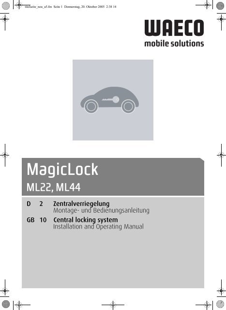
MagicLock<br />
ML<strong>22</strong>, ML<strong>44</strong><br />
D 2 Zentralverriegelung<br />
Montage- und Bedienungsanleitung<br />
GB 10<br />
UCentral locking system<br />
Installation and Operating Manual
<strong>manual</strong> <strong>ml</strong>-<strong>22</strong>/<strong>44</strong> 29.06.2004 8:32 Uhr Seite 2<br />
Inhaltsverzeichnis<br />
Hinweise zur Benutzung der Einbauanleitung . . . . . . . . . . . . . . . . . . . . . . . . . . . . . . . . . . . 2<br />
Zubehör. . . . . . . . . . . . . . . . . . . . . . . . . . . . . . . . . . . . . . . . . . . . . . . . . . . . . . . . . . . . . . . . . 2<br />
Sicherheits- und Einbauhinweise . . . . . . . . . . . . . . . . . . . . . . . . . . . . . . . . . . . . . . . . . . . 3-4<br />
Lieferumfang . . . . . . . . . . . . . . . . . . . . . . . . . . . . . . . . . . . . . . . . . . . . . . . . . . . . . . . . . . . . 4<br />
Benötigtes Werkzeug . . . . . . . . . . . . . . . . . . . . . . . . . . . . . . . . . . . . . . . . . . . . . . . . . . . . . . 5<br />
Einbau der Steuereinheiten . . . . . . . . . . . . . . . . . . . . . . . . . . . . . . . . . . . . . . . . . . . . . . . . . 6<br />
Einstellung ZV-Gestänge an das Originalgestänge . . . . . . . . . . . . . . . . . . . . . . . . . . . . . . . 7<br />
Schaltplan . . . . . . . . . . . . . . . . . . . . . . . . . . . . . . . . . . . . . . . . . . . . . . . . . . . . . . . . . . . . . . . 8<br />
Bohrschablone . . . . . . . . . . . . . . . . . . . . . . . . . . . . . . . . . . . . . . . . . . . . . . . . . . . . . . . . . . . 9<br />
Technische Daten . . . . . . . . . . . . . . . . . . . . . . . . . . . . . . . . . . . . . . . . . . . . . . . . . . . . . . . . . 9<br />
Hinweise zur Benutzung der Einbauanleitung<br />
Warnung! Sicherheitshinweis: Nichtbeachtung kann zu Personen- oder<br />
Materialschäden führen.<br />
Achtung! Sicherheitshinweis: Nichtbeachtung führt zu Materialschäden und<br />
beeinträchtigt die Funktionen der ML-<strong>22</strong>/<strong>44</strong>.<br />
◆<br />
Die Raute kennzeichnet Einbauschritte, die Sie ausführen müssen.<br />
Damit der Einbau ohne Schwierigkeiten stattfindet, diese Montage- und Bedienungsanleitung<br />
vor Beginn der Montage durchlesen.<br />
Bei einem Besitzwechsel muss diese Montage- und Bedienungsanleitung mit übergeben<br />
werden.<br />
Bei allen Arbeiten sind die entsprechenden Herstellerangaben zu beachten. Bei Fahrzeugen<br />
mit Seitenairbags in den Türen sind die entsprechenden Herstellerangaben des<br />
jeweiligen Fahrzeugherstellers zu beachten.<br />
Zubehör<br />
Produktbeschreibung<br />
Universal Schiebetürkontakt (nur in Verbindung mit ML-11 montierbar)<br />
Zentralverriegelung für eine zusätzliche Tür/Heckklappe<br />
Fahrzeugspezifische Funk-Fernbedienung<br />
Art.-Nr.<br />
ML-10<br />
ML-11<br />
MT-150-WAECO2<br />
2
<strong>manual</strong> <strong>ml</strong>-<strong>22</strong>/<strong>44</strong> 29.06.2004 8:32 Uhr Seite 3<br />
Sicherheits- und Einbauhinweise<br />
Warnung! Unzureichende<br />
Leitungsverbindungen können<br />
zur Folge haben, dass durch<br />
Kurzschluss:<br />
- Kabelbrände entstehen<br />
- der Airbag ausgelöst wird<br />
- elektronische Steuerungseinrichtungen<br />
beschädigt werden<br />
- elektrische Funktionen (Blinker, Bremslicht,<br />
Hupe, Zündung, Licht) ausfallen<br />
Beachten Sie deshalb folgende<br />
Hinweise:<br />
Bei Arbeiten an den Leitungen:<br />
30 (Eingang von Batterie Plus direkt),<br />
15 (Geschaltetes Plus, hinter Batterie)<br />
31 (Rückleitung ab Batterie, Masse)<br />
L (Blinkerleuchten Links)<br />
R (Blinkerleuchten Rechts)<br />
Die sicherste Verbindungsart ist, die<br />
Kabelenden miteinander zu verlöten<br />
und anschließend zu isolieren.<br />
Bei wiederlösbaren Verbindungen nur<br />
isolierte Kabelschuhe, Stecker und<br />
Flachsteckhülsen verwenden. Keine<br />
Quetschverbinder (Leitungsverbinder)<br />
oder Lüsterklemmen verwenden.<br />
Zum Verbinden der Kabel mit Kabelschuhen,<br />
Stecker oder Flachsteckhülsen<br />
eine Krimpzange verwenden.<br />
Warnung! Wegen Kurzschlussgefahr<br />
vor Arbeiten an der Fahrzeugelektrik<br />
immer den Minuspol<br />
der Batterie abklemmen. Bei Fahrzeugen<br />
mit Zusatzbatterie ebenfalls<br />
den Minuspol abklemmen.<br />
Achtung! Beim Abklemmen des<br />
Minuspols der Batterie verlieren<br />
alle flüchtigen Speicher der<br />
Komfort-Elektronik ihre gespeicherten<br />
Daten.<br />
Folgende Daten müssen Sie je nach Fahrzeugausstattung<br />
neu eingeben:<br />
Radiocode<br />
Fahrzeuguhr<br />
Zeitschaltuhr<br />
Bord<strong>com</strong>puter<br />
Sitzposition<br />
Hinweise zur Einstellung können Sie in der<br />
jeweiligen Bedienungsanleitung nachlesen.<br />
Warnung! Im Fahrzeug montierte<br />
Teile der MAGIC LOCK ML-<strong>22</strong>/<strong>44</strong><br />
müssen so befestigt werden, dass<br />
sie sich unter keinen Umständen<br />
(scharfes Abbremsen, Verkehrsunfall)<br />
lösen können und zu Verletzungen<br />
der Fahrzeuginsassen<br />
führen können.<br />
Bei Kabelanschlüssen an 31 (Masse):<br />
Das Kabel mit Kabelschuh und Zahnscheibe<br />
an eine fahrzeugeigene Masseschraube<br />
schrauben oder mit Kabelschuh,<br />
Blechschraube und Zahnscheibe an das<br />
Karosserieblech schrauben.<br />
Auf gute Masseübertragung achten!<br />
3
<strong>manual</strong> <strong>ml</strong>-<strong>22</strong>/<strong>44</strong> 29.06.2004 8:32 Uhr Seite 4<br />
Sicherheits- und Einbauhinweise<br />
Achtung! Zum Prüfen der Spannung<br />
in elektrischen Leitungen<br />
darf nur eine Diodenprüflampe<br />
oder ein Voltmeter benutzt werden.<br />
Prüflampen mit einem Leuchtkörper<br />
nehmen zu hohe Ströme auf und<br />
die Fahrzeugelektronik kann beschädigt<br />
werden.<br />
Prüflampe<br />
oder<br />
Voltmeter<br />
Diodenprüflampe<br />
Achtung! Um Schäden zu vermeiden, auf<br />
ausreichenden Freiraum für den Bohreraustritt<br />
achten. Jede Bohrung entgraten und mit<br />
Rostschutzmittel behandeln.<br />
Lieferumfang<br />
Für 2-türige Fahrzeuge<br />
B 2 Steuereinheiten<br />
D 1 Kabelbaum<br />
E 2 Verbindungsstangen<br />
F 2 Befestigungsklemmen<br />
G 8 Blechschrauben<br />
H 2 Lochschienen<br />
I 4 Blechmuttern<br />
J 2 Kabeldurchführungen<br />
F<br />
Für 4-türige Fahrzeuge<br />
B 2 Steuereinheiten<br />
C 2 Stelleinheiten<br />
D 1 Kabelbaum<br />
E 4 Verbindungsstangen<br />
F 4 Befestigungsklemmen<br />
G 16 Blechschrauben<br />
H 4 Lochschienen<br />
I 8 Blechmuttern<br />
J 4 Kabeldurchführungen<br />
G<br />
H<br />
I<br />
E<br />
B/C<br />
4
<strong>manual</strong> <strong>ml</strong>-<strong>22</strong>/<strong>44</strong> 29.06.2004 8:32 Uhr Seite 5<br />
Für Einbau und Montage<br />
werden benötigt:<br />
- Maßstab<br />
- Körner<br />
- Hammer<br />
- Bohrer<br />
- Bohrmaschine<br />
- Schraubendreher<br />
Benötigtes Werkzeug<br />
Schraubendrehersatz<br />
Hammer<br />
Für den elektrischen Anschluss<br />
und Überprüfung wird benötigt:<br />
- Diodenprüflampe oder Voltmeter<br />
- Krimpzange<br />
- Isolierband<br />
- Wärmeschrumpfschlauch<br />
- Heißluftföhn<br />
- Lötkolben<br />
- Lötzinn<br />
Zur Befestigung von Empfänger und<br />
Kabel benötigen Sie evtl. noch Schrauben,<br />
Blechschrauben und Kabelbinder.<br />
Bohrmaschine<br />
Bohrersatz<br />
Maßstab<br />
Körner<br />
Lötkolben<br />
Lot<br />
Krimpzange<br />
Heißluftföhn<br />
Voltmeter<br />
Diodenprüflampe<br />
oder<br />
5
<strong>manual</strong> <strong>ml</strong>-<strong>22</strong>/<strong>44</strong> 29.06.2004 8:32 Uhr Seite 6<br />
Einbau der Steuereinheiten<br />
Mechanischer Einbau<br />
Beginnen Sie mit dem Einbau an der<br />
Fahrertür. Handkurbel des Fensterhebers<br />
und Ar<strong>ml</strong>ehne abnehmen und die Türinnenverkleidung<br />
entfernen. Plastikfolie<br />
vorsichtig von unten her lösen.<br />
1.<br />
J<br />
Eine günstige Position für die Steuereinheit<br />
(B) in der Nähe der Verriegelungsstange<br />
wählen, die den Verriegelungsknopf mit<br />
dem Türschloss verbindet. Die Bewegungsrichtung<br />
von Steuereinheit und<br />
Verriegelungsstange sollte möglichst<br />
parallel und hintereinander verlaufen.<br />
2.<br />
Tür<br />
Ziehen Sie die Verbindungsstange (E)<br />
durch das Auge der Steuereinheit und<br />
biegen Sie diese so zurecht, dass sie sich<br />
proble<strong>ml</strong>os mit der Verriegelungsstange<br />
verbinden läßt.<br />
hintere Tür<br />
vordere Tür<br />
1 = verriegelt<br />
1 2 2 = entriegelt 1 2<br />
Steuereinheit mittels Bohrschablone<br />
(Seite 9) oder mit einer der beiliegenden<br />
Lochschienen (H) direkt am Türkörper<br />
befestigen.<br />
Bewegen Sie die Steuereinheit und den<br />
Verriegelungsknopf in die Position „entriegelt“<br />
und justieren Sie die Befestigungsklemmen<br />
(F) auf der Verbindungsstange (E)<br />
gemäß Abbildungen Seite 4. Den Überstand<br />
der Stange abkneifen.<br />
Achten Sie darauf, dass Fensterscheibe<br />
und Mechanismus des Fensterhebers<br />
beim Öffnen und Schließen nicht von der<br />
Steuereinheit berührt werden.<br />
3.<br />
hintere Tür<br />
1<br />
2<br />
1 = verriegelt<br />
2 = entriegelt<br />
1<br />
2<br />
vordere Tür<br />
1<br />
2<br />
Falls an der Kopfseite der Tür keine Öffnung<br />
oder Bohrung vorhanden ist, ein<br />
ca. 9 mm großes Loch bohren und die<br />
Kabelführung aus Gummi (J) einsetzen<br />
(siehe Abbildung 1).<br />
6
<strong>manual</strong> <strong>ml</strong>-<strong>22</strong>/<strong>44</strong> 29.06.2004 8:32 Uhr Seite 7<br />
Einstellung ZV-Gestänge an das Originalgestänge<br />
- Hub des Stellmotors einfahren, Originalgestänge auf „verriegeln“ stellen.<br />
- Gestänge mit Klemmblock an das Originalgestänge befestigen.<br />
Achtung! Genaue Einstellung beachten!<br />
- Beim Ver- oder Entriegeln mit dem Türschlüssel muss der Stellmotor der Zentralverriegelung<br />
auf halbem Schlüsselweg die Zentralverriegelung aktivieren (siehe Abbildung).<br />
- Gegebenenfalls die Einstellung des Betätigungsgestänges wiederholen.<br />
1/2<br />
1/2<br />
7
<strong>manual</strong> <strong>ml</strong>-<strong>22</strong>/<strong>44</strong> 29.06.2004 8:32 Uhr Seite 8<br />
Schaltplan<br />
bl = blau<br />
gr = grün<br />
br = braun<br />
w = weiß<br />
sc = schwarz<br />
ro = rot<br />
Masse<br />
GND<br />
-12 V<br />
Anschlüsse Steuerrelais<br />
1 = +12 V – rot<br />
2 = Steuerleitung ZV „zu“ – braun<br />
3 = Motorleitung ZV „auf“ – blau<br />
4 = Ext. Steuerung +12 V = ZV „auf“<br />
5 = Ext. Steuerung -12 V = ZV „auf“<br />
6 = -12 V – schwarz<br />
7 = Steuerleitung ZV „auf“ – weiß<br />
8 = Motorleitung ZV „zu“ – grün<br />
9 = Ext. Steuerung +12 V = ZV „zu“<br />
10 = Ext. Steuerung -12 V = ZV „zu“<br />
8
<strong>manual</strong> <strong>ml</strong>-<strong>22</strong>/<strong>44</strong> 29.06.2004 8:32 Uhr Seite 9<br />
Bohrschablone<br />
Bohrung Ø 5 mm<br />
Bohrung Ø 5 mm<br />
Technische Daten<br />
Betriebsspannung<br />
Stromaufnahme<br />
12 V<br />
ML-<strong>22</strong> max. 10 A<br />
ML-<strong>44</strong> max. 15 A<br />
9
<strong>manual</strong> <strong>ml</strong>-<strong>22</strong>/<strong>44</strong> 29.06.2004 8:32 Uhr Seite 12<br />
Contents<br />
Information for using the installation instructions . . . . . . . . . . . . . . . . . . . . . . . . . . . . . . . .10<br />
Accessories. . . . . . . . . . . . . . . . . . . . . . . . . . . . . . . . . . . . . . . . . . . . . . . . . . . . . . . . . . . . . 10<br />
Safety and installation instructions . . . . . . . . . . . . . . . . . . . . . . . . . . . . . . . . . . . . . . . . . . . 11<br />
Scope of delivery . . . . . . . . . . . . . . . . . . . . . . . . . . . . . . . . . . . . . . . . . . . . . . . . . . . . . . . . . 12<br />
Tools required . . . . . . . . . . . . . . . . . . . . . . . . . . . . . . . . . . . . . . . . . . . . . . . . . . . . . . . . . . . 13<br />
Installation of the control unit . . . . . . . . . . . . . . . . . . . . . . . . . . . . . . . . . . . . . . . . . . . . . . . 14<br />
Adjustment central locking rod to original rod . . . . . . . . . . . . . . . . . . . . . . . . . . . . . . . . . . . 15<br />
Wiring diagram . . . . . . . . . . . . . . . . . . . . . . . . . . . . . . . . . . . . . . . . . . . . . . . . . . . . . . . . . . 16<br />
Drill template. . . . . . . . . . . . . . . . . . . . . . . . . . . . . . . . . . . . . . . . . . . . . . . . . . . . . . . . . . . . 17<br />
Technical data. . . . . . . . . . . . . . . . . . . . . . . . . . . . . . . . . . . . . . . . . . . . . . . . . . . . . . . . . . . 17<br />
Information for using the installation instructions<br />
Warning! Safety precaution: Failure to observe this warning may result in<br />
injury to persons or damage to material.<br />
Caution! Safety precaution: Failure to observe this warning will result in<br />
damage to material and affect the proper<br />
functioning of magic lock ML-<strong>22</strong>/<strong>44</strong>.<br />
◆<br />
This symbol indicates installation steps which have to be carried out.<br />
To ensure problem-free fitting, read these installation and operating instructions carefully<br />
before starting work.<br />
When changing the owner the installation and operating instructions must be presented.<br />
Please pay attention to all according producer dates while working.<br />
For cars with side-airbags built in the seats, detection for occupied and childrenseats<br />
please take note of the corresponding information of each manufacturer.<br />
Accessories<br />
Product description<br />
Universal contact for sliding doors (can be fitted only in conjunction with ML-11)<br />
Central locking system for one additional door/tailgate<br />
Radio remote conrols for specific vehicles<br />
Ref. No.<br />
ML-10<br />
ML-11<br />
MT-150-WAECO2<br />
10
<strong>manual</strong> <strong>ml</strong>-<strong>22</strong>/<strong>44</strong> 29.06.2004 8:32 Uhr Seite 13<br />
Safety and installation instructions<br />
Warning! Improper cable<br />
connections may result in<br />
short circuits which can cause:<br />
- cable fires<br />
- triggering of the airbag<br />
- damage to electronic control equipment<br />
- failure of electrical functions (blinkers,<br />
brake lights, horn, ignition, lights).<br />
Please note the following:<br />
For working on the cables, the following<br />
terminal designations are used:<br />
30 (input from battery plus direct)<br />
15 (switched plus, behind battery)<br />
31 (return cable from battery, neutral)<br />
L Blinker left<br />
R Blinker right<br />
The securest form of connection is by<br />
soldering the cable ends and then<br />
insulating the connection.<br />
For releasable connections, use only<br />
insulated cable brackets, connector<br />
plugs and tabs. Do not use lustre<br />
terminals. For connecting the cables<br />
with cable brackets, plugs or tabs,<br />
use crimping pliers.<br />
For cable connections to 31 (earth):<br />
Attach the cable with a bracket and<br />
toothed washer to an earthing screw on<br />
the vehicle or screw it onto the metalwork<br />
of the vehicle using a bracket, metal screw<br />
and toothed washer.<br />
Always ensure a good earthing connection!<br />
Warning! Because of the risk of<br />
short circuits, always disconnect<br />
the negative pole of the battery<br />
before starting work. At vehicles<br />
with a supplementary battery, also<br />
disconnect this negative pole.<br />
Caution! On disconnecting the<br />
negative pole of the battery, all<br />
the volatile memories of the<br />
convenience electronics will<br />
lose their stored data.<br />
Depending on the vehicle’s equipment,<br />
the following date may have to be<br />
reprogrammed:<br />
Radio code<br />
Clock<br />
Timer<br />
Board <strong>com</strong>puter<br />
Seat position<br />
Instructions on how to reset these can<br />
be found in the relevant operating<br />
instructions.<br />
Warning! The <strong>com</strong>ponents of<br />
the MAGIC LOCK ML-<strong>22</strong>/<strong>44</strong><br />
which are inside the vehicle must<br />
be securely fixed so that they<br />
cannot <strong>com</strong>e loose and injure<br />
the vehicle’s occupants under<br />
any circumstances (emergency<br />
braking, traffic accident).<br />
11
<strong>manual</strong> <strong>ml</strong>-<strong>22</strong>/<strong>44</strong> 29.06.2004 8:32 Uhr Seite 14<br />
Safety and installation instructions<br />
Caution! To check the voltage in<br />
electric cables, use only a diode<br />
test lamp or a voltmeter. Test<br />
lamps which light up take too<br />
much current and the vehicle<br />
electronics may be damaged.<br />
Testlamp<br />
or<br />
Diode testlamp<br />
Voltmeter<br />
Caution! To avoid damage, always ensure<br />
that there is enough clearance for the drill bit<br />
to emerge. Every drill hole must be deburred<br />
and treated with a rust proofing agent.<br />
Scope of delivery<br />
For 2-door vehicles<br />
B 2 Control units<br />
D 1 Cable harness<br />
E 2 Connecting rods<br />
F 2 Fastening clips<br />
G 8 Sheet metal screws<br />
H 2 Rails with punched holes<br />
I 4 Fastening nuts<br />
J 2 Cable conducts<br />
F<br />
For 4-door vehicles<br />
B 2 Control units<br />
C 2 Servo units<br />
D 1 Cable harness<br />
E 4 Connecting rods<br />
F 4 Fastening clips<br />
G 16 Sheet metal screws<br />
H 4 Rails with punched holes<br />
I 8 Fastening nuts<br />
J 4 Cable conducts<br />
G<br />
H<br />
I<br />
E<br />
B/C<br />
12
<strong>manual</strong> <strong>ml</strong>-<strong>22</strong>/<strong>44</strong> 29.06.2004 8:32 Uhr Seite 15<br />
The following are required<br />
for installation:<br />
- Measure<br />
- Prick punch<br />
- Hammer<br />
- Drill bits<br />
- Drill<br />
- Screwdrivers<br />
Tools required<br />
Set of screwdrivers<br />
Hammer<br />
The following are required for the<br />
electrical connections and testing:<br />
- Diode test lamp or voltmeter<br />
- Crimping pliers<br />
- Insulation tape<br />
- Heat shrinkable tubing<br />
- Hot blow drier<br />
- Soldering iron<br />
- Solder<br />
For securing the receiver and<br />
cables, you may also need bolts,<br />
metal screws and cable binders.<br />
Drill<br />
Set of drill<br />
bits<br />
Measure<br />
Prick<br />
punch<br />
Soldering<br />
iron<br />
Solder<br />
Hot<br />
blow dri-<br />
Crimping<br />
pliers<br />
Voltmeter<br />
Diode testlamp<br />
or<br />
13
<strong>manual</strong> <strong>ml</strong>-<strong>22</strong>/<strong>44</strong> 29.06.2004 8:32 Uhr Seite 16<br />
Installation of the control unit<br />
Mechanical installation<br />
Commence installation on the driver’s<br />
door. Remove the crank handle of the<br />
window winder and the arm rest and<br />
remove the inside panelling of the door.<br />
Remove the plastic foil carefully from<br />
the bottom.<br />
1.<br />
J<br />
Choose a favourable position for the<br />
control unit (B) close to the locking rod<br />
which connects the locking button to the<br />
door lock. The direction of movement of<br />
the control unit and the locking rod should<br />
be as parallel as possible and in tandem.<br />
Pull the connecting rod (E) through the<br />
eye of the control unit and bend it so<br />
as to provide easy connection with the<br />
locking bar.<br />
2.<br />
rear door<br />
door<br />
front door<br />
1 = locked<br />
1 2 2 = unlocked 1 2<br />
Attach the control unit directly to the door<br />
by means of a drill template (page 9) or<br />
one of the enclosed rails with punched<br />
holes (H). Move the control unit and the<br />
locking button into ”unlocked” position<br />
and adjust the fastening clips (F) on the<br />
connecting rod (E) according figures on<br />
page 4 and pinch off the excess part of<br />
the rod.<br />
3.<br />
rear door<br />
1<br />
2<br />
1 = locked<br />
1<br />
2<br />
front door<br />
Pay attention that the window pane and<br />
the winder mechanism do not <strong>com</strong>e<br />
in contact with the control unit during<br />
opening and closing.<br />
2 = unlocked<br />
1<br />
2<br />
If the head of the door has no hole or<br />
opening in it, drill a hole with approx. 9 mm<br />
diameter and insert the rubber cable.<br />
14
<strong>manual</strong> <strong>ml</strong>-<strong>22</strong>/<strong>44</strong> 29.06.2004 8:32 Uhr Seite 17<br />
Adjustment central locking rod to original rod<br />
- Retract the lifting part of the servomotor, position the original rod to ”lock”.<br />
- Fasten the rod to the original rod by means of a clamp.<br />
Attention! Pay attention to a precise setting<br />
- When the door is locked or unlocked with the door key, the servomotor should actuate<br />
the central locking system at half course of the key (see diagram).<br />
- Repeat the setting of the connecting rod if necessary.<br />
1/2<br />
1/2<br />
15
<strong>manual</strong> <strong>ml</strong>-<strong>22</strong>/<strong>44</strong> 29.06.2004 8:32 Uhr Seite 18<br />
Wiring diagram<br />
bl = blue<br />
gr = gree<br />
br = brown<br />
w = white<br />
sc = black<br />
ro = red<br />
Masse<br />
GND<br />
-12 V<br />
16<br />
Electrical connection external control<br />
1 = +12 V – red<br />
2 = control cable CL ”close” – brown<br />
3 = motor cable CL ”open” – blue<br />
4 = exeternal control +12 V = ZV ”open”<br />
5 = exeternal control GND (-) = ZV ”open”<br />
6 = GND – black<br />
7 = control cable CL ”close” – withe<br />
8 = motor cable CL ”close” – green<br />
9 = exeternal control +12 V = ZV ”close”<br />
10 = exeternal control GND (-) = ZV ”close”
<strong>manual</strong> <strong>ml</strong>-<strong>22</strong>/<strong>44</strong> 29.06.2004 8:32 Uhr Seite 19<br />
Drill template<br />
hole Ø 5 mm<br />
hole Ø 5 mm<br />
Technical data<br />
Operating voltage<br />
Input current<br />
12 V<br />
ML-<strong>22</strong> max. 10 A<br />
ML-<strong>44</strong> max. 15 A<br />
17
<strong>manual</strong> <strong>ml</strong>-<strong>22</strong>/<strong>44</strong> 29.06.2004 8:32 Uhr Seite 19
<strong>manual</strong> <strong>ml</strong>-<strong>22</strong>/<strong>44</strong> 29.06.2004 8:32 Uhr Seite 19
adresse_A5_05.fm Seite 2 Mittwoch, 21. September 2005 3:46 15<br />
Headquarters<br />
D<br />
WAECO International GmbH · Hollefeldstraße 63 · D-48282 Emsdetten<br />
Fon: +49 2572 879-195 · Fax: +49 2572 879-3<strong>22</strong> · E-Mail: info@waeco.de · Internet: www.waeco.de<br />
Europe<br />
CH<br />
WAECO Schweiz AG<br />
Riedackerstrasse 7a<br />
CH-8153 Rü<strong>ml</strong>ang (Zürich)<br />
Fon: +41 <strong>44</strong> 8187171<br />
Fax: +41 <strong>44</strong> 8187191<br />
E-Mail: info@waeco.ch<br />
I<br />
WAECO Italcold SRL<br />
Via dell’Industria 4/0<br />
I-40012 Calderara di Reno (BO)<br />
Fon: +39 051 727094<br />
Fax: +39 051 727687<br />
E-Mail: sales@waeco.it<br />
Overseas + Middle East<br />
AUS<br />
WAECO Pacific Pty. Ltd.<br />
1 John Duncan Court<br />
Varsity Lakes QLD 4<strong>22</strong>7<br />
Fon: +61 7 55076000<br />
Fax: +61 7 55<strong>22</strong>1003<br />
E-Mail: sales@waeco.<strong>com</strong>.au<br />
DK<br />
E<br />
F<br />
FIN<br />
WAECO Danmark A/S<br />
Tværvej 2<br />
DK-6640 Lunderskov<br />
Fon: +45 75585966<br />
Fax: +45 75586307<br />
E-Mail: waeco@waeco.dk<br />
WAECO Ibérica S.A.<br />
Camí del Mig, 106<br />
Poligono Industrial Les Corts<br />
E-08349 Cabrera de Mar<br />
(Barcelona)<br />
Fon: +34 93 750<strong>22</strong>77<br />
Fax: +34 93 7500552<br />
E-Mail: info@waeco.es<br />
WAECO Distribution SARL<br />
ZAC 2 · Les Portes de L‘Oise<br />
Rue Isaac Newton – BP 59<br />
F-60230 Chambly (France)<br />
Fon: +33 1 30282020<br />
Fax: +33 1 30282010<br />
E-Mail: info@waeco.fr<br />
WAECO Finland OY<br />
Mestarintie 4<br />
FIN-01730 Vantaa<br />
Fon: +358 20 7413<strong>22</strong>0<br />
Fax: +358 9 7593700<br />
E-Mail: waeco@waeco.fi<br />
www.waeco.<strong>com</strong><br />
N<br />
NL<br />
S<br />
UK<br />
WAECO Norge AS<br />
Leif Weldingsvei 16<br />
N-3208 Sandefjord<br />
Fon: +47 33428450<br />
Fax: +47 33428459<br />
E-Mail: firmapost@waeco.no<br />
WAECO Benelux B.V.<br />
Ecustraat 3<br />
NL-4879 NP Etten-Leur<br />
Fon: +31 76 5029000<br />
Fax: +31 76 5029090<br />
E-Mail: verkoop@waeco.nl<br />
WAECO Svenska AB<br />
Gustaf Melins gata 7<br />
S-42131 Västra Frölunda<br />
(Göteborg)<br />
Fon: +46 31 7341100<br />
Fax: +46 31 7341101<br />
E-Mail: info@waeco.se<br />
WAECO UK Ltd.<br />
Dorset DT2 8LY · Unit G<br />
Roman Hill Business Park<br />
UK-Broadmayne<br />
Fon: +<strong>44</strong> 1305 854000<br />
Fax: +<strong>44</strong> 1305 854288<br />
E-Mail: sales@waeco.co.uk<br />
HK<br />
WAECO Impex Ltd.<br />
Headquarters<br />
Suites 3210-12 · 32/F · Tower 2<br />
The Gateway · 25 Canton Road<br />
Tsim Sha Tsui · Kowloon<br />
Hong Kong<br />
Fon: +852 2 4632750<br />
Fax: +8 52 24639067<br />
E-Mail: info@waeco.<strong>com</strong>.hk<br />
ROC WAECO Impex Ltd.<br />
Taipei Office<br />
2 FL-3 · No. 56 Tunhua South Rd, Sec 2<br />
Taipei 106, Taiwan<br />
Fon: +886 2 27014090<br />
Fax: +886 2 27060119<br />
E-Mail: marketing@waeco.<strong>com</strong>.tw<br />
UAE<br />
USA<br />
WAECO Middle East FZCO<br />
R/A 8, SD 6<br />
Jebel Ali, Dubai<br />
Fon: +971 4 8833858<br />
Fax: +971 4 8833868<br />
E-Mail: waeco@emirates.net.ae<br />
WAECO USA, Inc.<br />
8 Heritage Park Road<br />
Clinton, CT 06413<br />
Fon: +1 860 66<strong>44</strong>911<br />
Fax: +1 860 66<strong>44</strong>912<br />
E-Mail: customercare@waecousa.<strong>com</strong><br />
<strong>44</strong>45100036 10/2005