CONTI® SYNCHRODRIVE Zahnriemen ... - ContiTech AG
CONTI® SYNCHRODRIVE Zahnriemen ... - ContiTech AG
CONTI® SYNCHRODRIVE Zahnriemen ... - ContiTech AG

Sie wollen auch ein ePaper? Erhöhen Sie die Reichweite Ihrer Titel.
YUMPU macht aus Druck-PDFs automatisch weboptimierte ePaper, die Google liebt.
Power Transmission Group<br />
CONTI ®<br />
<strong>SYNCHRODRIVE</strong><br />
<strong>Zahnriemen</strong><br />
Synchronous Drive Belts
CONTI ®<br />
<strong>SYNCHRODRIVE</strong><br />
<strong>Zahnriemen</strong> Synchronous Drive Belts<br />
Inhalt Contents<br />
1 Produktbeschreibung Product description 3 – 10<br />
Eigenschaften Properties 4 – 5<br />
Ausführungen und Aufbau Versions and construction 6<br />
Bezeichnung Designation 7<br />
Lieferprogramm Product range 8 – 9<br />
Toleranzen Tolerances 10<br />
2 Zahnscheiben Pulleys 11 – 20<br />
Bezeichnung Designation 12 – 13<br />
Mindest-Zähnezahl Minimum number of teeth 14<br />
Scheibendurchmesser Pulley diameters 15 – 20<br />
Toleranzen Tolerances 21<br />
Spannplatten Clamp plates 22<br />
3<br />
Berechnung von<br />
<strong>Zahnriemen</strong>antrieben<br />
Calculation of<br />
Timing Belt Drives<br />
23 – 46<br />
Formelzeichen,<br />
Einheiten und Begriffe<br />
Glossary of symbols,<br />
units and terms<br />
24 – 25<br />
Berechnungsunterlagen Calculation documentation 26 – 37<br />
Berechnungsbeispiel<br />
Hubantrieb<br />
Examples of design procedure<br />
steps: Lifting drive<br />
38 – 41<br />
Berechnungsbeispiel<br />
Linearantrieb<br />
Examples of design procedure<br />
steps: Linear drive<br />
42 – 45<br />
Vorspannungsmessgeräte Pretension gauges 46<br />
4 Stichwortverzeichnis Index 47– 51
1 Produktbeschreibung<br />
Product description<br />
Eigenschaften<br />
Ausführungen und Aufbau<br />
Bezeichnung<br />
Lieferprogramm<br />
Toleranzen<br />
Properties<br />
Versions and construction<br />
Designation<br />
Product range<br />
Tolerances<br />
3
1 Produktbeschreibung / Product description<br />
Eigenschaften Properties<br />
CONTI ® <strong>SYNCHRODRIVE</strong> <strong>Zahnriemen</strong> für synchrone<br />
Übertragung von Dreh- und Linearbewegungen<br />
CONTI ® <strong>SYNCHRODRIVE</strong> <strong>Zahnriemen</strong> sind Antriebselemente<br />
aus hochbeanspruchbarem Polyurethan-<br />
Elastomer mit Stahlcordzugträgern. Sie werden nach<br />
einem speziell entwickelten Produktionsverfahren mit<br />
hoher Präzision in endlicher Länge gefertigt.<br />
CONTI ® <strong>SYNCHRODRIVE</strong> <strong>Zahnriemen</strong> werden in endlicher<br />
Ausführung oder auch endlos verschweißt eingesetzt.<br />
In allen Fällen übertragen sie Drehbewegungen<br />
winkelgenau und gleichförmig. CONTI ® <strong>SYNCHRODRIVE</strong><br />
<strong>Zahnriemen</strong> ermöglichen wirtschaftliche Antriebslösungen<br />
auch bei schwierigen Bedingungen. Ihre Eigenschaften<br />
ergeben funktionsgerechte Antriebslösungen mit<br />
großer Betriebssicherheit und Wartungsfreiheit.<br />
CONTI ® <strong>SYNCHRODRIVE</strong> <strong>Zahnriemen</strong> werden in zehn<br />
Zahnprofilen und mehreren Standardbreiten gefertigt.<br />
Damit decken sie weite Einsatzgebiete mit unterschiedlichsten<br />
Belastungen und Bedingungen ab. Beispielhafte<br />
Anwendungen sind Antriebe mit großen Achsabständen,<br />
synchrone Fördersysteme und Transportvorrichtungen<br />
mit Gleitschienen und Positionier- und Reversierantriebe<br />
in der Linear- und Steuertechnik. Moderne Fertigungsverfahren<br />
und Qualitätsprüfungen in allen Verarbeitungsstufen<br />
gewährleisten Produkte größter Zuverlässigkeit<br />
mit gleichbleibend hohem Qualitätsstandard.<br />
CONTI ® <strong>SYNCHRODRIVE</strong> Belts for synchronous<br />
transmission of rotary and linear motion.<br />
CONTI ® <strong>SYNCHRODRIVE</strong> belts are power transmission<br />
products made from a highly durable polyurethane<br />
elastomer incorporating a steel-cord tension member.<br />
They are manufactured precisely to length using a newly<br />
developed production technique.<br />
CONTI ® <strong>SYNCHRODRIVE</strong> belts can be used in the<br />
openended or endless form. In all cases, they ensure<br />
that rotary motion is transmitted uniformly and with<br />
angular precision. CONTI ® <strong>SYNCHRODRIVE</strong> belts permit<br />
low-cost drive designs, even where difficult operating<br />
conditions have to be taken into account. Their properties<br />
provide a highly reliable, maintenance-free solution to<br />
even the most demanding drive problems.<br />
CONTI ® <strong>SYNCHRODRIVE</strong> belts are available in ten tooth<br />
profiles and several standard widths, covering a host of<br />
different applications involving various loads and service<br />
conditions. They are ideal for drives with a large centre<br />
distance, for synchronous conveyor systems and transport<br />
devices with sliding rails as well as for positioning<br />
and reversing drives in linear and control engineering.<br />
Modern production techniques and rigorous in-process<br />
quality controls guarantee products with maximum<br />
reliability and a consistently high standard of quality.<br />
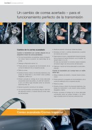
Exakte Synchronität<br />
durch formschlüssiges Antriebssystem<br />
Wie bei einem Zahnradantrieb greifen die Zähne<br />
des Riemens direkt in die Verzahnung der Antriebsscheiben.<br />
Das formschlüssige Antriebsprinzip ergibt<br />
den synchronen Lauf und eine jederzeit konstante<br />
Umfangsgeschwindigkeit.<br />
Precise synchronism<br />
due to positive engagement<br />
The belt teeth mesh with those of the pulley in the same<br />
manner as the teeth on a gear. This positive drive principle<br />
provides synchronous operation and eliminates<br />
speed variation.<br />
Vielseitige Anwendungsmöglichkeiten bei geringem<br />
konstruktivem Aufwand<br />
CONTI ® <strong>SYNCHRODRIVE</strong> <strong>Zahnriemen</strong> können in endlicher<br />
oder endloser Ausführung als synchrone Antriebsoder<br />
Transportriemen eingesetzt werden. Für besondere<br />
Anwendungen lassen sich CONTI ® <strong>SYNCHRODRIVE</strong><br />
<strong>Zahnriemen</strong> auch mit Steuer- oder Transportnocken<br />
aus Thermoplasten hochbeanspruchbar verschweißen.<br />
Als endliche Antriebselemente eignen sich<br />
CONTI ® <strong>SYNCHRODRIVE</strong> <strong>Zahnriemen</strong> hervorragend für<br />
Linear-und Steuerantriebe, um Drehbewegungen positionier-<br />
und wiederholgenau umzusetzen.<br />
A variety of possible applications<br />
at low design cost<br />
CONTI ® <strong>SYNCHRODRIVE</strong> belts can be used as<br />
synchronous drive or transport belts in either the<br />
open-ended or endless version. For special applications,<br />
CONTI ® <strong>SYNCHRODRIVE</strong> belts can have heavy-duty<br />
profiles welded to them for indexing and conveying<br />
applications. As open-ended drive components,<br />
CONTI ® <strong>SYNCHRODRIVE</strong> belts are ideal for linear and<br />
control drives that have to transmit rotary motion with<br />
repeat accuracy and multiple positioning control.<br />
4
Geringe Wellen- und Lagerbelastung<br />
Das Verzahnungsprinzip erfordert nur eine geringe <strong>Zahnriemen</strong>vorspannung.<br />
Die Wellen- und Lagerbelastungen<br />
bleiben gering.<br />
Low loads on shafts and bearings<br />
The tooth grip principle requires only low initial belt<br />
tensioning. Thus the load on shafts and bearings is kept<br />
to a minimum.<br />
Geringer Raumbedarf<br />
Die hohe dynamische Belastbarkeit und Flexibilität<br />
er-möglichen die Anwendung kleiner Synchronscheibendurchmesser<br />
und kurzer Wellenabstände sowie die<br />
Anordnung von Rückenspannrollen. Damit können<br />
wirtschaftliche Antriebe mit kleinem Bauvolumen und<br />
geringem Gewicht konstruiert werden.<br />
Compact drive design<br />
High dynamic stability and flexibility allows the use<br />
of small pulley diameters, low centre distances, and<br />
belt-back idlers. This enables a lightweight, low-cost<br />
drive setup with less space requirement.<br />
Kein Wartungsaufwand<br />
CONTI ® <strong>SYNCHRODRIVE</strong> <strong>Zahnriemen</strong> sind wartungsfrei.<br />
Schmieren und Nachspannen sind nicht erforderlich.<br />
Durch die Verwendung von Stahlcordzugträgern<br />
hoher Festigkeit ist nach einer kurzen Einlaufphase eine<br />
konstante Riemenspannung gewährleistet.<br />
No maintenance<br />
CONTI ® <strong>SYNCHRODRIVE</strong> belts are maintenance-free;<br />
no lubrication or retensioning is required. Constant belt<br />
tension is guaranteed by the use of a high-strength<br />
steel-cord tension member.<br />
Hoher Wirkungsgrad<br />
Die flexible und biegetüchtige <strong>Zahnriemen</strong>ausführung<br />
sowie die gute maßliche Abstimmung der Zahnkontur von<br />
Riemen und Synchronscheiben ermöglichen Antriebe mit<br />
einem Wirkungsgrad von 98 %.<br />
High efficiency<br />
The superb flexural properties of the synchronous drive<br />
belt as well as the exact dimensional mating of the belt<br />
and pulley tooth contours permit drives with an efficiency<br />
of 98 %.<br />
CONTI ® <strong>SYNCHRODRIVE</strong> <strong>Zahnriemen</strong> sind<br />
abriebfest<br />
öl- und fettbeständig<br />
benzin- und benzolbeständig<br />
hydrolysebeständig<br />
UV- und ozonbeständig<br />
temperaturbeständig von –30 °C bis 80 °C<br />
(bitte fordern Sie im Bereich unter –10 °C und<br />
über 50 °C technische Beratung an)<br />
verschweißbar mit Thermoplasten<br />
CONTI ® <strong>SYNCHRODRIVE</strong> belts are resistant to<br />
wear<br />
oil and grease<br />
petrol and benzene<br />
hydrolysis<br />
UV and ozone<br />
temperatures ranging from –30 °C bis 80 °C<br />
(for operational temperatures outside –10 °C<br />
to 50 °C please seek advice from our technical<br />
experts)<br />
can be bonded to thermoplastics<br />
5
1 Produktbeschreibung / Product description<br />
Ausführungen und Aufbau Versions and construction<br />
HF flexible Ausführung, alle Profile außer 3 mm<br />
Teilung, z. B. für Antriebe mit kleinen Scheiben.<br />
HP verstärkte Ausführung Profile HTD und STD,<br />
z. B. für Steuerungssysteme mit hoher Belastung.<br />
HS hohe Zugträgersteifigkeit Profile HTD und STD,<br />
z. B. für hochpräzise Linearantriebe.<br />
XHP extra hohe Zugfestigkeit Profil HTD 14M,<br />
z. B. für Hubsysteme.<br />
PAZ Gewebearmierung auf der Zahnseite, z. B. für<br />
Transportvorrichtungen mit Gleitschienen.<br />
Antistatische Ausführung aPAZ auf Anfrage.<br />
PAR Gewebearmierung auf dem Riemenrücken,<br />
z. B. für Stauförderer.<br />
Antistatische Ausführung aPAR auf Anfrage.<br />
V endlos verschweißte <strong>Zahnriemen</strong> in Ausführung<br />
HF und Längen ab 1000 mm, alle Profile außer<br />
3 mm Teilung, z. B. für Rotationsantriebe mit<br />
großen Achsabständen.<br />
Weitere Sonderausführungen auf Anfrage,<br />
z. B. Aramid-Zugträger.<br />
HF<br />
HP<br />
HS<br />
XHP<br />
PAZ<br />
PAR<br />
V<br />
high flexibility version all profiles except for 3 mm<br />
pitch e.g. for drives with small pulley diameters.<br />
high power reinforced version HTD and STD<br />
profiles, e.g. for heavy-duty control systems.<br />
high stiffness of tension member HTD and STD<br />
profiles, e.g. for high-precision linear drives.<br />
extremely high power tensile-strength HTD 14M<br />
profile, e.g. for lifting systems.<br />
with polyamide fabric facing on the teeth side<br />
e.g. for sliding-rail transport systems.<br />
Antistatic aPAZ version on request.<br />
with polyamide fabric facing on the back of the<br />
belt e.g. for skid-queuing conveyors.<br />
Antistatic aPAR version on request.<br />
endless belt in HF version and lengths from<br />
1000 mm, all profiles except for 3 mm pitch<br />
e.g. for rotary drives with large center<br />
distances.<br />
Other special versions can be supplied on request,<br />
e.g. aramide tension member.<br />
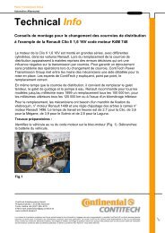
Aufbau<br />
Construction<br />
Polyurethan-Riemenrücken<br />
Stahlcordzugträger<br />
Polyurethan-Zähne<br />
Optional:<br />
Gewebearmierung<br />
zahn-/rückenseitig<br />
Polyurethane belt back<br />
Steel-cord tension member<br />
Polyurethane teeth<br />
Optional:<br />
Fabric facing in the pulley<br />
side/back of the belt<br />
Die Elemente des <strong>Zahnriemen</strong>s sind:<br />
Polyurethan-Zähne und -Riemenrücken,<br />
Farbe: schwarz<br />
Stahlcordzugträger, Schlagrichtungen zueinander<br />
balanciert<br />
Our synchronous drive belts are made up of:<br />
polyurethane teeth and back,<br />
color: black<br />
steel-cord tension member, with balanced right/lefthanded<br />
cord twist<br />
Polyurethan-Zähne und -Riemenrücken<br />
Hochbeanspruchbares Polyurethan-Elastomer bildet<br />
Zähne und Riemenrücken mit einer hervorragenden<br />
Bindung zum Zugträger. Die hohe Abriebfestigkeit des<br />
Polyurethans ist die Voraussetzung für störungsfreien<br />
Antrieb und lange Lebensdauer. Dieses wird unterstützt<br />
durch die balancierte Zugträgeranordnung.<br />
Polyurethane teeth and back<br />
Belt teeth and back are made from a tough polyurethane<br />
elastomer with excellent adhesion to the tension<br />
member. The high wear resistance of the polyurethane<br />
ensures trouble-free drive performance and a long<br />
service life. These features are enhanced even more<br />
by the balanced layout of the tension cords.<br />
Stahlcordzugträger<br />
<strong>Zahnriemen</strong> für formschlüssige Antriebssysteme erfordern<br />
eine hohe Längenkonstanz und Zugfestigkeit.<br />
Kantenparallel angeordnete Stahlcordzugträger hoher<br />
Festigkeit gewährleisten große Belastbarkeit der <strong>Zahnriemen</strong><br />
und exaktes Laufverhalten.<br />
Steel-cord tension member<br />
Synchronous drive belts for positive drive systems must<br />
have a high resistance to elongation and a high tensile<br />
strength. Extra-strong steel tension cords, laid parallel to<br />
the belt edges, guarantee the belt’s high loading capacity<br />
and accurate running properties.<br />
6
Bezeichnung Designation<br />
CONTI ® <strong>SYNCHRODRIVE</strong> <strong>Zahnriemen</strong> werden nach<br />
den für die unterschiedlichen Riementypen festgelegten<br />
Standards mit Wirklänge, Zahnteilung und<br />
<strong>Zahnriemen</strong>breite bezeichnet, ergänzt durch Kurzzeichen<br />
für die Ausführung, siehe Seite 4.<br />
CONTI ® <strong>SYNCHRODRIVE</strong> synchronous drive belts are<br />
specified in accordance with defined standards for the<br />
different belt types showing the pitch length, tooth pitch<br />
and belt width, plus a code for the belt version, see<br />
page 4.<br />
Wirklänge in m<br />
Die Wirklänge des <strong>Zahnriemen</strong>s ist der Gesamtumfang,<br />
gemessen auf der biegeneutralen Wirklinie.<br />
Die Wirklänge liegt in der Mitte des Zugträgers.<br />
Pitch length in m<br />
The pitch length of the belt is the overall circum ference,<br />
or length measured at the neutral pitch line. The pitch<br />
length is located in the middle of the tension member.<br />
Zahnteilung in mm<br />
Die Zahnteilung ist der lineare Abstand zwischen zwei<br />
benachbarten Zähnen in Höhe der Wirklinie.<br />
Tooth pitch in mm<br />
The tooth pitch is the linear distance between two<br />
adjacent teeth at the pitch line.<br />
<strong>Zahnriemen</strong>breite in mm<br />
Die <strong>Zahnriemen</strong>breite und die Breitenbezeichnung<br />
sind identisch.<br />
Belt width in mm<br />
The belt width and width designation are identical.<br />
Beispiele<br />
Examples<br />
CONTI ® Synchrodrive HTD <strong>Zahnriemen</strong>/ Synchronous drive belts – M 30 - 8M - 50 HP<br />
M endliche Ausführung open-ended type<br />
30 30 m Wirklänge pitch length 30 m<br />
8M 8 mm Zahnteilung, HTD Profil tooth pitch 8 mm, HTD profile<br />
50 50 mm <strong>Zahnriemen</strong>breite belt width 50 mm<br />
HP verstärkte Ausführung reinforced version<br />
CONTI ® Synchrodrive STD <strong>Zahnriemen</strong>/ Synchronous drive belts – V 2400 - S 5M - 30 HF<br />
V endlos verschweißte Ausführung endless type<br />
2400 2400 mm Riemenlänge belt length 2400 mm<br />
S 5M 5 mm Zahnteilung, STD Profil tooth pitch 5 mm, STD profile<br />
30 30 mm <strong>Zahnriemen</strong>breite belt width 30 mm<br />
HF flexible Ausführung flexible version<br />
CONTI ® Synchrodrive <strong>Zahnriemen</strong>/ Synchronous drive belts – 10 x M 30 H 100 PAZ<br />
10 Anzahl der Rollen number of rolls<br />
M endliche Ausführung open-ended type<br />
30 30 m Wirklänge pitch length 30 m<br />
H 0,5 Inch = 12,7 mm Zahnteilung tooth pitch 0.5 Inch = 12.7 mm<br />
100 1,0 Inch = 25,4 mm <strong>Zahnriemen</strong>breite belt width 1.0 Inch = 25.4 mm<br />
PAZ Laufseite mit Gewebearmierung with fabric facing on the pulley side<br />
Die Zähnezahl ergibt sich aus der Wirklänge und Teilung:<br />
The number of teeth is a function of pitch length and pitch:<br />
z = L w<br />
t<br />
7
1 Produktbeschreibung / Product description<br />
Lieferprogramm Product range<br />
Profile<br />
CONTI ® <strong>SYNCHRODRIVE</strong> <strong>Zahnriemen</strong> werden in 10 Profilgrößen<br />
gefertigt. Die Maße der HTD- und STD-<br />
<strong>Zahnriemen</strong> entsprechen dem Entwurf ISO/F DIS 13050.<br />
In Tabelle 1 (Seite 9) sind die Profilmaße und weitere<br />
technische Angaben der lieferbaren <strong>Zahnriemen</strong> zusammengefasst.<br />
Bei Linearantrieben mit besonders hohen<br />
Genauigkeitsanforderungen ist die Verwendung von<br />
Sonder-Synchronscheiben erforderlich. Weitere Angaben<br />
zu den Scheiben enthält das Kapitel „Zahnscheiben“,<br />
beginnend auf Seite 11.<br />
Profiles<br />
CONTI ® <strong>SYNCHRODRIVE</strong> synchronous drive belts are<br />
manufactured in 10 profile sizes. Dimensions of HTD<br />
and STD synchronous drive belts correspond to the<br />
specifications laid down in ISO/F DIS 13050 (draft version).<br />
Table 1 on page 9 gives a summary of the profile<br />
dimensions as well as other technical information for the<br />
belts we supply. Special pulleys must be used for linear<br />
drives with high precision requirements. More information<br />
about pulleys is given in section 2 on “Pulleys” which<br />
starts on page 11.<br />
Längen<br />
CONTI ® <strong>SYNCHRODRIVE</strong> <strong>Zahnriemen</strong> können in endlicher<br />
oder endloser Ausführung eingesetzt werden.<br />
Lengths<br />
CONTI ® <strong>SYNCHRODRIVE</strong> synchronous drive belts are<br />
available in either the open-ended or endless version.<br />
Breiten<br />
CONTI ® <strong>SYNCHRODRIVE</strong> <strong>Zahnriemen</strong> werden in mehreren<br />
Standardbreiten geliefert. Die Maße sind in Tabelle 2<br />
(Seite 9) aufgeführt.<br />
Abweichende Breiten auf Anfrage.<br />
Widths<br />
CONTI ® <strong>SYNCHRODRIVE</strong> synchronous drive belts are<br />
supplied in several standard widths. Dimensions are<br />
given in Table 2 on page 9. Other widths are available<br />
on request.<br />
Ausführungen<br />
CONTI ® <strong>SYNCHRODRIVE</strong> <strong>Zahnriemen</strong> aus Polyurethan<br />
mit kantenparallel angeordnetem Stahlcordzuträger sind<br />
Präzisionselemente für Anwendungen im Bereich der<br />
Antriebs- und Transporttechnik. Für spezielle Anforderungen<br />
sind <strong>Zahnriemen</strong> in unterschiedlichen Ausführungen<br />
lieferbar. Erläuterungen siehe Abschnitt „Eigenschaften”,<br />
Seite 4 und 5.<br />
Versions<br />
CONTI ® <strong>SYNCHRODRIVE</strong> synchronous drive belts made<br />
from polyurethane with steel cords aligned parallel to the<br />
belt edges are precision-made components for applications<br />
in drive and transportation engineering. Several<br />
versions are available to meet various operating requirements.<br />
More details are given on page 4 and 5 under<br />
“Properties”.<br />
Abb. Fig. 1<br />
HTD<br />
STD<br />
Zahnprofil Tooth profile<br />
HTD 3M, HTD 5M, HTD 8M, HTD 14M<br />
Zahnprofil Tooth profile<br />
STD S 5M, STD S 8M, STD S 3M*<br />
*auf Anfrage on request<br />
XL, L, H<br />
Zahnprofil Tooth profile<br />
XL, L, H<br />
8
Kenndaten / Specifications<br />
Tab. 1<br />
Zahnprofil Tooth Profile HTD STD Trapez<br />
3M 5M 8M 14M S 3M S 5M S 8M XL L H<br />
Zahnteilung t Tooth pitch t mm 3,00 5,00 8,00 14,00 3,00 5,00 8,00 5,08 9,525 12,70<br />
Inch 0,20 0,375 0,50<br />
Riemendicke h s Belt thickness h s mm 2,40 3,60 5,60 10,00 2,30 3,40 5,20 2,30 3,60 4,30<br />
Zahnhöhe h t Tooth heigth h t mm 1,30 2,10 3,40 6,10 1,14 1,90 3,00 1,27 1,91 2,29<br />
Gewicht m spez pro<br />
mm Riemenbreite<br />
Ausführung:<br />
Weight m spez per<br />
mm of belt width<br />
Type:<br />
HF HF 10 –3 kg/m 3,36 5,40 10,37 3,21 5,24 2,16 3,650 4,53<br />
HP HP 10 –3 kg/m 3,15 4,06 6,32 11,27 3,08 3,91 6,22<br />
HS HS 10 –3 kg/m 4,70 7,22 11,40 4,64 7,12<br />
XHP XHP 10 –3 kg/m 14,00<br />
Standardlänge<br />
Ausführung:<br />
Standard lengths<br />
Type:<br />
M L w M L w m 30 bzw. or 60<br />
<strong>Zahnriemen</strong>breite / Belt width – b in mm<br />
Tab. 2<br />
Zahnprofil Tooth profile<br />
HTD STD Trapez<br />
3M 5M 8M 14M S 3M S 5M S 8M XL L H<br />
5 5 5 5 6,35<br />
10 10 10 10 10 10 9,40 9,40<br />
15 15 15 15 15 15 12,70 12,70 12,70<br />
20 20 20 19,05 19,05 19,05<br />
25 25 25 25 25 25 25,40 25,40<br />
30 30<br />
40 38,10 38,10<br />
50 50 50 50/55 50 50 50 50,80 50,80 50,80<br />
85 85 85 76,20<br />
100 100 100 101,60<br />
120 120*<br />
150**<br />
Weitere <strong>Zahnriemen</strong>breiten auf Anfrage. Other intermediate widths on request.<br />
*nur in Version HS only in version HS<br />
* *nur in Version XHP only in version XHP<br />
9
1 Produktbeschreibung / Product description<br />
Toleranzen Tolerances<br />
CONTI ® <strong>SYNCHRODRIVE</strong> <strong>Zahnriemen</strong> sind Präzisionserzeugnisse.<br />
Ihre Fertigung erfolgt prozesssicher mit<br />
hoher Genauigkeit. Die Abweichungen für Länge, Breite<br />
und Dicke sind äußerst eng toleriert.<br />
CONTI ® <strong>SYNCHRODRIVE</strong> synchronous drive belts are<br />
precision-made products. Manufacturing involves reliable<br />
process techniques and maximum accuracy throughout<br />
all stages. Deviations in length, width and thickness are<br />
subject to extremely tight tolerances.<br />
<strong>Zahnriemen</strong>-Längentoleranz / Belt lenght tolerances<br />
Tab. 3<br />
Wirklänge L w mm Pitch length L w mm Längentoleranz Length tolerance %<br />
L w ± 0,1<br />
<strong>Zahnriemen</strong>-Breitentoleranz / Belt width tolerances<br />
Tab. 4<br />
Zahnprofil Tooth Profile HTD STD Trapez<br />
3M 5M 8M 14M S 3M S 5M S 8M XL L H<br />
Riemenbreite b Belt width b bis up to 25 mm ± 0,5 ± 0,5 ± 0,6 ± 0,6 ± 0,5 ± 0,5 ± 0,6 ± 0,5 ± 0,6 ± 0,6<br />
> 25 – 50 mm ± 0,6 ± 0,6 ± 0,7 ± 1,0 ± 0,6 ± 0,6 ± 0,7 ± 0,6 ± 0,7 ± 0,7<br />
> 50 mm ± 0,8 ± 1,2 ± 0,8 ± 0,8 ± 0,8<br />
<strong>Zahnriemen</strong>-Dickentoleranz (Ausführung M) / Belt thickness tolerances (Type M)<br />
Tab. 5<br />
Zahnprofil Tooth Profile HTD STD Trapez<br />
3M 5M 8M 14M S 3M S 5M S 8M XL L H<br />
Riemendicke h s Belt thickness h s mm 2,4 3,6 5,6 10,0 2,3 3,4 5,2 2,3 3,6 4,3<br />
Dickentoleranz Thickness tolerance mm ± 0,25 ± 0,25 ± 0,4 ± 0,6 ± 0,25 ± 0,25 ± 0,4 ± 0,25 ± 0,4 ± 0,4<br />
10
2 Zahnscheiben<br />
Pulleys<br />
Bezeichnung<br />
Mindest-Zähnezahl<br />
Scheibendurchmesser<br />
Toleranzen<br />
Spannplatten<br />
Designation<br />
Minimum number of teeth<br />
Pulley diameters<br />
Tolerances<br />
Clamp plates<br />
11
2 Zahnscheiben / Pulleys<br />
Bezeichnung Designation<br />
Die Übertragungsgenauigkeit, die Laufruhe und die<br />
Lebensdauer von <strong>Zahnriemen</strong>antrieben werden entscheidend<br />
vom präzisen Zusammenwirken von Riemen<br />
und Synchronscheibe bestimmt.<br />
Die von <strong>ContiTech</strong> weiterentwickelten Zahnlückenprofile<br />
der Synchronscheiben sind den jeweiligen Riemenprofilen<br />
ideal angepasst.<br />
Speziell für CONTI ® <strong>SYNCHRODRIVE</strong> HTD <strong>Zahnriemen</strong><br />
ist der Einsatz dieser optimierten Synchronscheiben<br />
zu empfehlen. Synchronscheiben mit den optimierten<br />
Profilen liefert der Fachhandel.<br />
Für Linearantriebe mit sehr hohen Positionier-Anforderungen<br />
sind Synchronscheiben mit minimiertem<br />
Lückenspiel erforderlich. Bei Sonderausführungen bitte<br />
anwendungstechnische Beratung anfordern.<br />
Precise belt/pulley conformance is vital to ensure accurate<br />
power transmission as well as smooth operation and<br />
a long service life for synchronous belt drives.<br />
<strong>ContiTech</strong> engineers have modified pulley tooth-gap<br />
profiles so that they conform ideally to the respective<br />
belt profiles.<br />
Use of these optimized pulleys is recommended especially<br />
for CONTI ® <strong>SYNCHRODRIVE</strong> HTD belts.<br />
Pulleys with optimized profiles are obtainable from your<br />
local pulley supplier.<br />
Linear drives with demanding positioning requirements<br />
need pulleys with minimized gap clearance. If you<br />
are planning a special drive design, please consult our<br />
application engineers for advice.<br />
Bezeichnung<br />
Synchronscheiben für CONTI ® <strong>SYNCHRODRIVE</strong> <strong>Zahnriemen</strong>antriebe<br />
werden nach den für die unterschiedlichen<br />
<strong>Zahnriemen</strong>typen festgelegten Standards mit<br />
Zähnezahl, Zahnteilung und Synchronscheibenbreite<br />
sowie Kurzzeichen für die Ausführung bezeichnet.<br />
Designation<br />
Pulleys for CONTI ® <strong>SYNCHRODRIVE</strong> belt drives are<br />
identified in accordance with the standards defined for<br />
the various belt types by their number of teeth, tooth<br />
pitch and pulley width, as well as a code denoting the<br />
type of pulley.<br />
P<br />
Allgemeine Bezeichnung für Synchronscheiben.<br />
P<br />
General designation for toothed pulleys.<br />
Zähnezahl<br />
Die Zähnezahl der Synchronscheibe errechnet sich<br />
aus Wirkumfang und Teilung:<br />
Number of teeth<br />
The pulley’s number of teeth is calculated from the<br />
pitch circumference and the pitch:<br />
U<br />
z = w<br />
=<br />
t<br />
π ⋅<br />
t<br />
d w<br />
U<br />
z = w<br />
=<br />
t<br />
π ⋅<br />
t<br />
d w<br />
Zahnteilung in mm<br />
Die Zahnteilung der Synchronscheibe ist der Abstand<br />
zwi schen zwei Bezugspunkten benachbarter Zähne<br />
auf dem Umfang des Wirkdurchmessers. Der Wirkdurchmesser<br />
ist um den doppelten Betrag des<br />
Wirklinien abstandes des zugehörigen <strong>Zahnriemen</strong>s<br />
größer als der Synchronscheiben-Außendurchmesser<br />
und liegt in der Höhe der Wirklinie des <strong>Zahnriemen</strong>s.<br />
Tooth pitch in mm<br />
The tooth pitch of the pulley is the distance between<br />
two reference points on adjacent teeth at the circumference<br />
of the pitch diameter. The pitch diameter<br />
is larger than the outside diameter of the pulley<br />
by double the thickness at which the pitch line of belt<br />
rides above the pulley.<br />
12
Synchronscheibenbreite in mm<br />
Die Breitenbezeichnung gibt die genaue Breite des<br />
zugehörigen <strong>Zahnriemen</strong>s, nicht aber die genaue<br />
Scheibenbreite an.<br />
Pulley width in mm<br />
The width designation defines the exact width of the<br />
corresponding synchronous drive belt, and not that of<br />
the pulley.<br />
Angaben für Bordscheiben<br />
F bedeutet beidseitig Bordscheiben.<br />
Bordscheiben verhindern das Ablaufen von<br />
<strong>Zahnriemen</strong>. Es ist erforderlich, mindestens eine<br />
Synchronscheibe mit 2 Bordscheiben zu versehen.<br />
Aus Kostengründen sollte hierfür die kleinere<br />
Synchronscheibe gewählt werden. Auch das wechselseitige<br />
Anbringen von je 1 Bordscheibe pro<br />
Synchronscheibe ist möglich.<br />
Flanged pulley data<br />
F stands for pulleys that are flanged on both sides.<br />
Flanged pulleys prevent the belt from riding off.<br />
At least one pulley with two flanges must be used<br />
and generally, for economy, the smaller pulley of a<br />
drive is the flanged pulley. It is also possible to provide<br />
each pulley with one flange on alternate sides.<br />
Beispiele<br />
Examples<br />
HTD Zahnscheibe / HTD pulley P 36 - 8M - 40<br />
P Zahnscheibe pulley<br />
36 36 Zähne 36 teeth<br />
8M 8 mm Zahnteilung, HTD Profil 8 mm tooth pitch, HTD profile<br />
40 Zahnscheibe für 40 mm breite <strong>Zahnriemen</strong> pulley for 40 mm wide belts<br />
STD Zahnscheibe / STD pulley P 48 - S 5M - 30<br />
P Zahnscheibe pulley<br />
48 48 Zähne 48 teeth<br />
S 5M 5 mm Zahnteilung, STD Profil 8 mm tooth pitch, STD profile<br />
30 Zahnscheibe für 30 mm breite <strong>Zahnriemen</strong> pulley for 30 mm wide belts<br />
Zahnscheibe / pulley P 48 H 100 F<br />
P Zahnscheibe pulley<br />
48 48 Zähne 48 teeth<br />
H Zahnteilung 0,5 Inch = 12,7 mm 0.5 inch = 12.7 mm tooth pitch<br />
100 Zahnscheibe für 25,4 mm breite <strong>Zahnriemen</strong> pulley for 25.4 mm wide belts<br />
F beidseitig Bordscheiben pulley flanged on both sides<br />
13
2 Zahnscheiben / Toothed Pulleys<br />
Mindest-Zähnezahl Minimum number of teeth<br />
Für Antriebe mit CONTI ® <strong>SYNCHRODRIVE</strong> <strong>Zahnriemen</strong><br />
sollten Mindest-Zähnezahlen nicht unterschritten werden.<br />
Die Mindest-Zähnezahl z min und der Mindest-<br />
Wirkdurchmesser d w min für Zahnscheiben sowie die<br />
Mindest-Durch messer d min für Innen- und Außenspannrollen,<br />
die bei der Auslegung eines Antriebes zu<br />
berücksichtigen sind, enthält Tabelle 6. Innenspannrollen<br />
sollten als Zahnscheiben ausgeführt werden.<br />
Drives fitted with CONTI ® <strong>SYNCHRODRIVE</strong> synchronous<br />
drive belts should have pulleys that meet the specified<br />
minimum number of teeth. Table 6 shows the minimum<br />
number of teeth z min and the minimum pitch diameter<br />
d w min for pulleys as well as the minimum diameter d min<br />
for inside and outside idlers that are to be considered<br />
when designing a drive. Inside idlers should be toothed<br />
pulleys.<br />
Mindest-Zähnezahl / Minimum number of teeth – z min<br />
Tab. 6<br />
Zahnprofil Tooth Profile HTD STD Trapez<br />
3M 5M 8M 14M S 3M S 5M S 8M XL L H<br />
Mindest-Zähnezahl – z min Minimum number of teeth z min<br />
Ausführung Type HF 12 16 18 12 16 10 12 14<br />
HP 20 16 20 26 20 16 20<br />
HS 24 28 34 24 28<br />
XHP 44<br />
Mindest-Wirkdurchmesser Minimum pitch Ø d w min<br />
Ausführung Type HF mm 19,10 40,74 80,21 19,10 40,74 16,17 36,38 56,60<br />
HP mm 19,10 25,46 50,93 115,86 19,10 25,46 50,93<br />
HS mm 38,20 71,30 151,52 38,20 71,30<br />
XHP mm 196,08<br />
Mindest-Spannrollendurchmesser Minimum Ø of idler d min<br />
Ausführung Type HF innen inside mm 19,10 40,74 80,21 19,10 40,74 19,40 39,41 60,64<br />
aussen outside mm 30,00 60,00 120,00 30,00 60,00 30,00 60,00 90,00<br />
HP innen inside mm 19,10 25,46 50,93 115,86 19,10 25,46 50,93<br />
aussen outside mm 30,00 50,00 100,00 160,00 30,00 50,00 100,00<br />
HS innen inside mm 38,20 71,30 151,52 44,56 71,30<br />
aussen outside mm 80,00 120,00 180,00 80,00 120,00<br />
XHP innen inside mm 196,08<br />
aussen outside mm 200,00<br />
Scheibendurchmesser für Ausführung V, Einbausituation Omega: Bitte Beratung anfordern.<br />
Minimum diameter belt version V with omega pulley configuration: please call for technical support.<br />
14
Scheibendurchmesser Pulley diameters<br />
HTD 3M / HTD 5M<br />
Zähnezahlen, Wirk- und Außendurchmesser von Synchron<br />
scheiben für Antriebe mit CONTI ® <strong>SYNCHRODRIVE</strong><br />
Zahn riemen sind in den Tabellen 7 bis 13 (Seiten 15 bis 18)<br />
aufgeführt.<br />
Number of teeth, pitch and outside diameter of pulleys<br />
for drives fitted with CONTI ® <strong>SYNCHRODRIVE</strong> belts are<br />
contained in Tables 7 to 13 (pages 12 to 15).<br />
Zahnscheiben für CONTI ® <strong>SYNCHRODRIVE</strong> HTD <strong>Zahnriemen</strong><br />
Pulleys for CONTI ® <strong>SYNCHRODRIVE</strong> HTD synchronous drive belts<br />
Zahnteilung 3 mm, Profil 3M / 3 mm tooth pitch, 3M profile<br />
Tab. 7<br />
Zähnezahl<br />
Wirk-Ø<br />
Außen-Ø<br />
Zähnezahl<br />
Wirk-Ø<br />
Außen-Ø<br />
Zähnezahl<br />
Wirk-Ø<br />
Außen-Ø<br />
Number of<br />
teeth<br />
Pitch<br />
diameter<br />
mm<br />
Outside<br />
diameter<br />
mm<br />
Number of<br />
teeth<br />
Pitch<br />
diameter<br />
mm<br />
Outside<br />
diameter<br />
mm<br />
Number of<br />
teeth<br />
Pitch<br />
diameter<br />
mm<br />
Outside<br />
diameter<br />
mm<br />
z<br />
d w<br />
d a<br />
z<br />
d w<br />
d a<br />
z<br />
d w<br />
d a<br />
20 19,10 18,34<br />
21 20,05 19,29<br />
22 21,01 20,25<br />
23 21,96 21,20<br />
24 22,92 22,16<br />
25 23,87 23,11<br />
26 24,83 24,07<br />
27 25,78 25,02<br />
28 26,74 25,98<br />
29 27,69 26,93<br />
30 28,65 27,89<br />
31 29,60 28,84<br />
32 30,56 29,80<br />
33 31,51 30,75<br />
34 32,47 31,71<br />
35 33,42 32,66<br />
36 34,38 33,62<br />
37 35,33 34,57<br />
38 36,29 35,53<br />
39 37,24 36,48<br />
40 38,20 37,44<br />
41 39,15 38,39<br />
42 40,11 39,35<br />
43 41,06 40,30<br />
44 42,02 41,26<br />
45 42,97 42,21<br />
46 43,93 43,17<br />
47 44,88 44,12<br />
48 45,84 45,08<br />
49 46,79 46,03<br />
50 47,75 46,99<br />
51 48,70 47,94<br />
52 49,66 48,90<br />
53 50,61 49,85<br />
54 51,57 50,81<br />
55 52,52 51,75<br />
56 53,48 52,72<br />
57 54,43 53,67<br />
58 55,39 54,63<br />
59 56,34 55,58<br />
60 57,30 56,54<br />
61 58,25 57,49<br />
62 59,21 58,45<br />
63 60,16 59,40<br />
64 61,12 60,36<br />
65 62,07 61,31<br />
66 63,03 62,27<br />
67 63,98 63,22<br />
68 64,94 64,18<br />
69 65,89 65,13<br />
70 66,85 66,09<br />
71 67,80 67,04<br />
72 68,75 67,99<br />
Zahnteilung 5 mm, Profil 5M / 5 mm tooth pitch, 5M profile<br />
Tab. 8<br />
Zähnezahl<br />
Wirk-Ø<br />
Außen-Ø<br />
Zähnezahl<br />
Wirk-Ø<br />
Außen-Ø<br />
Zähnezahl<br />
Wirk-Ø<br />
Außen-Ø<br />
Number of<br />
teeth<br />
Pitch<br />
diameter<br />
mm<br />
Outside<br />
diameter<br />
mm<br />
Number of<br />
teeth<br />
Pitch<br />
diameter<br />
mm<br />
Outside<br />
diameter<br />
mm<br />
Number of<br />
teeth<br />
Pitch<br />
diameter<br />
mm<br />
Outside<br />
diameter<br />
mm<br />
z<br />
d w<br />
d a<br />
z<br />
d w<br />
d a<br />
z<br />
d w<br />
d a<br />
12 19,10 17,96<br />
13 20,69 19,55<br />
14 22,28 21,14<br />
15 23,87 22,73<br />
16 25,46 24,32<br />
17 27,06 25,92<br />
18 28,65 27,51<br />
19 30,24 29,10<br />
20 31,83 30,69<br />
21 33,42 32,28<br />
22 35,01 33,87<br />
23 36,61 35,47<br />
24 38,20 37,06<br />
25 39,79 38,65<br />
26 41,38 40,24<br />
27 42,97 41,83<br />
28 44,56 43,42<br />
29 46,15 45,01<br />
30 47,75 46,61<br />
31 49,34 48,20<br />
32 50,93 49,79<br />
33 52,52 51,38<br />
34 54,11 52,97<br />
35 55,70 54,56<br />
36 57,30 56,16<br />
37 58,89 57,75<br />
38 60,48 59,34<br />
39 62,07 60,93<br />
40 63,66 62,52<br />
41 65,25 64,11<br />
42 66,85 65,71<br />
43 68,44 67,30<br />
44 70,03 68,89<br />
45 71,62 70,48<br />
46 73,21 72,07<br />
47 74,80 73,66<br />
48 76,39 75,25<br />
49 77,99 76,85<br />
50 79,58 78,44<br />
51 81,17 80,03<br />
52 82,76 81,62<br />
53 84,35 83,21<br />
54 85,94 84,80<br />
55 87,54 86,40<br />
56 89,13 87,99<br />
57 90,72 89,58<br />
58 92,31 91,17<br />
59 93,90 92,76<br />
60 95,49 94,35<br />
61 97,08 95,94<br />
62 98,68 97,54<br />
63 100,27 99,13<br />
64 101,86 100,72<br />
65 103,45 102,31<br />
66 105,04 103,90<br />
67 106,63 105,49<br />
68 108,23 107,09<br />
69 109,82 108,68<br />
70 111,41 110,27<br />
71 113,00 111,86<br />
72 114,59 113,45<br />
15
2 Zahnscheiben / Toothed Pulleys<br />
Scheibendurchmesser Pulley diameters<br />
HTD 8M / HTD 14M<br />
Zahnscheiben für CONTI ® <strong>SYNCHRODRIVE</strong> HTD <strong>Zahnriemen</strong><br />
Pulleys for CONTI ® <strong>SYNCHRODRIVE</strong> HTD synchronous drive belts<br />
Zahnteilung 8 mm, Profil 8M / 8 mm tooth pitch, 8M profile<br />
Tab. 9<br />
Zähnezahl<br />
Wirk-Ø<br />
Außen-Ø<br />
Zähnezahl<br />
Wirk-Ø<br />
Außen-Ø<br />
Zähnezahl<br />
Wirk-Ø<br />
Außen-Ø<br />
Number of<br />
teeth<br />
Pitch<br />
diameter<br />
mm<br />
Outside<br />
diameter<br />
mm<br />
Number of<br />
teeth<br />
Pitch<br />
diameter<br />
mm<br />
Outside<br />
diameter<br />
mm<br />
Number of<br />
teeth<br />
Pitch<br />
diameter<br />
mm<br />
Outside<br />
diameter<br />
mm<br />
z<br />
d w<br />
d a<br />
z<br />
d w<br />
d a<br />
z<br />
d w<br />
d a<br />
16 40,74 39,37<br />
17 43,29 41,92<br />
18 45,84 44,47<br />
19 48,38 47,01<br />
20 50,93 49,56<br />
21 53,48 52,11<br />
22 56,02 54,65<br />
23 58,57 57,20<br />
24 61,12 59,75<br />
25 63,66 62,29<br />
26 66,21 64,84<br />
27 68,75 67,38<br />
28 71,30 69,93<br />
29 73,85 72,48<br />
30 76,39 75,02<br />
31 78,94 77,57<br />
32 81,49 80,12<br />
33 84,03 82,66<br />
34 86,58 85,21<br />
35 89,13 87,76<br />
36 91,67 90,30<br />
37 94,22 92,85<br />
38 96,77 95,40<br />
39 99,31 97,94<br />
40 101,86 100,49<br />
41 104,41 103,04<br />
42 106,95 105,58<br />
43 109,50 108,13<br />
44 112,05 110,68<br />
45 114,59 113,22<br />
46 117,14 115,77<br />
47 119,68 118,31<br />
48 122,23 120,86<br />
49 124,78 123,41<br />
50 127,32 125,95<br />
51 129,87 128,50<br />
52 132,42 131,05<br />
53 134,96 133,59<br />
54 137,51 136,14<br />
55 140,06 138,69<br />
56 142,60 141,23<br />
57 145,15 143,78<br />
58 147,70 146,33<br />
59 150,24 148,87<br />
60 152,79 151,42<br />
61 155,34 153,97<br />
62 157,88 156,51<br />
63 160,43 159,06<br />
64 162,97 161,60<br />
65 165,52 164,15<br />
66 168,07 166,70<br />
67 170,61 169,24<br />
68 173,16 171,79<br />
69 175,71 174,34<br />
70 178,25 176,88<br />
71 180,80 179,43<br />
72 183,35 181,98<br />
Zahnteilung 14 mm, Profil 14M / 14 mm tooth pitch, 14M profile<br />
Tab. 10<br />
Zähnezahl<br />
Wirk-Ø<br />
Außen-Ø<br />
Zähnezahl<br />
Wirk-Ø<br />
Außen-Ø<br />
Zähnezahl<br />
Wirk-Ø<br />
Außen-Ø<br />
Number of<br />
teeth<br />
Pitch<br />
diameter<br />
mm<br />
Outside<br />
diameter<br />
mm<br />
Number of<br />
teeth<br />
Pitch<br />
diameter<br />
mm<br />
Outside<br />
diameter<br />
mm<br />
Number of<br />
teeth<br />
Pitch<br />
diameter<br />
mm<br />
Outside<br />
diameter<br />
mm<br />
z<br />
d w<br />
d a<br />
z<br />
d w<br />
d a<br />
z<br />
d w<br />
d a<br />
18 80,21 77,41<br />
19 84,67 81,87<br />
20 89,13 86,33<br />
21 93,58 90,78<br />
22 98,04 95,24<br />
23 102,50 99,70<br />
24 106,95 104,15<br />
25 111,41 108,61<br />
26 115,86 113,06<br />
27 120,32 117,52<br />
28 124,78 121,98<br />
29 129,23 126,43<br />
30 133,69 130,89<br />
31 138,15 135,35<br />
32 142,50 139,80<br />
33 147,06 144,26<br />
34 151,52 148,71<br />
35 155,97 153,17<br />
36 160,43 157,63<br />
37 164,88 162,08<br />
38 169,34 166,54<br />
39 173,80 171,00<br />
40 178,25 175,45<br />
41 182,71 179,91<br />
42 187,16 184,36<br />
43 191,62 188,82<br />
44 196,08 193,28<br />
45 200,53 197,73<br />
46 204,99 202,19<br />
47 209,45 206,65<br />
48 213,90 211,10<br />
49 218,36 215,56<br />
50 222,82 220,02<br />
51 227,27 224,47<br />
52 231,73 228,93<br />
53 236,18 233,38<br />
54 240,64 237,84<br />
55 245,10 242,30<br />
56 249,55 246,75<br />
57 254,01 251,21<br />
58 258,47 255,67<br />
59 262,92 260,12<br />
60 267,38 264,58<br />
61 271,83 269,03<br />
62 276,29 273,49<br />
63 280,75 277,95<br />
64 285,20 282,40<br />
65 289,66 286,86<br />
66 294,12 291,32<br />
67 298,57 295,77<br />
68 303,03 300,23<br />
69 307,48 304,68<br />
70 311,94 309,14<br />
71 316,40 313,60<br />
72 320,85 318,05<br />
16
Scheibendurchmesser Pulley diameters<br />
STD 3M / STD 5M<br />
Zahnscheiben für CONTI ® <strong>SYNCHRODRIVE</strong> STD <strong>Zahnriemen</strong><br />
Pulleys for CONTI ® <strong>SYNCHRODRIVE</strong> STD synchronous drive belts<br />
Zahnteilung 3 mm, Profil 3M / 3 mm tooth pitch, 3M profile<br />
Tab. 11<br />
Zähnezahl<br />
Wirk-Ø<br />
Außen-Ø<br />
Zähnezahl<br />
Wirk-Ø<br />
Außen-Ø<br />
Zähnezahl<br />
Wirk-Ø<br />
Außen-Ø<br />
Number of<br />
teeth<br />
Pitch<br />
diameter<br />
mm<br />
Outside<br />
diameter<br />
mm<br />
Number of<br />
teeth<br />
Pitch<br />
diameter<br />
mm<br />
Outside<br />
diameter<br />
mm<br />
Number of<br />
teeth<br />
Pitch<br />
diameter<br />
mm<br />
Outside<br />
diameter<br />
mm<br />
z<br />
d w<br />
d a<br />
z<br />
d w<br />
d a<br />
z<br />
d w<br />
d a<br />
20 19,10 18,34<br />
21 20,05 19,29<br />
22 21,01 20,25<br />
23 21,96 21,20<br />
24 22,92 22,16<br />
25 23,87 23,11<br />
26 24,83 24,07<br />
27 25,78 25,02<br />
28 26,74 25,98<br />
29 27,69 26,93<br />
30 28,65 27,89<br />
31 29,60 28,84<br />
32 30,56 29,80<br />
33 31,51 30,75<br />
34 32,47 31,71<br />
35 33,42 32,66<br />
36 34,38 33,62<br />
37 35,33 34,57<br />
38 36,29 35,53<br />
39 37,24 36,48<br />
40 38,20 37,44<br />
41 39,15 38,39<br />
42 40,11 39,35<br />
43 41,06 40,3<br />
44 42,02 41,26<br />
45 42,97 42,21<br />
46 43,93 43,17<br />
47 44,88 44,12<br />
48 45,84 45,08<br />
49 46,79 46,03<br />
50 47,75 46,99<br />
51 48,70 47,94<br />
52 49,66 48,9<br />
53 50,61 49,85<br />
54 51,57 50,81<br />
55 52,52 51,75<br />
56 53,48 52,72<br />
57 54,43 53,67<br />
58 55,39 54,63<br />
59 56,34 55,58<br />
60 57,30 56,54<br />
61 58,25 57,49<br />
62 59,21 58,45<br />
63 60,16 59,40<br />
64 61,12 60,36<br />
65 62,07 61,31<br />
66 63,03 62,27<br />
67 63,98 63,22<br />
68 64,94 64,18<br />
69 65,89 65,13<br />
70 66,85 66,09<br />
71 67,80 67,04<br />
72 68,75 67,99<br />
Zahnteilung 5 mm, Profil 5M / 5 mm tooth pitch, 5M profile<br />
Tab. 12<br />
Zähnezahl<br />
Wirk-Ø<br />
Außen-Ø<br />
Zähnezahl<br />
Wirk-Ø<br />
Außen-Ø<br />
Zähnezahl<br />
Wirk-Ø<br />
Außen-Ø<br />
Number of<br />
teeth<br />
Pitch<br />
diameter<br />
mm<br />
Outside<br />
diameter<br />
mm<br />
Number of<br />
teeth<br />
Pitch<br />
diameter<br />
mm<br />
Outside<br />
diameter<br />
mm<br />
Number of<br />
teeth<br />
Pitch<br />
diameter<br />
mm<br />
Outside<br />
diameter<br />
mm<br />
z<br />
d w<br />
d a<br />
z<br />
d w<br />
d a<br />
z<br />
d w<br />
d a<br />
12 19,10 18,14<br />
13 20,69 19,73<br />
14 22,28 21,32<br />
15 23,87 22,91<br />
16 25,46 24,50<br />
17 27,06 26,10<br />
18 28,65 27,69<br />
19 30,24 29,28<br />
20 31,83 30,87<br />
21 33,42 32,46<br />
22 35,01 34,05<br />
23 36,61 35,65<br />
24 38,20 37,24<br />
25 39,79 38,83<br />
26 41,38 40,42<br />
27 42,97 42,01<br />
28 44,56 43,60<br />
29 46,15 45,19<br />
30 47,75 46,79<br />
31 49,34 48,38<br />
32 50,93 49,97<br />
33 52,52 51,56<br />
34 54,11 53,15<br />
35 55,70 54,74<br />
36 57,30 56,34<br />
37 58,89 57,93<br />
38 60,48 59,52<br />
39 62,07 61,11<br />
40 63,66 62,70<br />
41 65,25 64,29<br />
42 66,85 65,89<br />
43 68,44 67,48<br />
44 70,03 69,07<br />
45 71,62 70,66<br />
46 73,21 72,25<br />
47 74,80 73,84<br />
48 76,39 75,43<br />
49 77,99 77,03<br />
50 79,58 78,62<br />
51 81,17 80,21<br />
52 82,76 81,80<br />
53 84,35 83,39<br />
54 85,94 84,98<br />
55 87,54 86,58<br />
56 89,13 88,17<br />
57 90,72 89,76<br />
58 92,31 91,35<br />
59 93,90 92,94<br />
60 95,49 94,53<br />
61 97,08 96,12<br />
62 98,68 97,72<br />
63 100,27 99,31<br />
64 101,86 100,90<br />
65 103,45 102,49<br />
66 105,04 104,08<br />
67 106,63 105,67<br />
68 108,23 107,27<br />
69 109,82 108,86<br />
70 111,41 110,45<br />
71 113,00 112,04<br />
72 114,59 113,63<br />
17
2 Zahnscheiben / Toothed Pulleys<br />
Scheibendurchmesser Pulley diameters<br />
STD 8M<br />
Zahnscheiben für CONTI ® <strong>SYNCHRODRIVE</strong> STD <strong>Zahnriemen</strong><br />
Pulleys for CONTI ® <strong>SYNCHRODRIVE</strong> STD synchronous drive belts<br />
Zahnteilung 8 mm, Profil 8M / 8 mm tooth pitch, 8M profile<br />
Tab. 13<br />
Zähnezahl<br />
Wirk-Ø<br />
Außen-Ø<br />
Zähnezahl<br />
Wirk-Ø<br />
Außen-Ø<br />
Zähnezahl<br />
Wirk-Ø<br />
Außen-Ø<br />
Number of<br />
teeth<br />
Pitch<br />
diameter<br />
mm<br />
Outside<br />
diameter<br />
mm<br />
Number of<br />
teeth<br />
Pitch<br />
diameter<br />
mm<br />
Outside<br />
diameter<br />
mm<br />
Number of<br />
teeth<br />
Pitch<br />
diameter<br />
mm<br />
Outside<br />
diameter<br />
mm<br />
z<br />
d w<br />
d a<br />
z<br />
d w<br />
d a<br />
z<br />
d w<br />
d a<br />
16 40,74 39,37<br />
17 43,29 41,92<br />
18 45,84 44,47<br />
19 48,38 47,01<br />
20 50,93 49,56<br />
21 53,48 52,11<br />
22 56,02 54,65<br />
23 58,57 57,20<br />
24 61,12 59,75<br />
25 63,66 62,29<br />
26 66,21 64,84<br />
27 68,75 67,38<br />
28 71,30 69,93<br />
29 73,85 72,48<br />
30 76,39 75,02<br />
31 78,94 77,57<br />
32 81,49 80,12<br />
33 84,03 82,66<br />
34 86,58 85,21<br />
35 89,13 87,76<br />
36 91,67 90,30<br />
37 94,22 92,85<br />
38 96,77 95,40<br />
39 99,31 97,94<br />
40 101,86 100,49<br />
41 104,41 103,04<br />
42 106,95 105,58<br />
43 109,50 108,13<br />
44 112,05 110,68<br />
45 114,59 113,22<br />
46 117,14 115,77<br />
47 119,68 118,31<br />
48 122,23 120,86<br />
49 124,78 123,41<br />
50 127,32 125,95<br />
51 129,87 128,50<br />
52 132,42 131,05<br />
53 134,96 133,59<br />
54 137,51 136,14<br />
55 140,06 138,69<br />
56 142,60 141,23<br />
57 145,15 143,78<br />
58 147,70 146,33<br />
59 150,24 148,87<br />
60 152,79 151,42<br />
61 155,34 153,97<br />
62 157,88 156,51<br />
63 160,43 159,06<br />
64 162,97 161,60<br />
65 165,52 164,15<br />
66 168,07 166,70<br />
67 170,61 169,24<br />
68 173,16 171,79<br />
69 175,71 174,34<br />
70 178,25 176,88<br />
71 180,80 179,43<br />
72 183,35 181,98<br />
18
Scheibendurchmesser Pulley diameters<br />
XL / L<br />
Zahnscheiben für CONTI ® <strong>SYNCHRODRIVE</strong> <strong>Zahnriemen</strong><br />
Pulleys for CONTI ® <strong>SYNCHRODRIVE</strong> synchronous drive belts<br />
Zahnteilung 0,200 Inch = 5,080 mm, Profil XL / 0.200 Inch = 5.080 mm tooth pitch, XL profile<br />
Tab. 14<br />
Zähnezahl<br />
Wirk-Ø<br />
Außen-Ø<br />
Zähnezahl<br />
Wirk-Ø<br />
Außen-Ø<br />
Zähnezahl<br />
Wirk-Ø<br />
Außen-Ø<br />
Number of<br />
teeth<br />
Pitch<br />
diameter<br />
mm<br />
Outside<br />
diameter<br />
mm<br />
Number of<br />
teeth<br />
Pitch<br />
diameter<br />
mm<br />
Outside<br />
diameter<br />
mm<br />
Number of<br />
teeth<br />
Pitch<br />
diameter<br />
mm<br />
Outside<br />
diameter<br />
mm<br />
z<br />
d w<br />
d a<br />
z<br />
d w<br />
d a<br />
z<br />
d w<br />
d a<br />
10 16,17 15,66<br />
11 17,79 17,28<br />
12 19,40 18,90<br />
13 21,02 20,51<br />
14 22,64 22,13<br />
15 24,26 23,75<br />
16 25,87 25,36<br />
17 27,49 26,98<br />
18 29,11 28,60<br />
19 30,72 30,22<br />
20 32,34 31,83<br />
21 33,96 33,45<br />
22 35,57 35,07<br />
23 37,19 36,68<br />
24 38,81 38,30<br />
25 40,43 39,92<br />
26 42,04 41,53<br />
27 43,66 43,15<br />
28 45,28 44,77<br />
29 46,89 46,39<br />
30 48,51 48,00<br />
31 50,13 49,62<br />
32 51,74 51,24<br />
33 53,36 52,85<br />
34 54,98 54,47<br />
35 56,60 56,09<br />
36 58,21 57,70<br />
37 59,83 59,32<br />
38 61,45 60,94<br />
39 63,06 62,56<br />
40 64,68 64,17<br />
41 66,30 65,79<br />
42 67,91 67,41<br />
43 69,53 69,02<br />
44 71,15 70,64<br />
45 72,77 72,26<br />
46 74,38 73,87<br />
47 76,00 75,49<br />
48 77,62 77,11<br />
49 79,23 78,73<br />
50 80,85 80,34<br />
51 82,47 81,96<br />
52 84,08 83,58<br />
53 85,70 85,19<br />
54 87,32 86,81<br />
55 88,94 88,43<br />
56 90,55 90,04<br />
57 92,17 91,66<br />
58 93,79 93,28<br />
59 95,40 94,90<br />
60 97,02 96,51<br />
61 98,64 98,13<br />
62 100,25 99,75<br />
63 101,87 101,36<br />
64 103,49 102,98<br />
65 105,11 104,60<br />
66 106,72 106,21<br />
67 108,34 107,83<br />
68 109,96 109,45<br />
69 111,57 111,07<br />
70 113,19 112,68<br />
71 114,81 114,30<br />
72 116,43 115,92<br />
Zahnteilung 0,375 Inch = 9,525 mm, Profil L / 0.375 Inch = 9,525 mm tooth pitch, L profile<br />
Tab. 15<br />
Zähnezahl<br />
Wirk-Ø<br />
Außen-Ø<br />
Zähnezahl<br />
Wirk-Ø<br />
Außen-Ø<br />
Zähnezahl<br />
Wirk-Ø<br />
Außen-Ø<br />
Number of<br />
teeth<br />
Pitch<br />
diameter<br />
mm<br />
Outside<br />
diameter<br />
mm<br />
Number of<br />
teeth<br />
Pitch<br />
diameter<br />
mm<br />
Outside<br />
diameter<br />
mm<br />
Number of<br />
teeth<br />
Pitch<br />
diameter<br />
mm<br />
Outside<br />
diameter<br />
mm<br />
z<br />
d w<br />
d a<br />
z<br />
d w<br />
d a<br />
z<br />
d w<br />
d a<br />
12 36,38 35,62<br />
13 39,41 38,65<br />
14 42,45 41,68<br />
15 45,48 44,72<br />
16 48,51 47,75<br />
17 51,54 50,78<br />
18 54,57 53,81<br />
19 57,61 56,84<br />
20 60,64 59,88<br />
21 63,67 62,91<br />
22 66,70 65,94<br />
23 69,73 68,97<br />
24 72,77 72,00<br />
25 75,80 75,04<br />
26 78,83 78,07<br />
27 81,86 81,10<br />
28 84,89 84,13<br />
29 87,93 87,16<br />
30 90,96 90,20<br />
31 93,99 93,23<br />
32 97,02 96,26<br />
33 100,05 99,29<br />
34 103,08 102,32<br />
35 106,12 105,35<br />
36 109,15 108,39<br />
37 112,18 111,42<br />
38 115,21 114,45<br />
39 118,24 117,48<br />
40 121,28 120,51<br />
41 124,31 123,55<br />
42 127,34 126,58<br />
43 130,37 129,61<br />
44 133,40 132,64<br />
45 136,44 135,67<br />
46 139,47 138,71<br />
47 142,50 141,74<br />
48 145,53 144,77<br />
49 148,56 147,80<br />
50 151,60 150,83<br />
51 154,63 153,86<br />
52 157,66 156,90<br />
53 160,69 159,93<br />
54 163,72 162,96<br />
55 166,75 165,99<br />
56 169,79 169,02<br />
57 172,82 172,06<br />
58 175,85 175,09<br />
59 178,88 178,12<br />
60 181,91 181,15<br />
61 184,95 184,18<br />
62 187,98 187,22<br />
63 191,01 190,25<br />
64 194,04 193,28<br />
65 197,07 196,31<br />
66 200,11 199,34<br />
67 203,14 202,38<br />
68 206,17 205,41<br />
69 209,20 208,44<br />
70 212,23 211,47<br />
71 215,27 214,50<br />
72 218,30 217,53<br />
19
2 Zahnscheiben / Toothed Pulleys<br />
Scheibendurchmesser Pulley diameters<br />
H<br />
Zahnscheiben für CONTI ® <strong>SYNCHRODRIVE</strong> <strong>Zahnriemen</strong><br />
Pulleys for CONTI ® <strong>SYNCHRODRIVE</strong> synchronous drive belts<br />
Zahnteilung 0,500 Inch = 12,700 mm, Profil H / 0.500 Inch = 12.700 mm tooth pitch, H profile<br />
Tab. 16<br />
Zähnezahl<br />
Wirk-Ø<br />
Außen-Ø<br />
Zähnezahl<br />
Wirk-Ø<br />
Außen-Ø<br />
Zähnezahl<br />
Wirk-Ø<br />
Außen-Ø<br />
Number of<br />
teeth<br />
Pitch<br />
diameter<br />
mm<br />
Outside<br />
diameter<br />
mm<br />
Number of<br />
teeth<br />
Pitch<br />
diameter<br />
mm<br />
Outside<br />
diameter<br />
mm<br />
Number of<br />
teeth<br />
Pitch<br />
diameter<br />
mm<br />
Outside<br />
diameter<br />
mm<br />
z<br />
d w<br />
d a<br />
z<br />
d w<br />
d a<br />
z<br />
d w<br />
d a<br />
14 56,60 55,20<br />
15 60,64 59,27<br />
16 64,68 63,31<br />
17 68,72 67,35<br />
18 72,77 71,39<br />
19 76,81 75,44<br />
20 80,85 79,48<br />
21 84,89 83,52<br />
22 88,94 87,56<br />
23 92,98 91,61<br />
24 97,02 95,65<br />
25 101,06 99,69<br />
26 105,11 103,73<br />
27 109,15 107,78<br />
28 113,19 111,82<br />
29 117,23 115,86<br />
30 121,28 119,90<br />
31 125,32 123,95<br />
32 129,36 127,99<br />
33 133,40 132,03<br />
34 137,45 136,07<br />
35 141,49 140,12<br />
36 145,53 144,16<br />
37 149,57 148,20<br />
38 153,62 152,24<br />
39 157,66 156,29<br />
40 161,70 160,33<br />
41 165,74 164,37<br />
42 169,79 168,41<br />
43 173,83 172,46<br />
44 177,87 176,50<br />
45 181,91 180,54<br />
46 185,96 184,58<br />
47 190,00 188,63<br />
48 194,04 192,67<br />
49 198,08 196,71<br />
50 202,13 200,75<br />
51 206,17 204,80<br />
52 210,21 208,84<br />
53 214,25 212,88<br />
54 218,30 216,92<br />
55 222,34 220,97<br />
56 226,38 225,01<br />
57 230,42 229,05<br />
58 234,47 233,10<br />
59 238,51 237,14<br />
60 242,55 241,18<br />
61 246,59 245,22<br />
62 250,64 249,27<br />
63 254,68 253,31<br />
64 258,72 257,35<br />
65 262,76 261,39<br />
66 266,81 265,44<br />
67 270,85 269,48<br />
68 274,89 273,52<br />
69 278,93 277,56<br />
70 282,98 281,61<br />
71 287,02 285,65<br />
72 291,06 289,69<br />
20
Toleranzen Tolerances<br />
Außendurchmesser-Toleranz / Outside diameter tolerance Tab. 17<br />
Außendurchmesser Outside diameter<br />
d a in mm<br />
Toleranz<br />
in mm<br />
Tolerance<br />
bis / up to 25 + 0,05<br />
26 – 50 + 0,08<br />
51 – 100 + 0,10<br />
101 – 175 + 0,13<br />
176 – 300 + 0,15<br />
301 – 500 + 0,18<br />
über / above 500 + 0,20<br />
Planlauf-Toleranz / Axial runout tolerance Tab. 18<br />
Außendurchmesser<br />
Outside diameter<br />
Toleranz<br />
Tolerance<br />
d a in mm<br />
in mm<br />
bis / up to 100 0,1<br />
101 – 250 0,001 je mm Außendurchmesser<br />
per mm outside diameter<br />
über / above 250 0,25 + 0,0005 je mm Außendurchmesser<br />
per mm outside diameter<br />
Rundlauf-Toleranz / Radial runout tolerance Tab. 19<br />
Außendurchmesser Outside diameter<br />
d a in mm<br />
Toleranz<br />
in mm<br />
Tolerance<br />
bis / up to 200 0,13<br />
über / above 200 0,13 + 0,0005 je mm Außendurchmesser<br />
per mm outside diameter<br />
Parallelität<br />
Die Parallelität zwischen Bohrung und Zähnen darf eine<br />
Abweichung von 1µm pro Millimeter Zahnscheibenbreite<br />
nicht übersteigen.<br />
Alignment of bore holes and teeth<br />
Deviations in alignment between the bore and teeth may<br />
not exceed 1µm per millimetre of toothed pulley width.<br />
Konizität<br />
Die Konizität darf höchstens 1µm je Millimeter der<br />
Kopfbreite betragen und dabei die zulässige Durchmessertoleranz<br />
nicht überschreiten.<br />
Taper<br />
The taper may amount to a maximum of 1µm per millimeter<br />
over the width of the tooth and, at the same time,<br />
may not exceed the permissible diameter tolerance.<br />
21
2 Zahnscheiben / Toothed Pulleys<br />
Spannplatten Clamp plates<br />
CONTI ® <strong>SYNCHRODRIVE</strong> <strong>Zahnriemen</strong>, die als endliche<br />
Antriebselemente eingesetzt werden, sind an ihren<br />
Enden formschlüssig zu spannen. Die dazu erforderlichen<br />
Spannplatten müssen mit dem entsprechenden<br />
Zahnprofil versehen sein. Die Spannschrauben sollen<br />
auf beiden Seiten des <strong>Zahnriemen</strong>s angeordnet sein und<br />
gleichmäßig festgezogen werden.<br />
Die Ausführung von Spannplatten ist in Abb. 2 dargestellt.<br />
Die Abmessungen für die Standardausführung<br />
sind in Tabelle 20 aufgeführt. Spannplatten für<br />
CONTI ® <strong>SYNCHRODRIVE</strong> <strong>Zahnriemen</strong>antriebe liefert der<br />
Fachhandel.<br />
CONTI ® <strong>SYNCHRODRIVE</strong> synchronous drive belts that<br />
are used as openended power transmission components<br />
must be clamped with a positive fit at their ends.<br />
Clamp plates must have the corresponding tooth profile.<br />
The clamping screws should be positioned on both sides<br />
of the belt, and tightened in a uniform fashion.<br />
Fig. 2 shows the type of clamp plate used. Dimensions<br />
for the standard type are given in Table 20.<br />
Clamp plates for CONTI ® <strong>SYNCHRODRIVE</strong> synchronous<br />
drive belts are available from drive component dealers.<br />
Spannplatte – Prinzipzeichnung Clamp plate – layout principle Abb. Fig. 2<br />
Abmessungen der Spannplatten in mm / Clamp plate dimensions in mm<br />
Tab. 20<br />
Zahnprofil Tooth Profile HTD STD Trapez<br />
3M* 5M 8M 14M S 3M* S 5M S 8M XL L H<br />
t 5,0 8,0 14,0 5,0 8,0 5,080 9,525 12,700<br />
l 41,4 66,0 116,0 41,4 66,0 42,5 76,6 106,9<br />
e 3,2 5,0 9,0 3,2 5,0 3,5 5,0 9,0<br />
h 8,0 15,0 22,0 8,0 15,0 8,0 15,0 22,0<br />
d 5,5 9,0 11,0 5,5 9,0 5,5 9,0 11,0<br />
b 1 6,0 8,0 10,0 6,0 8,0 6,0 8,0 10,0<br />
b 2<br />
für <strong>Zahnriemen</strong>breite<br />
for synchronous drive belt width<br />
b in mm<br />
6,35 25,5<br />
9,53 28,5<br />
10,00 28,0 28,0<br />
12,70 39,0 45,0<br />
15,00 34,0 40,0 34,0 40,0<br />
20,00 45,0 45,0<br />
25,00 44,0 44,0<br />
25,40 51,5 57,5<br />
30,00 55,0 55,0<br />
40,00 71,0<br />
50,00 75,0 75,0<br />
55,00 86,0<br />
85,00 110,0 116,0 110,0<br />
100,00 131,0<br />
115,00 146,0<br />
120,00 151,0<br />
150,00 181,0<br />
*Spannplatten für STD S 3M und HTD 3M auf Anfrage. Clamp plates for STD S 3M and HTD 3M are available on request.<br />
22
3<br />
Berechnung von <strong>Zahnriemen</strong>antrieben<br />
Calculation of Timing Belt Drives<br />
Formelzeichen,<br />
Einheiten und Begriffe<br />
Berechnungsunterlagen<br />
Berechnungsbeispiel<br />
- Hubantrieb<br />
- Linearantrieb<br />
Vorspannungsmessgeräte<br />
Glossary of symbols,<br />
units and terms<br />
Calculation documentation<br />
Examples of design procedure<br />
- steps: Lifting drive<br />
- steps: Linear drive<br />
Pretension gauges<br />
23
3 Berechnung von <strong>Zahnriemen</strong>antrieben / Calculation of Timing Belt Drives<br />
Formelzeichen, Einheiten und Begriffe<br />
Glossary of symbols, units and terms<br />
Die Berechnung bezieht sich auf Antriebe, die mit<br />
CONTI ® <strong>SYNCHRODRIVE</strong> <strong>Zahnriemen</strong> ausgerüstet werden.<br />
Die für die Antriebsauslegung erforderlichen Kenndaten<br />
sind in den nachfolgenden Diagrammen und<br />
Tabellen angegeben. Bei schwierigen Antriebsproblemen<br />
empfiehlt es sich, eine unverbindliche Beratung durch die<br />
<strong>ContiTech</strong> Anwendungstechnik einzuholen.<br />
Calculations are based on drives fitted with CONTI ®<br />
<strong>SYNCHRODRIVE</strong> synchronous drive belts. Drive design<br />
data are given in the following diagrams and tables. As so<br />
many factors influence belt performance, it is suggested<br />
that designers of complicated drives consult <strong>ContiTech</strong>’s<br />
application engineers for advice.<br />
<strong>Zahnriemen</strong>-Linearantrieb mit 2 Synchronscheiben ohne Gegenbiegung<br />
Synchronous belt linear drive with 2 pulleys and no deflection<br />
Abb. Fig. 3<br />
<strong>Zahnriemen</strong>-Linearantrieb mit 1 Zahnscheibe und Umlenkrollen<br />
Synchronous belt linear drive with 1 pulley and deflection idlers<br />
Abb. Fig. 4<br />
Zeichen<br />
Symbol<br />
Einheit dt.<br />
Unit dt.<br />
Einheit en.<br />
Unit en.<br />
Definition<br />
Definition<br />
a mm mm Achsabstand Centre distance<br />
∆a mm mm Spannweg Take up allowance<br />
a b m/s 2 m/s 2 Beschleunigung Acceleration<br />
a v m/s 2 m/s 2 Bremsverzögerung Braking deceleration<br />
b mm mm <strong>Zahnriemen</strong>breite Belt width<br />
b err mm mm errechnete <strong>Zahnriemen</strong>breite Calculated belt width<br />
c spez N/mm N/mm spezifische Federkonstante pro<br />
mm Riemenlänge und mm Breite<br />
Specific spring constant per mm of<br />
belt length and mm of width<br />
c 0<br />
Gesamtbetriebsfaktor Overall service factor<br />
c 1 Zahneingriffsfaktor Teeth in mesh factor<br />
c 1 max Maximalwert für Zahneingriffsfaktor Maximum value for teeth in mesh factor<br />
c 2 Belastungsfaktor Load factor<br />
c 3 Beschleunigungsfaktor Acceleration factor<br />
d mm mm Rollendurchmesser, Scheibendurchmesser Pulley/idler diameter<br />
d a mm mm Außendurchmesser der Zahnscheibe Outside diameter of pulley<br />
d F mm mm konstruktionsbedingte Fertigbohrung Design-specific finished bore<br />
24
Zeichen<br />
Symbol<br />
Einheit dt.<br />
Unit dt.<br />
Einheit en.<br />
Unit en.<br />
Definition<br />
Definition<br />
d min mm mm Mindestdurchmesser der Spannrolle Minimum diameter of idler<br />
d w mm mm Wirkdurchmesser der Zahnscheibe Pitch diameter of pulley<br />
d w1 mm mm Wirkdurchmesser der treibenden Zahnscheibe Pitch diameter of driver pulley<br />
d w2 mm mm Wirkdurchmesser der getriebenen Zahnscheibe Pitch diameter of driven pulley<br />
f Hz Hz Eigenfrequenz Natural frequency<br />
F R N N Reibkraft Friction force<br />
F T N N statische Trumkraft Static span tension<br />
F T max N N maximale Trumkraft dynamisch Maximum belt tension dynamic<br />
F u N N Umfangskraft Effective pull<br />
F u max N N maximale Umfangskraft Maximum effective pull<br />
F u spez N N spezifische Zahnflankenbelastung Specific load on tooth flank<br />
F v N N <strong>Zahnriemen</strong>vorspannung Belt installation tension<br />
F zul N N zulässige Zugträgerbelastung allowable load on tension member<br />
g 9,81 m/s 2 9.81 m/s 2 Erdbeschleunigung Gravitational acceleration<br />
i Übersetzung Transmission ratio<br />
L f mm mm freie Trumlänge für Schwingungsanregung Free span length for vibration excitation<br />
L w mm mm Wirklänge des <strong>Zahnriemen</strong>s Pitch length of belt<br />
L w max mm mm maximale Wirklänge des <strong>Zahnriemen</strong>s Maximum pitch length of belt<br />
m ges kg kg Gesamtmasse Total weight<br />
m R kg kg Masse des <strong>Zahnriemen</strong>s Weight of belt<br />
m S kg kg Masse des Schlittens Weight of carriage<br />
m Sch kg kg Masse der Zahnscheibe Specific belt weight per m length and mm width<br />
m Sch red kg kg reduzierte Masse der Zahnscheibe Reduced weight of pulley<br />
m spez kg/m kg/m spezifisches <strong>Zahnriemen</strong>gewicht pro m Länge<br />
und mm Breite<br />
Specific gravity of belt per m of length<br />
and mm of width<br />
m U kg kg Masse der Umlenkrolle Weight of deflection idler<br />
m U red kg kg reduzierte Masse der Umlenkrolle Reduced weight of deflection idler<br />
M Nm Nm Drehmoment Torque<br />
n min –1 rpm Drehzahl Speed of pulley<br />
n 1 min –1 rpm Drehzahl der treibenden Zahnscheibe Speed of driver pulley<br />
n 2 min –1 rpm Drehzahl der getriebenen Zahnscheibe Speed of driven pulley<br />
P kW kW Leistung Power<br />
s b m m Beschleunigungsweg Acceleration distance<br />
s c m m Verfahrweg bei v const Travel at v const<br />
s ges m m Gesamtverfahrstrecke Total travel<br />
s v m m Bremsweg Braking distance<br />
t mm mm Zahnteilung Pitch<br />
t c s s Verfahrzeit bei v const Travel time at vconst<br />
U w mm mm Wirkumfang der Zahnscheibe Pitch circumference of pulley<br />
v m/s m/s Geschwindigkeit Belt speed<br />
z Zähnezahl der Zahnscheibe Number of teeth on the pulley<br />
z e eingreifende Zähnezahl Number of meshing teeth<br />
z g Zähnezahl der großen Zahnscheibe Number of teeth on the large pulley<br />
z k Zähnezahl der kleinen Zahnscheibe Number of teeth on the small pulley<br />
z min Mindest-Zähnezahl Minimum number of teeth<br />
z 1 Zähnezahl der treibenden Zahnscheibe Number of teeth on the driver pulley<br />
z 2 Zähnezahl der getriebenen Zahnscheibe Number of teeth on the driven pulley<br />
b °(Grad) °(degrees) Umschlingungswinkel an der kleinen Zahnscheibe Arc of contact around the small pulley<br />
µ Reibungszahl Coefficient of friction<br />
25
3 Berechnung von <strong>Zahnriemen</strong>antrieben / Calculation of Timing Belt Drives<br />
Berechnungsunterlagen Calculation Documentation<br />
Die Berechnungsunterlagen enthalten alle zur Antriebsdimensionierung<br />
erforderlichen Formeln, Tabellen und<br />
Dia gramme. Auf Tabellen, deren Werte mit Hilfe der<br />
angegebenen Formeln selbst errechnet werden können,<br />
wurde verzichtet. Die zu übertragenden Momente<br />
und Umfangs kräfte erfordern bei Berücksichtigung der<br />
Maximalwerte und bei gleichförmiger Belastung keine<br />
Sicherheitszu schläge. Bei zusätzlichen Beanspruchungen<br />
durch häufige Schaltvorgänge oder wechselnde Belastun<br />
gen sowie durch Beschleunigungs- oder Bremsvorgänge<br />
sind entsprechende Faktoren einzusetzen.<br />
The following pages contain all the data, formulae and<br />
tables needed when designing a new drive fitted with<br />
a CONTI ® <strong>SYNCHRODRIVE</strong> synchronous drive belt.<br />
Tables for values which can easily be calculated using<br />
the formulae provided have been omitted.<br />
The torques and effective pulls to be transmitted do not<br />
require any safety factors providing the maximum values<br />
are observed and the load is uniform. Corresponding<br />
factors must be applied in the event of fluctuating and<br />
alternating loads as well as with accelerating or braking<br />
processes.<br />
Gesamtbetriebsfaktor c 0<br />
Der Gesamtbetriebsfaktor c 0 berücksichtigt die durch<br />
besondere Betriebsbedingungen auftretenden Belastungen.<br />
Er errechnet sich aus dem Belastungsfaktor c 2<br />
und dem Beschleunigungsfaktor c 3 .<br />
Overall service factor c 0<br />
The overall service factor c 0 takes into consideration the<br />
loads occurring under special operating conditions, and<br />
is the sum of load factor c 2 and acceleration factor c 3 .<br />
c 0 = c 2 + c 3 c 0 = c 2 + c 3<br />
Zahneingriffsfaktor c 1<br />
Der Zahneingriffsfaktor c 1 berücksichtigt die Anzahl der<br />
in den <strong>Zahnriemen</strong> eingreifenden Zähne z e der kleinen<br />
Zahnscheibe z k .<br />
β<br />
z e<br />
= z k<br />
⋅<br />
360<br />
Die Berechnung des Umschlingungswinkels β ist auf<br />
Seite 28 erläutert. Der Wert des Zahneingriffsfaktors c 1<br />
entspricht der eingreifenden Zähnezahl z e .<br />
Teeth in mesh factor c 1<br />
The teeth in mesh factor c 1 takes account of the number<br />
of teeth z e of the small toothed pulley z k that mesh in<br />
the belt.<br />
β<br />
z e<br />
= z k<br />
⋅<br />
360<br />
Calculation of the arc of contact β is explained on page<br />
28. The value for teeth in mesh factor c 1 corresponds to<br />
the number of teeth in mesh z e .<br />
Dabei gelten folgende Maximalwerte:<br />
c 1 max = 12 für CONTI ® <strong>SYNCHRODRIVE</strong><br />
<strong>Zahnriemen</strong> Ausführung M<br />
c 2 max = 6 für CONTI ® <strong>SYNCHRODRIVE</strong><br />
<strong>Zahnriemen</strong> Ausführung V<br />
Die Mindest-Zähnezahlen z min für Synchronscheiben, die<br />
bei der Auslegung eines Antriebes zu berücksichtigen<br />
sind, enthält Tabelle 6 (Seite 14).<br />
The following maximum values apply:<br />
c 1 max = 12 für CONTI ® <strong>SYNCHRODRIVE</strong><br />
synchronous drive belts, type M<br />
c 2 max = 6 für CONTI ® <strong>SYNCHRODRIVE</strong><br />
synchronous drive belts, type V<br />
The minimum numbers of teeth z min for pulleys that are<br />
to be taken into consideration when designing a drive are<br />
contained in Table 6 (on page 14).<br />
26
Belastungsfaktor c 2<br />
Der Belastungsfaktor c 2 berücksichtigt die Betriebsbedingungen.<br />
Die angegebenen Faktoren sind Richtwerte.<br />
Load factor c 2<br />
Load factor c 2 is used to compensate for operating conditions.<br />
The factors given below are indicative values only.<br />
Belastungsfaktor / Load factor c 2 Tab. 21<br />
Betriebsbedingungen Operation conditions Belastungsfaktor Load factor<br />
c 2<br />
Beanspruchung gleichförmig<br />
Steady load<br />
Beanspruchung ungleichförmig<br />
Fluctuating load<br />
gering<br />
low<br />
mittel<br />
average<br />
hoch<br />
high<br />
1,0<br />
1,4<br />
1,7<br />
2,0<br />
Beschleunigungsfaktor c 3<br />
Der Beschleunigungsfaktor c 3 ist bei Übersetzungen ins<br />
Schnelle > 1,24 einzusetzen.<br />
Acceleration factor c 3<br />
The acceleration factor c 3 is applied if the step-up transmission<br />
ratio is > 1.24.<br />
Beschleunigungsfaktor / Acceleration factor c 3 Tab. 22<br />
Übersetzung Transmission ratio<br />
1/i<br />
Beschleunigungsfaktor<br />
c 3<br />
Acceleration factor<br />
1,00 – 1,24 –<br />
1,25 – 1,74 0,1<br />
1,75 – 2,49 0,2<br />
2,50 – 3,49 0,3<br />
≥ 3,50 0,4<br />
Übersetzung i<br />
Die Übersetzung i ergibt sich aus dem Verhältnis der<br />
Drehzahlen der Synchronscheiben n 1 und n 2 bzw. den<br />
Zähnezahlen z 2 und z 1 oder den Wirkdurchmessern der<br />
Synchronscheiben d w2 und d w1 .<br />
Transmission ratio i<br />
Transmission ratio i is obtained from the ratio of pulley<br />
speeds n 1 and n 2 or the number of teeth z 2 and z 1 or the<br />
pitch diameters of pulleys d w2 and d w1 .<br />
i = n 1<br />
n 2<br />
= z 2<br />
z 1<br />
= d w2<br />
d w1<br />
i = n 1<br />
n 2<br />
= z 2<br />
z 1<br />
= d w2<br />
d w1<br />
27
3 Berechnung von <strong>Zahnriemen</strong>antrieben / Calculation of Timing Belt Drives<br />
Berechnungsunterlagen Calculation Documentation<br />
Zähnezahl z und Wirkdurchmesser d w<br />
der Zahnscheiben<br />
Die Zähnezahl z und der Wirkdurchmesser d w der<br />
Zahnscheiben werden mit der Teilung t des gewählten<br />
Zahnprofils ermittelt:<br />
Number of teeth z and<br />
pitch diameter d w of the pulleys<br />
The number of teeth z and the pitch diameter d w of the<br />
pulleys are determined by means of pitch t of the chosen<br />
tooth profile:<br />
π<br />
z =<br />
⋅<br />
t<br />
d w<br />
d w<br />
=<br />
z ⋅ t<br />
π<br />
[mm]<br />
π<br />
z =<br />
⋅<br />
t<br />
d w<br />
d w<br />
=<br />
z ⋅ t<br />
π<br />
[mm]<br />
Zähnezahl, Wirkdurchmesser und Außendurchmesser<br />
von Synchronscheiben sind in den Tabellen 7 bis 16<br />
(Seite 15 bis 20) aufgeführt.<br />
Numbers of teeth, pitch and outside diameters of pulleys<br />
are contained in Tables 7 to 16 (on pages 15 to 20).<br />
Umschlingungswinkel β<br />
Der Umschlingungswinkel β an der kleinen Zahnscheibe<br />
ist:<br />
( )<br />
2 ⋅ π ⋅ a<br />
⎡ t ⋅ z g<br />
− z k<br />
β = 2 ⋅ arccos ⎢<br />
⎣ ⎢<br />
⎤<br />
⎥ °(Grad)<br />
⎦ ⎥<br />
Bei Mehrscheibenantrieben muss der Umschlingungswinkel<br />
β nach der vorgegebenen Geometrie berechnet<br />
werden.<br />
Arc of contact β<br />
For two-pulley drives, the arc of contact β around the<br />
small pulley is calculated as follows:<br />
( )<br />
2 ⋅ π ⋅ a<br />
⎡ t ⋅ z g<br />
− z k<br />
β = 2 ⋅ arccos ⎢<br />
⎣ ⎢<br />
⎤<br />
⎥ °(degree)<br />
⎦ ⎥<br />
For multiple-pulley drives, the arc of contact β has to be<br />
calculated in accordance with the given geometry.<br />
Geschwindigkeit v<br />
Die Geschwindigkeit v ergibt sich aus Drehzahl n in min –1 ,<br />
Zähnezahl z und Teilung t in mm bzw. dem Wirkdurchmesser<br />
d w .<br />
Belt speed v<br />
Belt speed v is derived from speed n in r.p.m., number of<br />
teeth z and pitch t in mm or pitch diameter d w .<br />
v<br />
n ⋅ z ⋅ t n ⋅ d ⋅<br />
= = w<br />
π<br />
60 ⋅10 3 60 ⋅10 3<br />
[ m/s]<br />
v<br />
n ⋅ z ⋅ t n ⋅ d ⋅<br />
= = w<br />
π<br />
60 ⋅10 3 60 ⋅10 3<br />
[ m/s]<br />
Achsabstand a<br />
Der Achsabstand a wird bei umlaufenden Antrieben mit<br />
2 Scheiben und einem Übersetzungsverhältnis i = 1 wie<br />
folgt berechnet:<br />
Centre distance a<br />
Centre distance is calculated as follows for circular path<br />
drives with two pulleys and where transmission ratio i = 1:<br />
a = L W − z ⋅ t<br />
2<br />
[ mm]<br />
a = L W − z ⋅ t<br />
2<br />
[mm]<br />
Für i ≠ 1 gilt folgende Näherungsformel:<br />
Where i does not equal 1, centre distance a is approximated<br />
as below:<br />
a ≈ 1 ⎡<br />
4 ⋅ ⎢ L − t W<br />
2 ⋅ z + z g k<br />
⎣ ⎢<br />
⎡<br />
⎣<br />
( ) + ⎢ L W<br />
− t 2 ⋅ ( z + z g k )<br />
2<br />
2<br />
⎤ ⎡ t<br />
⎦<br />
⎥ − 2 ⋅<br />
mm<br />
π ⋅ ( z − z ⎤<br />
⎤<br />
g k )<br />
⎣<br />
⎢<br />
⎦<br />
⎥<br />
⎥ [ ]<br />
⎦ ⎥<br />
28
Wirklänge L W<br />
Die Wirklänge L W des <strong>Zahnriemen</strong>s ist für einen Antrieb<br />
mit zwei Scheiben angenähert:<br />
Pitch length L W<br />
For a two-pulley drive, pitch length L w of the synchronous<br />
drive belt is approximated as below:<br />
( ) +<br />
L W<br />
≈ 2 ⋅ a + t 2 ⋅ z g + z k<br />
⎡ t<br />
π ⋅ z − z ⎤<br />
( g k )<br />
⎣<br />
⎢<br />
⎦<br />
⎥<br />
4 ⋅ a<br />
2<br />
( ) +<br />
[ mm]<br />
L W<br />
≈ 2 ⋅ a + t 2 ⋅ z + z g k<br />
⎡ t<br />
π ⋅ z − z ⎤<br />
( g k )<br />
⎣<br />
⎢<br />
⎦<br />
⎥<br />
4 ⋅ a<br />
2<br />
[mm]<br />
und genau:<br />
( )<br />
β<br />
L W<br />
= 2 ⋅ a ⋅ + t 1 −<br />
2 ⋅ ⎡<br />
z β<br />
⋅ ⎤<br />
sin<br />
g<br />
+ z k<br />
+ ( z g<br />
− z 2<br />
k )<br />
⎣<br />
⎢<br />
180 ⎦<br />
⎥<br />
[mm]<br />
and calculated precisely as follows:<br />
Bei Linear- und Mehrscheibenantrieben wird die Wirklänge<br />
L W nach der vorgegebenen Geometrie bestimmt.<br />
For linear and multiple-pulley drives, pitch length L w is<br />
determined in accordance with the given geometry.<br />
Umfangskraft F u , Drehmoment M, Leistung P<br />
Für die Ermittlung der Umfangskraft F u , des Drehmomentes<br />
M und der Leistung P gelten folgende<br />
Beziehungen:<br />
Effective pull F u , torque M, power P<br />
The following equations are used to calculate effective<br />
pull F u , torque M and power P:<br />
F<br />
u<br />
P⋅10 3<br />
= =<br />
v<br />
M ⋅ 2 ⋅10 3<br />
[ N]<br />
d w<br />
M<br />
P⋅ 9,55 ⋅10 3<br />
= =<br />
n<br />
⋅ d M ⋅ n F w [ Nm ] P = =<br />
u ⋅ v<br />
[ kW ]<br />
9,55 ⋅10 3 10 3<br />
F u<br />
3<br />
2 ⋅10<br />
<strong>Zahnriemen</strong>breite b<br />
Die <strong>Zahnriemen</strong>breite b wird aus der zu übertragenden<br />
Umfangskraft F u , der spezifischen Zahnflankenbelastung<br />
F u spez sowie dem Betriebsfaktor c 0 und dem Zahneingriffsfaktor<br />
c 1 errechnet.<br />
Belt width b<br />
Belt width b is calculated from the effective pull F u to be<br />
transmitted, the specific load on tooth flank F u spez as well<br />
as the service factor c 0 and the teeth in mesh factor c 1 .<br />
Fu<br />
⋅ c ⋅<br />
b err<br />
= 0<br />
10<br />
F u spez ⋅ c 1<br />
[ mm]<br />
Fu<br />
⋅ c ⋅<br />
b err<br />
= 0<br />
10<br />
F u spez ⋅ c 1<br />
[ mm]<br />
Die Werte für die spezifische Zahnflankenbelastung<br />
F u spez können aus den Diagrammen Abb. 5 und 6 (Seiten<br />
31 und 32) abgelesen werden.<br />
Nach Bestimmung der <strong>Zahnriemen</strong>-Standardbreite b<br />
ist zusätzlich eine Überprüfung der Zugträgerbelastung<br />
erforderlich.<br />
Die zulässigen Zugträgerbelastungen F zul für <strong>Zahnriemen</strong><br />
mit Standardbreiten sind in den Tabellen 23 und 25<br />
(Seiten 33 und 35) angegeben.<br />
Es gilt:<br />
Values for the specific load on tooth flank F u spez can be<br />
taken from Figs. 5 to 6 (on pages 31 and 32).<br />
Once the belt standard width b has been determined, it<br />
is necessary to check the tension member load.<br />
Permissible tension member loads F zul for synchronous<br />
drive belts with standard widths are contained in Tables<br />
23 and 25 (on pages 33 and 35).<br />
The following rule applies:<br />
F zul = F T max ⋅ c 0<br />
[ N]<br />
= F T max ⋅ c 0<br />
[ N]<br />
F zul<br />
Die Bestimmung der dynamischen Trumkraft F T max ist im<br />
nächsten Abschnitt erläutert.<br />
The next section explains how to determine the dynamic<br />
belt tension F T max .<br />
29
3 Berechnung von <strong>Zahnriemen</strong>antrieben / Calculation of Timing Belt Drives<br />
Berechnungsunterlagen Calculation Documentation<br />
<strong>Zahnriemen</strong>vorspannung F V<br />
Die Vorspannung ist entscheidend für Funktionssicherheit,<br />
Laufgenauigkeit und Lebensdauer des Antriebs.<br />
Berechnung:<br />
Bei Linearantrieben wird die Vorspannung als Trumkraft<br />
errechnet. Für die Bestimmung der statischen Trumkraft<br />
F T gilt:<br />
Belt installation tension F V<br />
Tensioning of the belt is a decisive factor affecting the<br />
reliability, performance and life of a synchronous belt drive.<br />
Calculation:<br />
For linear drives, installation tension is calculated as the<br />
belt tension. The following rule applies to the static belt<br />
tension F T :<br />
F T = F u max [ N]<br />
Die im dynamischen Zustand auftretende maximale<br />
Trumkraft F T max ergibt sich aus<br />
= + N<br />
F T<br />
= F u max [ N]<br />
Maximum belt tension F T max occurring in the dynamic<br />
state is derived from<br />
F T max F T<br />
F u max [ ]<br />
= + F u max [ N]<br />
F T max<br />
F T<br />
Bei umlaufenden Antrieben wird die Vorspannung F v wie<br />
folgt errechnet:<br />
β<br />
F v<br />
= F u ⋅ sin [ N] 2<br />
With circular path drives, installation tension is usually<br />
given as shaft load F v . The following equation applies:<br />
β<br />
F v<br />
= F u ⋅ sin [ N] 2<br />
Einstellung der Vorspannung F T<br />
über den Spannweg<br />
Bei Linearantrieben wird die Vorspannung über die<br />
Riemendehnung eingestellt. Der Spannweg Δa in mm<br />
ergibt sich aus der Trumkraft F T , den Riemenmaßen L w<br />
und b sowie der Federkonstanten c spez .<br />
Für Linearantriebe nach Abb. 3 (Seite 24)<br />
Adjusting installation tension F T<br />
via the takeup allowance<br />
On linear drives, installation tension is adjusted via belt<br />
elongation. The takeup allowance Δa in mm is derived<br />
from the belt tension F T , the belt dimensions L w and b as<br />
well as the spring constants c spez .<br />
For linear drives as shown in Fig. 3 (on page 24)<br />
Δ a =<br />
F T ⋅ L W [ mm ]<br />
⋅ c ⋅ b<br />
2 spez<br />
Für Linearantriebe nach Abb. 4 (Seite 24)<br />
Δ a =<br />
F T ⋅ L W [ mm ]<br />
⋅ c ⋅ b<br />
2 spez<br />
For linear drives as shown in Fig. 4 (on page 24)<br />
Δ a =<br />
F T ⋅ L W [ mm ]<br />
⋅ b<br />
c spez<br />
Δ a =<br />
F T ⋅ L W [ mm ]<br />
⋅ b<br />
c spez<br />
Die Werte für die Federkonstante c spez können den Tabellen<br />
24, 26 und 28 (Seite 33, 35 und 37) entnommen werden.<br />
The values for the spring constants c spez can be taken<br />
from Tables 24, 26 and 28 (on pages 33, 35 and 37).<br />
Einstellung der Vorspannung mittels<br />
Frequenzmess verfahren<br />
Weiterhin kann bei Linearantrieben die Vorspannung<br />
durch die Messung der Eigenfrequenz des in Schwingung<br />
ver setzten Trums mittels eines Frequenzmeßgerätes<br />
sehr genau eingestellt werden (siehe hierzu Seite 46).<br />
Hierbei ist zu beachten, dass die freie Trumlänge L f nur<br />
bis zu einer begrenzten Länge messbare Trumschwingungen<br />
liefert.<br />
Siehe hierzu auch Berechnungsbeispiele.<br />
Adjusting installation tension via the frequency<br />
measurement method<br />
Installation tension on linear drives can also be adjusted<br />
by measuring the natural frequency of a vibrating belt<br />
span. This value can be determined with a pretension<br />
gauge very exactly (see page 46). It must be remembered,<br />
however, that measurable vibrations are only<br />
obtainable from a free span length L f up to a certain<br />
length.<br />
See also our calculation examples.<br />
f =<br />
F T<br />
4 ⋅ m ⋅ L<br />
2<br />
f<br />
f =<br />
F T<br />
4 ⋅ m ⋅ L<br />
2<br />
f<br />
30
Auswahl des Zahnprofils<br />
Die Auswahl des geeigneten CONTI ® <strong>SYNCHRODRIVE</strong><br />
<strong>Zahnriemen</strong>s nach der zu übertragenden Umfangskraft<br />
unter Berücksichtigung der möglichen Riemenbreite<br />
wird durch das Diagramm Abb. 5 ermöglicht. Es sollte<br />
der Riemen mit dem größten Übertragungsvermögen<br />
gewählt werden. Im Grenzbereich zweier Profile ist auch<br />
eine Antriebsberechnung mit dem kleineren Profil zu<br />
empfehlen.<br />
Selecting the tooth profile<br />
A suitable tooth profile is selected from Fig. 5 by locating<br />
the point at which the effective pull to be transmitted<br />
intersects with the possible belt width. The belt with the<br />
greatest power transmitting capacity should be selected.<br />
In borderline cases, it is recommended that the smaller<br />
profile is taken as a basis for drive design calculation.<br />
CONTI ® <strong>SYNCHRODRIVE</strong><br />
<strong>Zahnriemen</strong>-Auswahldiagramm<br />
Diagram for selecting synchronous drive belts<br />
Abb. Fig. 5<br />
Riemenbreite b Belt width b<br />
150<br />
mm<br />
120<br />
100<br />
80<br />
3M HP · S 3M HP · 5M HF · S 5M HF · XL 8M HS · S 8M HS · 14M HP 14M HS 14M XHP<br />
S 3M HS · 5M HP · S 5M HP · L · H<br />
8M HF · S 8M HF<br />
5M HS · S 5M HS · 8M HP<br />
S 8M HP<br />
14M HF<br />
60<br />
40<br />
20<br />
0<br />
1 000 2 000 3 000 4 000 5 000 6 000 7 000 8 000 9 000 10 000 11 000 12 000 13 000<br />
Umfangskraft F u Effective pull F u<br />
Spezifische Zahnflankenbelastung F u spez<br />
Zugträgerbelastung F zul<br />
Spezifische Federkonstante c spez<br />
Die zur genauen Antriebsauslegung benötigten Werte<br />
für die spezifische Zahnflankenbelastung, Zugträgerbelastung<br />
und spezifische Federkonstante können aus<br />
den Diagrammen und Tabellen auf den folgenden Seiten<br />
abgelesen werden.<br />
Die spezifische Zahnflankenbelastung F u spez kann nach<br />
Ermittlung der Drehzahl n in min –1 aus der vorgegebenen<br />
Geschwindigkeit v in m/s und dem Scheibendurchmesser<br />
d w in mm für das entsprechende Profil aus den<br />
Diagrammen Abb. 6, 7 und 8 abgelesen werden.<br />
Die Zugträgerbelastung F zul in N ist in den Tabellen 23, 25<br />
und 27 angegeben. Die zur Ermittlung des Spannweges<br />
Δa benötigte spezifische Federkonstante c spez in N/mm<br />
ist in den Tabellen 24, 26 und 28 aufgeführt.<br />
Specific load on tooth flank F u spez<br />
Tension member load F zul<br />
Specific spring constant c spez<br />
The values required for the specific load on tooth flank,<br />
tension member load and specific spring constant in<br />
order to arrive at a precise drive design can be taken<br />
from the diagrams and tables on the following pages.<br />
The specific load on tooth flank F u spez can be taken from<br />
Figs. 6, 7 and 8 after calculating speed n in r.p.m. from<br />
the given belt speed v in m/s and the pulley diameter d w<br />
in mm for the corresponding profile.<br />
Tension member load F zul in N is given in Tables 23,<br />
25 and 27. Tables 24, 26 and 28 show the specific<br />
spring constant c spez in N/mm for calculating takeup<br />
allowance Δa.<br />
31
3 Berechnung von <strong>Zahnriemen</strong>antrieben / Calculation of Timing Belt Drives<br />
Berechnungsunterlagen Calculation Documentation<br />
CONTI ® <strong>SYNCHRODRIVE</strong> HTD <strong>Zahnriemen</strong> 3M, 5M, 8M, 14M<br />
CONTI ® <strong>SYNCHRODRIVE</strong> HTD synchronous drive belts 3M, 5M, 8M, 14M<br />
Spezifische Zahnflankenbelastung F u spez in N pro 10 mm Riemenbreite und pro eingreifendem Zahn<br />
Specific load on tooth flank F u spez in N per 10 mm belt width and per meshing tooth<br />
Abb. Fig. 6<br />
140<br />
Zahnflankenbelastung F u spez Load on tooth flank F u spez<br />
120<br />
N<br />
100<br />
80<br />
60<br />
8M<br />
14M<br />
40<br />
5M<br />
3M<br />
20<br />
0<br />
0,1 m/s<br />
100<br />
200<br />
0,2 m/s<br />
0,5 m/s<br />
1 m/s<br />
2 m/s<br />
3 m/s<br />
5 m/s<br />
300<br />
8 m/s<br />
12 m/s<br />
20 m/s<br />
30 m/s<br />
50 m/s<br />
70 m/s<br />
mm<br />
400<br />
10 2 4 6 8 10 2 2 4 6 8 10 3 2 min –1 4 6 8 10 4<br />
Drehzahl n Speed n<br />
Berechnungsbeispiel Hubantrieb<br />
Example for a lifting drive<br />
Berechnungsbeispiel Linearantrieb<br />
Example for a linear drive<br />
32
Zulässige Zugträgerbelastung* F zul in N bei 0,4% Dehnung / Allowable tension member load* F zul in N at 0.4% elongation<br />
Tab. 23<br />
Zahnprofil Ausführung<br />
Tooth Profile Type/Version<br />
HTD<br />
3M<br />
5M<br />
HTD<br />
8M<br />
HTD<br />
14M<br />
HP HF HP HS V-HF HF HP HS V-HF HF HP HS XHP V-HF<br />
<strong>Zahnriemen</strong>breite b mm<br />
Belt width b mm<br />
5 150 150<br />
10 300 300 650 1200 650 1200<br />
15 450 450 975 1800 975 1800 3150<br />
20 600 600 1300 2400 300 1300 2400 4200 2400<br />
25 750 750 1625 3000 375 1625 3000 5250 750 3000 5250<br />
30 900 900 1950 3600 450 1950 3600 6300 900 3600 6300 7500 1800<br />
40 1200 1200 2600 4800 600 2600 4800 8400 1200 4800 8400 10000 19000 2400<br />
50 1500 1500 3250 6000 750 3250 6000 10500 1500 6000 10500 12500 23800 3000<br />
55 3575 6600 11550 1650 6600 11550 13750 26100 3300<br />
85 5525 10200 17850 2550 10200 17850 21250 40400 5100<br />
100 6500 12000 21000 3000 12000 21000 25000 47600 6000<br />
115 24150 28750 54700<br />
120 25200 30000 57100<br />
150 71400<br />
* Die Bruchfestigkeit entspricht zirka Faktor 4 zur zulässigen Zugträgerbelastung.<br />
* The breaking load equals about factor 4 in relation to the admissible load on the tension members.<br />
Spezifische Federkonstante c spez in N/mm / Specific spring constant c spez in N/mm<br />
Tab. 24<br />
Zahnprofil Ausführung<br />
Tooth Profile Type/Version<br />
HTD<br />
3M<br />
5M<br />
HTD<br />
8M<br />
HTD<br />
14M<br />
M HP M HF M HP M HS M HF M HP M HS M HF M HP M HS M XHP<br />
C spez N/mm 7,5 ·10 3 7,5 ·10 3 20 ·10 3 35 ·10 3 20 ·10 3 35 ·10 3 53 ·10 3 35 ·10 3 53 ·10 3 63 ·10 3 120 ·10 3<br />
33
3 Berechnung von <strong>Zahnriemen</strong>antrieben / Calculation of Timing Belt Drives<br />
Berechnungsunterlagen Calculation Documentation<br />
CONTI ® <strong>SYNCHRODRIVE</strong> STD <strong>Zahnriemen</strong> S 3M, S 5M, S 8M<br />
CONTI ® <strong>SYNCHRODRIVE</strong> STD synchronous drive belts S 3M, S 5M, S 8M<br />
Spezifische Zahnflankenbelastung F u spez in N pro 10 mm Riemenbreite und pro eingreifendem Zahn<br />
Specific load on tooth flank F u spez in N per 10 mm belt width and per meshing tooth<br />
Abb. Fig. 7<br />
Zahnflankenbelastung F u spez Load on tooth flank F u spez<br />
80<br />
N<br />
60<br />
40<br />
20<br />
S 8M<br />
S 5M<br />
S 3M<br />
0<br />
Scheibendurchmesser d Pulley diameter d<br />
100<br />
200<br />
300<br />
mm<br />
0,1 m/s<br />
0,2 m/s<br />
0,5 m/s<br />
1 m/s<br />
2 m/s<br />
3 m/s<br />
400<br />
10 2 4 6 8 10 2 2 4 6 8 10 3 2 min –1 4 6 8 10 4<br />
5 m/s<br />
8 m/s<br />
12 m/s<br />
20 m/s<br />
30 m/s<br />
50 m/s<br />
70 m/s<br />
Drehzahl n Speed n<br />
34
Zulässige Zugträgerbelastung* F zul in N bei 0,4% Dehnung / Allowable tension member load* F zul in N at 0.4% elongation<br />
Tab. 25<br />
Zahnprofil Ausführung<br />
Tooth Profile Type/Version<br />
STD<br />
S 3M<br />
STD<br />
S 5M<br />
STD<br />
S 8M<br />
HP HF HP HS V-HF HF HP HS V-HF<br />
<strong>Zahnriemen</strong>breite b mm<br />
Belt width b mm<br />
5 150 150<br />
10 300 300 650 1200 650<br />
15 450 450 975 1800 975 1800 3150<br />
20 600 600 1300 2400 300 1300 2400 4200<br />
25 750 750 1625 3000 375 1625 3000 5250 750<br />
30 900 900 1950 3600 450 1950 3600 6300 900<br />
50 1500 1500 3250 6000 750 3250 6000 10500 1500<br />
85 5525 10200 17850 2550<br />
100 6500 12000 21000 3000<br />
115 24150<br />
120 25200<br />
* Die Bruchfestigkeit entspricht zirka Faktor 4 zur zulässigen Zugträgerbelastung.<br />
* The breaking load equals about factor 4 in relation to the admissible load on the tension members.<br />
Spezifische Federkonstante c spez in N/mm / Specific spring constant c spez in N/mm<br />
Tab. 26<br />
Zahnprofil Ausführung<br />
Tooth Profile Type/Version<br />
STD<br />
S 3M<br />
STD<br />
S 5M<br />
STD<br />
S 8M<br />
HP HF HP HS HF HP HS<br />
C spez N/mm 7,5 ·10 3 7,5 ·10 3 20 ·10 3 35 ·10 3 20 ·10 3 35 ·10 3 53 ·10 3<br />
35
3 Berechnung von <strong>Zahnriemen</strong>antrieben / Calculation of Timing Belt Drives<br />
Berechnungsunterlagen Calculation Documentation<br />
CONTI ® <strong>SYNCHRODRIVE</strong> <strong>Zahnriemen</strong> XL, L, H<br />
CONTI ® <strong>SYNCHRODRIVE</strong> synchronous drive belts XL, L, H<br />
Spezifische Zahnflankenbelastung F u spez in N pro 10 mm Riemenbreite und pro eingreifendem Zahn<br />
Specific load on tooth flank F u spez in N per 10 mm belt width and per meshing tooth<br />
Abb. Fig. 8<br />
Scheibendurchmesser d Pulley diameter d<br />
Zahnflankenbelastung F u spez Load on tooth flank F u spez<br />
Drehzahl n Speed n<br />
36
Tab. 27<br />
Zulässige Zugträgerbelastung* F zul in N bei 0,4% Dehnung / Allowable tension member load* F zul in N at 0.4% elongation<br />
C spez N/mm 7,5 ·10 3 20 ·10 3 20 ·10 3<br />
Zahnprofil Ausführung<br />
XL L H<br />
Tooth Profile Type/Version<br />
M-HF V-HF M-HF V-HF M-HF V-HF<br />
6,35 200<br />
<strong>Zahnriemen</strong>breite b mm 9,53 300 650 650<br />
Belt width b mm<br />
12,70 400 850 850<br />
19,10 600 300 1300 1300<br />
25,40 750 375 1625 750 1625 750<br />
38,10 1200 600 2600 1200 2600 1200<br />
50,80 1500 750 3250 1500 3250 1500<br />
* Die Bruchfestigkeit entspricht zirka Faktor 4 zur zulässigen Zugträgerbelastung.<br />
* The breaking load equals about factor 4 in relation to the admissible load on the tension members.<br />
Spezifische Federkonstante c spez in N/mm / Specific spring constant c spez in N/mm<br />
Tab. 28<br />
Zahnprofil Ausführung<br />
XL L H<br />
Tooth Profile Type/Version<br />
M-HF M-HF M-HF<br />
37
3 Berechnung von <strong>Zahnriemen</strong>antrieben / Calculation of Timing Belt Drives<br />
Berechnungsbeispiel Hubantrieb<br />
Examples of design procedure steps: Lifting drive<br />
Hubantrieb – Prinzip und Bewegungsdiagramm Lifting drive – principle and motion diagram Abb. Fig. 9<br />
Beispiel<br />
Berechnung des erforderlichen CONTI ® <strong>SYNCHRODRIVE</strong><br />
<strong>Zahnriemen</strong>s für einen Hubantrieb mit folgenden Kenndaten:<br />
Example<br />
Determine the CONTI ® <strong>SYNCHRODRIVE</strong> synchronous<br />
drive belt needed for a lifting drive with the following<br />
specification:<br />
Wirklänge des <strong>Zahnriemen</strong>s<br />
Wirkdurchmesser der<br />
Zahnscheibe<br />
Masse des Schlittens<br />
Reibkraft<br />
Verfahrweg bei v const<br />
Verfahrgeschwindigkeit<br />
Beschleunigung<br />
Bremsverzögerung<br />
Pitch length of the belt<br />
Pitch diameter of the pulleys<br />
Mass of the carriage<br />
Friction force<br />
Travel at v const<br />
Travel speed<br />
Acceleration<br />
Braking deceleration<br />
L w = 12 000 mm<br />
d w = 80 mm<br />
m s = 55 kg<br />
F R = 50 N<br />
s c = 2,0 m<br />
v = 6 m/s<br />
a b = 8,0 m/s 2<br />
a v = 8,0 m/s 2<br />
Berechnung der linearen<br />
Bewegungsgrößen<br />
Calculate linear<br />
momentum<br />
Beschleunigungsweg<br />
Acceleration distance<br />
s b<br />
=<br />
2<br />
v<br />
2 ⋅<br />
a b<br />
s b =<br />
6 2<br />
2 · 8<br />
= 2,25 m<br />
Bremsweg<br />
Braking distance<br />
s v<br />
=<br />
2<br />
v<br />
2 ⋅<br />
a v<br />
s v =<br />
6 2<br />
2 · 8<br />
= 2,25 m<br />
Verfahrstrecke<br />
s ges<br />
= s b<br />
+ s c<br />
+ s v<br />
Total travel<br />
s ges = 2 + 2,25 + 2,25 = 6,5 m<br />
38
Auswahl des Zahnprofils<br />
F u = m s · a b + m s · g<br />
Profil-Auswahl<br />
(Diagramm Abb. 5, Seite 31)<br />
Zahnscheiben<br />
Wirkdurchmesser d w<br />
(Tab. 9, Seite 16)<br />
Konstruktionsbedingte<br />
Fertigbohrung<br />
Masse der Zahnscheiben<br />
laut Herstellerangabe<br />
Bezeichnung der<br />
Zahnscheiben<br />
Genaue Bestimmung der<br />
maximal zu übertragenden<br />
Umfangskraft<br />
Masse des Schlittens m s<br />
Masse des <strong>Zahnriemen</strong>s m R<br />
m R = m spez · b · L w<br />
(Gewicht aus Tabelle 1, Seite 9)<br />
Reduzierte Masse der<br />
Zahnscheiben<br />
2<br />
m<br />
m = Sch<br />
Sch red ⋅ 2 ( 1+ d F<br />
2<br />
d a<br />
)<br />
Gesamtmasse<br />
m ges = m s + m R + M Sch red<br />
Maximal zu übertragende<br />
Umfangskraft<br />
F u max = m ges · a b + m s · g + F R<br />
Select tooth profile<br />
Select profile<br />
(Diagram Fig. 5, page 31)<br />
Pulleys<br />
Pitch diameter d w<br />
(Tab. 9, page 16)<br />
Design-specific<br />
finished bore<br />
Mass of the pulleys according<br />
to manufacturer’s specification<br />
Pulley designation<br />
Precisely determine the<br />
maximum effective pull to be<br />
transmitted<br />
Mass of carriage m s<br />
Mass of belt m R<br />
(Weight from table 1, page 9)<br />
Reduced mass<br />
of the pulleys<br />
Total mass<br />
Maximum effective pull to be<br />
transmitted<br />
F u = 55 · 8 + 55 · 9,81 = 979,6 N<br />
gewählt/selected:<br />
CONTI ® <strong>SYNCHRODRIVE</strong> HTD<br />
<strong>Zahnriemen</strong>/synchronous drive belt<br />
Profil/Profile 8M<br />
Breite/Width 30 mm<br />
Ausführung/Type M HP<br />
gewählt/selected:<br />
d w = 81,49 mm<br />
z = 32<br />
d F = 40 mm<br />
m Sch = 1,53 kg<br />
HTD Zahnscheibe/HTD pulley<br />
P 32 – 8M – 30<br />
m s = 55 kg<br />
m R = 6,32 · 10 –3 · 30 · 12 = 2,28 kg<br />
Reduzierte Masse der<br />
Zahnscheiben<br />
1,53<br />
m<br />
Sch red<br />
= ⋅ = 0,96 kg<br />
2 ( 1+ 40<br />
80,12<br />
2<br />
)<br />
Gesamtmasse<br />
m ges = 55 + 2,28 + 0,96 = 58,24 kg<br />
Maximal zu übertragende Umfangskraft<br />
F u max = 58,24 · 8 + 55 · 9,81 + 50 = 1055 N<br />
2<br />
Berechnungsfaktoren<br />
Zahneingriffsfaktor<br />
c 1 (Seite 26)<br />
Belastungsfaktor für mittlere<br />
Ungleichförmigkeit<br />
c 2 (Tab. 21, Seite 27)<br />
Beschleunigungsfaktor<br />
c 3 (Tab. 22, Seite 27)<br />
Gesamtbetriebsfaktor<br />
c 0 = c 2 + c 3<br />
Calculation factors<br />
Tooth in mesh factor<br />
c 1 (Page 26)<br />
Load factor for average<br />
fluctuation load<br />
c 2 (Tab. 21, page 27)<br />
Acceleration factor<br />
c 3 (Tab. 22, page 27)<br />
Overall service factor<br />
c 1 = 12<br />
c 2 = 1,4<br />
c 3 = 0<br />
c 0 = 1,4 + 0 = 1,4<br />
39
3 Berechnung von <strong>Zahnriemen</strong>antrieben / Calculation of Timing Belt Drives<br />
Berechnungsbeispiel Hubantrieb<br />
Examples of design procedure steps: Lifting drive<br />
Bestimmung der <strong>Zahnriemen</strong>breite<br />
nach der zulässigen<br />
Flankenbelastung<br />
b err<br />
= F ⋅ c ⋅<br />
u max 0<br />
10<br />
F u spez<br />
⋅c 1<br />
F u spez (Abb. 6, Seite 32)<br />
Forderung<br />
b > b err<br />
Nächstgrößere<br />
<strong>Zahnriemen</strong>breite b<br />
(Tab. 2, Seite 9)<br />
<strong>Zahnriemen</strong>vorspannung<br />
Für Linearantriebe gilt:<br />
F > T = F u max<br />
max. <strong>Zahnriemen</strong>trumkraft<br />
dynamisch<br />
F T max = F T + F u max<br />
Vorspannweg für Linearantriebe<br />
Δ a =<br />
⋅ LW<br />
⋅ 10<br />
⋅ c ⋅ b<br />
F T<br />
2 spez<br />
c spez (Tab. 24, Seite 33)<br />
Alternativ kann unter bestimmten<br />
Voraussetzungen die<br />
Vorspannung auch mittels<br />
Vorspannfrequenz eingestellt<br />
werden. Hierzu muss der<br />
Linearschlitten/Gegengewicht<br />
möglichst dicht (ca. 1 m) zur<br />
Umlenkung verfahren werden.<br />
Diese frei eingestellte Länge L f<br />
wird für die Berechnung und<br />
Messung herangezogen.<br />
Siehe hierzu auch:<br />
Berechnungsgrundlagen S. 30.<br />
Freie Trumlänge<br />
3<br />
Determine belt width in<br />
accordance with allowable<br />
flank load<br />
F u spez (Fig. 6, page 32)<br />
Requirement<br />
b > b err<br />
Next greater belt width b<br />
(Tab. 2, page 9)<br />
Belt installation tension<br />
The following applies for<br />
linear drives<br />
max. belt tension dynamic<br />
Takeup allowance for linear drives<br />
c spez (Tab. 24, page 33)<br />
Alternatively it is possible to<br />
install the pretension via frequency<br />
measurement method.<br />
Therefore it is necessary to<br />
move the clamp end nearby<br />
(about 1 m) to the deflection<br />
point. This freely chosen span<br />
length L f can be used for<br />
calculation and measurements.<br />
See also page 30.<br />
Free span length<br />
1055 ⋅1,4<br />
⋅10<br />
berr = = 22,38 mm<br />
55 ⋅12<br />
gewählt/selected:<br />
b = 30 mm<br />
gewählt/selected:<br />
F T = 1100 N > 1055 N<br />
F T max = 1100 + 1055 = 2155 N<br />
1100 ⋅12000<br />
Δa<br />
= = 6,29 mm<br />
2 ⋅ 35 ⋅ 10 3 ⋅ 30<br />
gewählt/selected: L f = 1 m<br />
<strong>Zahnriemen</strong>gewicht<br />
m pro Länge<br />
m = m spez · b<br />
m spez (Tab. 1, Seite 9)<br />
Weight m per m length<br />
m spez (Tab. 1, page 9)<br />
m = 6,32 · 10 –3 · 30 = 0,19<br />
kg<br />
m<br />
40
Vorspannfrequenz<br />
Belt tension frequency<br />
f =<br />
F T<br />
4 ⋅ m ⋅ L<br />
2<br />
f<br />
f<br />
1100<br />
= =<br />
2<br />
4 ⋅ 0,19 ⋅ 1<br />
38 Hz<br />
Bei Übereinstimmung mit der gemessenen<br />
IST-Frequenz ist der <strong>Zahnriemen</strong> richtig<br />
gespannt.<br />
The belt has the correct pretension when<br />
the measured frequency is the same as the<br />
calculated frequency.<br />
Überprüfung der zulässigen<br />
Zugträgerbelastung<br />
F zul (Tab. 23, Seite 33)<br />
Forderung<br />
F > zul = F T max · c 0<br />
Check allowable tension<br />
member load<br />
F zul (Tab. 23, page 33)<br />
Requirement<br />
F zul = 3600 N<br />
3600 > 2155 · 1,4<br />
3600 > 3017<br />
Forderung erfüllt, d. h. die zulässige<br />
Zugträgerbelas tung ist größer als die maximale<br />
Trumkraft unter Be rück sichtigung des<br />
Betriebsfaktors.<br />
Requirement is fulfilled, i.e. the allowable<br />
tension member load is greater than the<br />
maximum belt tension taking the service<br />
factor into consideration.<br />
Auslegung Design choice CONTI ® <strong>SYNCHRODRIVE</strong> HTD<br />
<strong>Zahnriemen</strong>/synchronous drive belt<br />
M 6 – 8M – 30 HP<br />
41
3 Berechnung von <strong>Zahnriemen</strong>antrieben / Calculation of Timing Belt Drives<br />
Berechnungsbeispiel: Linearantrieb<br />
Examples of design procedure steps: Linear drive<br />
Linearantrieb – Prinzip und Bewegungsdiagramm Linear drive – principle and motion diagram Abb. Fig. 9<br />
Beispiel<br />
Berechnung des erforderlichen CONTI ® <strong>SYNCHRODRIVE</strong><br />
<strong>Zahnriemen</strong>s für einen Linearantrieb mit folgenden Kenndaten:<br />
Example<br />
Determine the CONTI ® <strong>SYNCHRODRIVE</strong> synchronous<br />
drive belt needed for a linear drive with the following<br />
specification:<br />
Wirklänge des <strong>Zahnriemen</strong>s<br />
Wirkdurchmesser der<br />
Zahnscheibe<br />
Rollendurchmesser<br />
Masse des Schlittens<br />
Reibungszahl<br />
Verfahrzeit<br />
Verfahrweg bei v const<br />
Beschleunigungsweg<br />
Bremsweg<br />
Pitch length of the belt<br />
Pitch diameter of the pulleys<br />
Idler diameter<br />
Mass of the carriage<br />
Coefficient of friction<br />
Travel time<br />
Travel at v const<br />
Acceleration distance<br />
Braking distance<br />
L w = 8000 mm<br />
d w < 80 mm<br />
d < 60 mm<br />
m s = 28 kg<br />
µ = 0,6<br />
t c = 2,5 s<br />
s c = 5,0 m<br />
s b = 0,5 m<br />
s v = 1,5 m<br />
Berechnung der<br />
Beschleunigung und<br />
Bremsverzögerung<br />
Calculate acceleration and<br />
braking deceleration<br />
Verfahrgeschwindigkeit<br />
Travel speed<br />
s c<br />
v =<br />
tc<br />
v =<br />
5<br />
2,5<br />
= 2 m/s<br />
Beschleunigung<br />
2<br />
v<br />
a b =<br />
2 ⋅<br />
s b<br />
Bremsverzögerung<br />
2<br />
v<br />
a v<br />
=<br />
2 ⋅<br />
s v<br />
Acceleration<br />
Braking deceleration<br />
2 2<br />
a b = = 4 m/s 2<br />
2 · 0,5<br />
2 2<br />
a v = = 1,33 m/s 2<br />
2 · 1,5<br />
42
Auswahl des Zahnprofils<br />
Ungefähre Ermittlung der zu<br />
übertragenden Umfangskraft<br />
F u = m s · a b + m s · g · µ<br />
Profil-Auswahl<br />
(Diagramm Abb. 5, Seite 31)<br />
Zahnscheiben<br />
Wirkdurchmesser d w<br />
(Tab. 8, Seite 15)<br />
Konstruktionsbedingte<br />
Fertigbohrung<br />
Masse der Zahnscheiben<br />
laut Herstellerangabe<br />
Bezeichnung der<br />
Zahnscheiben<br />
Umlenkrollen<br />
Durchmesser<br />
Fertigbohrung<br />
Masse der Umlenkrollen lt.<br />
Herstellerangabe<br />
Genaue Bestimmung der<br />
maximal zu übertragenden<br />
Umfangskraft<br />
Reduzierte Masse der<br />
Umlenkrollen<br />
2<br />
m<br />
m<br />
U red<br />
= U<br />
⋅ 2 ( 1+ d F<br />
2<br />
d )<br />
Select tooth profile<br />
Approximate calculation of<br />
effective pull to be transmitted<br />
Select profile<br />
(Diagram Fig. 5, page 31)<br />
Pulleys<br />
Pitch diameter d w<br />
(Tab. 8, page 15)<br />
Design-specific<br />
finished bore<br />
Mass of the pulleys according<br />
to manufacturer’s specification<br />
Pulley designation<br />
Deflector idlers<br />
Diameter<br />
Finished bore<br />
Mass of deflectors idlers<br />
according to maufacturer’s<br />
specification<br />
Precisely determine the<br />
maximum effective pull to be<br />
transmitted<br />
Reduced mass of the idlers<br />
F u = 28 · 4 + 28 · 9,81 · 0,6 = 277 N<br />
gewählt/selected:<br />
CONTI ® <strong>SYNCHRODRIVE</strong> HTD<br />
<strong>Zahnriemen</strong>/synchronous drive belt<br />
Profil/Profile 5M<br />
Breite/Width 30 mm<br />
Ausführung/Type M HP<br />
gewählt/selected:<br />
d w = 60,48 mm<br />
z = 38<br />
d F = 30 mm<br />
m Sch = 0,47 kg<br />
HTD Zahnscheibe/HTD pulley<br />
P 38 – 5M – 15<br />
gewählt/selected:<br />
d a = 55 mm<br />
d f = 30 mm<br />
m U = 0,43 kg<br />
2<br />
2 )<br />
0,43<br />
m<br />
U red<br />
= ⋅ = 0,28 kg<br />
2<br />
( 1+ 30<br />
55<br />
F u max = (m s + m Sch + 2 · m U ) · a b +<br />
2 · m U red · a b + (m s + m Sch + 2 · m U ) · g · µ<br />
F u max = (28 + 0,47 + 2 · 0,43) · 4 +<br />
2 · 0,27 · 4 +<br />
(28 + 0,47 + 2 · 0,43) · 9,81 · 0,6<br />
= 292 N<br />
Berechnungsfaktoren<br />
Zahneingriffsfaktor<br />
c 1 (Seite 26)<br />
Belastungsfaktor für mittlere<br />
Ungleichförmigkeit<br />
c 2 (Tab. 21, Seite 27)<br />
Beschleunigungsfaktor<br />
c 3 (Tab. 22, Seite 27)<br />
Gesamtbetriebsfaktor<br />
c 0 = c 2 + c 3<br />
Calculation factors<br />
Tooth in mesh factor<br />
c 1 (Page 26)<br />
Load factor for average<br />
fluctuation load<br />
c 2 (Tab. 21, page 27)<br />
Acceleration factor<br />
c 3 (Tab. 22, page 27)<br />
Overall service factor<br />
c 1 = 12<br />
c 2 = 1,4<br />
c 3 = 0<br />
c 0 = 1,4 + 0 = 1,4<br />
43
3 Berechnung von <strong>Zahnriemen</strong>antrieben / Calculation of Timing Belt Drives<br />
Berechnungsbeispiel: Linearantrieb<br />
Examples of design procedure steps: Linear drive<br />
Bestimmung der <strong>Zahnriemen</strong>breite<br />
nach der zulässigen<br />
Flankenbelastung<br />
b err<br />
= F ⋅ c ⋅<br />
u max 0<br />
10<br />
F u spez<br />
⋅c 1<br />
F u spez (Abb. 6 Seite 32)<br />
Forderung<br />
b > b err<br />
Nächstgrößere<br />
<strong>Zahnriemen</strong>breite b<br />
(Tab. 2, Seite 9)<br />
<strong>Zahnriemen</strong>vorspannung<br />
Für Linearantriebe gilt:<br />
F > T = F u max<br />
max. <strong>Zahnriemen</strong>trumkraft<br />
dynamisch<br />
F T max = F T + F u max<br />
Vorspannweg für Linearantriebe<br />
Determine belt width in<br />
accordance with allowable<br />
flank load<br />
F u spez (Table 6, page 32)<br />
Requirement<br />
b > b err<br />
Next grater belt width b<br />
(Tab. 2, page 9)<br />
Belt installation tension<br />
The following applies for<br />
linear drives<br />
max. belt tension dynamic<br />
Takeup allowance for linear drives<br />
292 ⋅ 1,4 ⋅ 10<br />
berr = = 10,02 mm<br />
34 ⋅12<br />
gewählt/selected:<br />
b = 15 mm<br />
gewählt/selected:<br />
F T = 300 N > 292 N<br />
F T max = 300 + 292 = 592 N<br />
Δ a =<br />
F T ⋅ L W<br />
300 ⋅ 8000<br />
Δa = = 8,0 mm<br />
3<br />
c spez ⋅ b<br />
20 ⋅10<br />
⋅ 15<br />
c spez (Tab. 24, Seite 33)<br />
c spez (Tab. 24, page 33)<br />
Alternativ kann unter bestimmten<br />
Voraussetzungen die<br />
Vorspannung auch mittels<br />
Vorspannfrequenz eingestellt<br />
werden. Hierzu muss der<br />
Linearschlitten/Gegengewicht<br />
möglichst dicht (ca. 1 m) zur<br />
Umlenkung verfahren werden.<br />
Diese frei eingestellte Länge L f<br />
wird für die Berechnung und<br />
Messung herangezogen.<br />
Siehe hierzu auch:<br />
Berechnungsgrundlagen S. 30.<br />
Alternatively it is possible to<br />
install the pretension via frequency<br />
measurement method.<br />
Therefore it is necessary to<br />
move the clamp end nearby<br />
(about 1 m) to the deflection<br />
point. This freely chosen span<br />
length L f can be used for<br />
calculation and measurements.<br />
See also page 30.<br />
Freie Trumlänge<br />
Free span length<br />
gewählt/selected: L f = 1 m<br />
<strong>Zahnriemen</strong>gewicht<br />
m pro Länge<br />
m = m spez · b<br />
m spez (Tab. 1, Seite 9)<br />
Weight m per m length<br />
m spez (Tab. 1, page 9)<br />
m = 4,06 · 10 –3 · 15 = 0,0609<br />
kg<br />
m<br />
44
Vorspannfrequenz<br />
Belt tension frequency<br />
f =<br />
F T<br />
4 ⋅ m ⋅ L<br />
2<br />
f<br />
f<br />
300<br />
= =<br />
2<br />
4 ⋅ 0,0609 ⋅ 1<br />
35 Hz<br />
Bei Übereinstimmung mit der gemessenen<br />
IST-Frequenz ist der <strong>Zahnriemen</strong> richtig<br />
gespannt.<br />
The belt has the correct pretension when<br />
the measured frequency is the same as the<br />
calculated frequency.<br />
Überprüfung der zulässigen<br />
Zugträgerbelastung<br />
F zul (Tab. 23, Seite 33)<br />
Forderung<br />
F > zul = F T max · c 0<br />
Check allowable tension<br />
member load<br />
F zul (Tab. 23, page 33)<br />
Requirement<br />
F zul = 975 N<br />
975 > 592 · 1,4<br />
975 > 828,8<br />
Forderung erfüllt, d. h. die zulässige<br />
Zugträgerbelas tung ist größer als die maximale<br />
Trumkraft unter Be rück sichtigung des<br />
Betriebsfaktors.<br />
Requirement is fulfilled, i.e. the allowable<br />
tension member load is greater than the<br />
maximum belt tension taking the service<br />
factor into consideration.<br />
Auslegung Design choice CONTI ® <strong>SYNCHRODRIVE</strong> HTD<br />
<strong>Zahnriemen</strong>/synchronous drive belt<br />
M 8 – 5M – 15 HP<br />
45
3 Vorspannungsmessgeräte / Pretension gauges<br />
Vorspannungsmessgeräte Pretension gauges<br />
CONTI ®<br />
VSM-1/VSM-3<br />
Riemenvorspannung elektronisch messbar –<br />
Sicherheit für jeden Antrieb<br />
Die richtige Vorspannung von kraft- und formschlüssigen<br />
Riementrieben ist die Voraussetzung für die störungsfreie<br />
und langlebige Funktion der Antriebe bei Industrieanwendungen.<br />
Die CONTI ® Vorspannungsmessgeräte<br />
VSM-1 und VSM-3 sind für die Vorspannung von <strong>Zahnriemen</strong>,<br />
Keilrippenriemen und Keilriemen konzipierte,<br />
vollelektronische Messgeräte. Mit ihnen kann die<br />
statische Trumkraft von Antriebsriemen mit beliebigen<br />
Zugträgern einfach und exakt eingestellt werden.<br />
Electronically measurable<br />
belt tension – security for every drive<br />
The right initial tension in force- and form-locked belt<br />
drives is a prerequisite for trouble-free, long-term<br />
operation of drives in industrial applications. The<br />
CONTI ® VSM-1 and VSM-3 pretension gauges are fully<br />
electronic measuring instruments designed specially<br />
to measure the initial tension of timing belts, multiple<br />
V-ribbed belts and V-belts. They can be used to set the<br />
static strand force of belt drives, irrespective of their<br />
tension members, simply and precisely.<br />
Eigenschaften:<br />
VSM-1<br />
berührungslose Messung<br />
Kontrolle auch an schwer zugänglichen Stellen durch<br />
flexiblen Sensorarm<br />
präzise Messergebnisse durch optoelektronisches<br />
Messverfahren<br />
VSM-3<br />
berührungslose Messung<br />
äußerst kompakte Bauform für zuverlässige Kontrollen<br />
auch an schwer zugänglichen Bereichen<br />
präzise Messergebnisse durch optoelektronisches<br />
Messverfahren<br />
robustes und verschleißfestes Gehäuse<br />
Properties:<br />
VSM-1<br />
non-contact measurement<br />
flexible sensor arm permits monitoring even where<br />
access is difficult<br />
precise readings using optoelectronic measurement<br />
method<br />
VSM-3<br />
non-contact measuring<br />
exceptionally compact design for reliable<br />
measurements, even in hard-to reach areas<br />
precise measurements by means of optoelectronic<br />
measurements process<br />
sturdy and durable housing<br />
Die elektronisch messbare Riemenvorspannung gibt<br />
Sicherheit für jeden industriellen Antrieb.<br />
The electronically measurable initial belt tension ensures<br />
that every industrial drive is operating safely.<br />
46
4 Stichwortverzeichnis<br />
Index<br />
47
4 Stichwortverzeichnis / Index<br />
Stichwortverzeichnis<br />
A<br />
F<br />
B<br />
Abmessungen<br />
<strong>Zahnriemen</strong> - .........................8, 9<br />
Spannplatten -........................22<br />
Abriebfestigkeit ............................6<br />
Achsabstand.................................28<br />
Antriebsriemen, synchrone - .........4<br />
Antriebssystem, formschlüssiges ...4, 6<br />
Aufbau von <strong>Zahnriemen</strong> ...............6<br />
Ausführungen von <strong>Zahnriemen</strong>......4 – 8<br />
endliche - ...............................4, 6, 8<br />
endlose - ...............................4, 6, 7<br />
flexible - .................................5, 6<br />
Sonderausführung, verstärkte ......6<br />
Außendurchmesser,<br />
Zahnscheiben- .......................15 – 20<br />
Auswahl des Zahnprofils...............31, 39, 43<br />
Beanspruchung, gleichförmige - ...27<br />
Belastbarkeit, dynamische - .........4<br />
Belastungsfaktor ..........................27<br />
benzinbeständig ...........................5<br />
benzolbeständig ..........................5<br />
Berechnung .................................23 – 45<br />
Berechnungsbeispiele ..................38 – 45<br />
Beschleunigungsfaktor .................27<br />
Betriebsbedingungen ...................26, 27<br />
Betriebsfaktor ..............................26 – 30<br />
Bezeichnung<br />
<strong>Zahnriemen</strong>- ...........................6, 7<br />
Zahnscheiben- .......................13<br />
biegeneutrale Wirklinie .................7<br />
Bordscheiben ..............................13<br />
Breiten<br />
<strong>Zahnriemen</strong>- ...........................7 – 10, 29<br />
Zahnscheiben- .......................13<br />
G<br />
H<br />
I<br />
K<br />
L<br />
M<br />
fettbeständig ................................5<br />
Federkonstante ............................33, 35, 37<br />
flexible Ausführung HF .................5, 6<br />
Formelzeichen .............................24, 25<br />
formschlüssiges Antriebssystem ...4<br />
Gesamtbetriebsfaktor ...................26<br />
Geschwindigkeit ..........................28<br />
Gewebearmierung ........................6<br />
Gewicht, <strong>Zahnriemen</strong>- ..................9<br />
HF - flexible Ausführung ...............6<br />
HP - verstärkte Ausführung ..........6<br />
Hubantrieb ...................................38 – 41<br />
hydrolysebeständig ......................5<br />
Innenspannrollen ..........................14<br />
Kenndaten ...................................9<br />
Konizität ......................................21<br />
Laufseitenarmierung .....................6, 7<br />
Leistung .......................................29<br />
Lieferprogramm ...........................9<br />
Linearantrieb ................................4 – 6, 42 – 45<br />
Lückenspiel, minimiertes- .............12<br />
Mehrscheibenantriebe ..................28, 29<br />
Mindest-Wirkdurchmesser ............15<br />
Mindest-Zähnezahl .......................14<br />
D<br />
N<br />
E<br />
Drehmoment ................................29<br />
Durchmesser, Zahnscheiben- .......15 – 20<br />
Eigenschaften ..............................4 – 5<br />
eingreifende Zähnezahl ................26<br />
Einheiten ......................................24, 25<br />
endliche Ausführung M ................4, 6<br />
endlose Ausführung V ..................4, 6<br />
O<br />
Nachspannen ..............................5<br />
ölbeständig ..................................5<br />
ozonbeständig .............................5<br />
48
P<br />
V<br />
R<br />
S<br />
T<br />
Parallelität ....................................21<br />
PAZ - Sonderausführung ..............6<br />
PAR - Sonderausführung .............6<br />
Planlauf-Toleranz...........................21<br />
Polyurethan-Elastomer .................6<br />
Positionierantriebe .......................4<br />
Profile ..........................................8 – 9<br />
Reversierantriebe .........................4<br />
Riemendehnung ...........................30<br />
Riemendicke ................................9<br />
Rückenspannrollen .......................14<br />
Rundlauf-Toleranz.........................21<br />
Scheibenbreite .............................13<br />
Schmieren ...................................5<br />
Sicherheitszuschläge ....................26<br />
Sonderausführung PAZ ................6<br />
Sonderausführung PAR ................6<br />
Spannrollen ..................................14, 43<br />
Spannplatten ...............................22<br />
Spannschrauben ..........................22<br />
Spannweg ...................................30<br />
Stahlcordzugträger .......................4 – 7<br />
Standardbreiten ...........................9<br />
Steuerantriebe .............................4<br />
Steuernocken ..............................4<br />
synchrone Fördersysteme ............4<br />
synchrone Übertragung ................5<br />
temperaturbeständig ....................5<br />
Trumkraft ....................................29, 30<br />
Toleranzen für<br />
- <strong>Zahnriemen</strong>breiten ...............10<br />
- <strong>Zahnriemen</strong>dicken ...............10<br />
- <strong>Zahnriemen</strong>längen ...............10<br />
- Zahnscheiben ......................21<br />
Transportvorrichtungen ................4, 5<br />
W<br />
Z<br />
V - endlose Ausführung ................6, 7<br />
verschweißbar .............................6, 7<br />
Vorspannung,<br />
<strong>Zahnriemen</strong>- ...........................5, 29, 30, 40, 44<br />
Wartungsaufwand ........................5<br />
Wellenbelastung ...........................29<br />
Wirkdurchmesser, Mindest- ..........14, 27<br />
Wirklinie, biegeneutrale - ..............7<br />
Wirklinienabstand .........................12<br />
Wirkumfang .................................12<br />
Wirkungsgrad ..............................5<br />
Zahneingriffsfaktor ........................26, 29<br />
Zähnezahl, Mindest- .....................14<br />
Zahnflankenbelastung,<br />
spezifische..............................29, 31, 32, 34, 36<br />
Zahnhöhe ....................................9<br />
Zahnprofile ...................................8, 9<br />
Auswahl des Zahnprofils .........31<br />
<strong>Zahnriemen</strong>antriebe,<br />
Berechnung von - ..................23 – 45<br />
<strong>Zahnriemen</strong>breiten .......................9, 29<br />
<strong>Zahnriemen</strong>vorspannung ..............30, 40, 44<br />
Berechnung der - ...................30<br />
Einstellung der - .....................30<br />
Zahnscheiben ..............................11 – 22<br />
- Außendurchmesser ..............15 – 20<br />
- Bezeichnung ........................12<br />
- Durchmesser .......................14<br />
- Wirkdurchmesser .................14<br />
Zahnteilung ..................................6, 8, 9, 12<br />
Zugträger .....................................6<br />
Zugträgerbelastung, .....................29, 33<br />
zulässige -...............................40, 44<br />
U<br />
Übersetzung ................................27<br />
Übersetzungsverhältnis ................27<br />
Umfangskraft ...............................29, 31, 39, 43<br />
Umlenkrollen ................................43<br />
Umschlingungswinkel ...................28<br />
Ungleichförmigkeit .......................27<br />
UV-beständig ...............................5<br />
49
4 Stichwortverzeichnis / Index<br />
Index<br />
A<br />
F<br />
Acceleration factor........................27<br />
Alignment.....................................21<br />
Available sizes .............................8, 9<br />
Axial runout tolerance...................21<br />
Fabric facing ................................6<br />
Flanged pulleys ............................13<br />
Flexible version HF .......................5, 6<br />
Fluctuating load ...........................26, 27<br />
B<br />
G<br />
C<br />
D<br />
E<br />
Belt back idlers ............................5, 14<br />
Belt elongation .............................30<br />
Belt installation tension ................30, 40, 44<br />
Belt adjustment ............................30, 40, 44<br />
Belt calculation ............................30<br />
Belt tension dynamic ....................30, 40<br />
Belt tension static ........................30<br />
Belt thickness ..............................9<br />
Belt widths ...................................9, 29, 40<br />
Benzene, resistance to .................5<br />
Bonding capability .......................2 – 5<br />
Calculation ...................................23 – 45<br />
Centre distance ...........................28<br />
Clamp plates ...............................22<br />
Clamping screws .........................22<br />
Codes<br />
for belts .................................6<br />
for pulleys...............................12, 13<br />
Construction of belts ....................6<br />
Control drives ..............................4<br />
Definitions ....................................24 – 25<br />
Deflection idlers ...........................43<br />
Designation<br />
of belts ..................................6<br />
of pulleys ...............................12, 13<br />
Diameter of pulleys ......................15 – 20<br />
Dimensions, belt ..........................8, 9<br />
Dimensions, clamp plate ..............22<br />
Draft ............................................21<br />
Drive belts, synchronous ..............8<br />
Drive system, positive ..................4, 6<br />
Effective pull ................................29, 31, 39, 43<br />
Efficiency .....................................5<br />
Endless type V .............................4, 6<br />
Examples of design procedures ...38 – 45<br />
H<br />
I<br />
L<br />
M<br />
N<br />
O<br />
Gap clearance, minimized ............12<br />
Grease, resistance to ...................5<br />
HF – flexible version .....................6<br />
HP – reinforced version ................6<br />
Hydrolysis, resistance to ..............5<br />
Idlers - minimum diameters...........14<br />
Inside idlers .................................14<br />
Installation tension .......................5, 29, 30, 40, 44<br />
Lifting drive ..................................38 – 41<br />
Linear drive ..................................4 – 6, 42 – 45<br />
Load factor ..................................27<br />
Load on tooth flank ......................29, 31, 32, 34, 36<br />
Load, steady ................................27<br />
Lubrication ...................................5<br />
Maintenance ................................5<br />
Minimum number of teeth ............14<br />
Minimum pitch diameter ...............14<br />
Multiple-pulley drives ....................28, 29<br />
Neutral pitch line ..........................7<br />
Number of teeth ..........................7, 12, 14, 28<br />
- minimum ............................14<br />
Number of teeth in mesh...............26<br />
Oil resistance ...............................5<br />
Open-ended type M .....................4, 6<br />
Operating conditions ....................26, 27<br />
Outside diameter, pulleys .............15 – 20<br />
Overall service factor ....................26, 29<br />
Ozone resistance .........................5<br />
50
P<br />
T<br />
R<br />
PAZ special version ......................6<br />
Petrol, resistance to......................5<br />
Pitch circumference......................12<br />
Pitch diameter .............................14, 27<br />
- minimum ............................14<br />
Pitch length .................................7, 29<br />
Pitch line, neutral .........................7<br />
Pitch line distance ........................12<br />
Polyurethane elastomer ................6<br />
Positioning drives .........................4<br />
Positive drive system ...................4<br />
Power ..........................................29<br />
Profiles ........................................8, 9<br />
Properties ....................................4, 5<br />
Pulleys .........................................11 – 20<br />
– designation .........................12, 13<br />
– diameter ..............................15 – 20<br />
– outside diameter .................15 – 20<br />
– pitch diameter .....................12, 14<br />
– width ...................................13<br />
Pulley width .................................13<br />
Radial runout tolerance.................21<br />
Retensioning ................................5<br />
Reversing drives ..........................4<br />
Takeup allowance ........................30, 31<br />
Teeth in mesh factor ....................26<br />
Temperature resistance ................5<br />
Tensile strength ............................6<br />
Tension member ..........................6<br />
Tension member load ...................29, 33<br />
- permissible ..........................40, 44<br />
Tolerances for<br />
belt lengths ............................10<br />
belt thicknesses .....................10<br />
belt widths .............................10<br />
pulleys ...................................21<br />
Tooth height .................................9<br />
Tooth pitch ..................................7, 9, 12<br />
Tooth profiles ...............................8, 9<br />
- selection ..............................31<br />
Torque .........................................29<br />
Transmission ratio ........................27<br />
Transport cams ............................4<br />
Transport devices .........................4<br />
Types of belt.................................4 – 8<br />
- endless.................................4, 6, 7<br />
- flexible..................................5, 6<br />
- open-ended .........................4, 6, 7<br />
- reinforced ............................6<br />
- special..................................6<br />
S<br />
U<br />
Safety factors................................26<br />
Selection of tooth profile ..............31, 39, 43<br />
Service factor ..............................26 – 30<br />
Shaft load ....................................30<br />
Special version PAZ .....................6<br />
Specifications of belt ....................8, 9<br />
Speed of belt ...............................28<br />
Spring constant ...........................33, 35, 37<br />
Stability, dynamic .........................4<br />
Standard types ............................9<br />
Steel-cord tension member ..........4 – 7<br />
Step-up transmission ...................27<br />
Symbols ......................................24, 25<br />
Synchronous belt drives calculation.38 – 45<br />
Synchronous conveyor systems ....4, 6<br />
Synchronous transmission ...........4<br />
V<br />
W<br />
Units ............................................24, 25<br />
UV resistance ..............................5<br />
V – endless type ..........................6, 7<br />
Wear-resistant ..............................6<br />
Weight of belt ..............................9<br />
Widths<br />
- pulleys..................................13<br />
- synchronous drive belts........7 – 10, 29<br />
51
52<br />
4 Notizen / Notes
54<br />
4 Notizen / Notes
<strong>ContiTech</strong> <strong>AG</strong> – ein internationales<br />
Unternehmen<br />
<strong>ContiTech</strong> <strong>AG</strong> – an international company<br />
Sweden<br />
Denmark<br />
Germany<br />
Belgium<br />
UK<br />
Slovakia<br />
Romania<br />
India<br />
Japan<br />
Russia<br />
South Korea<br />
Turkey<br />
Singapore<br />
Spain<br />
Greece<br />
Serbia<br />
Hungary<br />
Mexico<br />
Italy<br />
Chile<br />
USA<br />
Brazil<br />
Switzerland<br />
France<br />
Austria<br />
China<br />
Australia<br />
<strong>ContiTech</strong> beschäftigt rund 27.250 Mitarbeiter und ist in<br />
27 Ländern mit 75 Standorten vertreten, hinzu kommen<br />
40 Forschungs- und Entwicklungsstandorte und Verkaufsbüros.<br />
Zusammen mit seinen Partnern ist das Unternehmen<br />
weltweit erreichbar.<br />
<strong>ContiTech</strong> employs a workforce of around 27,250 and is<br />
represented in 27 countries through 75 locations, plus 40<br />
research and development locations and sales offices.<br />
<strong>ContiTech</strong> can be contacted worldwide in cooperation with<br />
its partners.<br />
55
www.contitech.de<br />
www.contitech-online.com<br />
Power Transmission Group<br />
Market segment<br />
Polyurethane Belts<br />
Contact<br />
<strong>ContiTech</strong> Antriebssysteme GmbH<br />
D-30169 Hannover<br />
Phone +49 511 938 - 71<br />
industrie.as@ptg.contitech.de<br />
Your local contact<br />
q www.contitech.de/contactlocator<br />
Die Division <strong>ContiTech</strong><br />
des Continental-Konzerns ist<br />
Entwicklungspartner und<br />
Erstausrüster vieler Industrien:<br />
mit hochwertigen Funktionsteilen,<br />
Komponenten und<br />
Systemen.<br />
Mit ihrem Know-how in der<br />
Kautschuk- und Kunststofftechnologie<br />
leistet <strong>ContiTech</strong><br />
einen entscheidenden Beitrag<br />
für den industriellen Fortschritt<br />
und für Mobilität, die sicher,<br />
komfortabel und umweltschonend<br />
ist.<br />
WT 8249 D/E 02.13 (BL) Printed with <strong>ContiTech</strong> offset printing blankets on bleached paper free of chlorine<br />
The <strong>ContiTech</strong> division<br />
of the Continental Corporation<br />
is a development partner and<br />
original equipment supplier<br />
to numerous industries for<br />
high-quality functional parts,<br />
components and systems.<br />
With its know-how in rubber<br />
and plastics technology,<br />
<strong>ContiTech</strong> contributes significantly<br />
to industrial progress<br />
and mobility that is safe,<br />
comfortable and eco-friendly.<br />
Der Inhalt dieser Druckschrift ist unverbindlich und dient ausschließlich Informationszwecken. Die dargestellten gewerblichen Schutzrechte sind Eigentum der Continental <strong>AG</strong><br />
und/oder ihrer Tochtergesellschaften. Copyright © 2013 <strong>ContiTech</strong> <strong>AG</strong>, Hannover. Alle Rechte vorbehalten. Weitere Informationen erhalten Sie unter www.contitech.de/discl_de<br />
The content of this publication is not legally binding and is provided as information only. The trademarks displayed in this publication are the property of Continental <strong>AG</strong> and/or<br />
its affiliates. Copyright © 2013 <strong>ContiTech</strong> <strong>AG</strong>. All rights reserved. For complete information go to: www.contitech.de/discl_en

![Technical News 35/2011 [de, PDF, 256B]](https://img.yumpu.com/22013086/1/184x260/technical-news-35-2011-de-pdf-256b.jpg?quality=85)