mon-dkr.pdf - Halfen
mon-dkr.pdf - Halfen
mon-dkr.pdf - Halfen

Erfolgreiche ePaper selbst erstellen
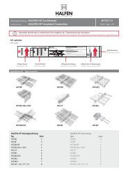
Machen Sie aus Ihren PDF Publikationen ein blätterbares Flipbook mit unserer einzigartigen Google optimierten e-Paper Software.
DKR DKR 11/12<br />
DEHA Conical Pipe Anchor<br />
6003+6004<br />
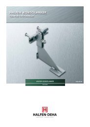
DEHA Konus-Rohranker<br />
6003+6004<br />
Assembly Instructions • Montageanleitung
DKR Assembly instructions DKR 11/12<br />
Identification<br />
Deutsch English<br />
Adaptor head<br />
Anchor shaft<br />
6004 6003<br />
M<br />
Load range:<br />
10<br />
20<br />
32<br />
Matching:<br />
10<br />
20<br />
32<br />
M30<br />
M39<br />
M52<br />
In general, observe the applicable accident prevention regulations.<br />
Observe the safety regulations set by the German Engineer Association<br />
(Verein Deutscher Ingenieure) in directive VDI/BV-BS 6205<br />
The DKR anchor is a two-part system;<br />
the anchor shaft (6003) and the reusable<br />
adaptor head (6004). Anchor<br />
shafts are available in different<br />
lengths, specified according to static<br />
demands for various load ranges.<br />
Only one adaptor head is designated<br />
for each load range. Anchor shaft and<br />
adaptor head are designed to ensure<br />
that only corresponding load ranges<br />
fit together. The load range is stamped<br />
on the adaptor head.<br />
Installation<br />
<br />
SW1<br />
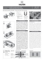
Installation:<br />
Before installation, the two components of the DKR lifting<br />
anchor are screwed together by hand until the thread is no<br />
longer visible.<br />
Lightly grease the thread of the anchor shaft to facilitate<br />
installation/removal. Also apply formwork oil to the adaptor<br />
head to prevent adhesion to the concrete.<br />
<br />
6173<br />
6153 + 6160<br />
Fixing to the formwork:<br />
Pre-assemble the recess former (6173-...) using the threaded<br />
plate and rod (6141-...) or threaded plate (6153-...).<br />
The anchor must be properly fixed to the reinforcement<br />
to secure the anchor and prevent it moving when pouring<br />
the concrete.<br />
6141<br />
Allen key sizes<br />
Adaptor<br />
SW1<br />
Sealing socket<br />
SW2<br />
Load range 10 10 17<br />
20 17 17<br />
32 19 19<br />
2 © 2012 HALFEN · Inst-DKR 11/2012 · www.halfen.com
DKR Assembly instructions DKR 11/12<br />
<br />
6175<br />
6171<br />
SW2<br />
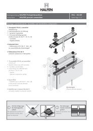
Striking the formwork:<br />
After the concrete has cured, remove the recess former;<br />
loosen the adaptor head slightly using an Allen key or unscrew<br />
and remove the head completely. Alternatively the<br />
special 2-point tool (6175) can be used instead of an Allen<br />
key.<br />
If the adaptor head is completely removed, replace with a<br />
sealing cap (6171). This is to ensure the thread of the<br />
anchor shaft is protected before final installation.<br />
An Allen key can also be used to remove the adaptor head.<br />
Deutsch English<br />
Note: loosen the adaptor head as soon as possible<br />
as it may prove difficult to remove from the<br />
hardened concrete if removal is delayed too long.<br />
Transporting<br />
<br />
Transporting:<br />
Remove the sealing socket and screw in the appropriate<br />
adaptor head completely before lifting. The anchor head is<br />
in the correct position if the conical part of the adapter<br />
head is completely recessed in the concrete. To make sure<br />
the adaptor head is fitted correctly check the dimension k<br />
between the top of the adaptor head and the top edge of<br />
the concrete (see table below).<br />
Load range<br />
k<br />
6102<br />
Check dimension<br />
Load range<br />
k [mm]<br />
10 15<br />
20 15<br />
32 23<br />
© 2012 HALFEN · Inst-DKR 11/2012 · www.halfen.com<br />
3
DKR Assembly instructions DKR 11/12<br />
Deutsch English<br />
After screwing in the adaptor head; lifting is with<br />
a universal head lifting clutch (6102) suitable for the<br />
attached load range. Use a spreader beam if necessary.<br />
Alternatively, lifting is possible with the turning and lifting<br />
link (6116). If the DKR Anchors are positioned in the apex<br />
(in pipes) keep the spread angle below 60° when lifting.<br />
Spread angle ≤ 60°<br />
Closing and sealing the recess<br />
<br />
After the precast element has been finally installed, the<br />
adaptor head can be unscrewed and removed. Use an Allen<br />
key SW1 (see page 2); or alternatively use a special 2-point<br />
tool (6175).<br />
Note: the adaptor head is re-useable.<br />
Then screw in the sealing cap until the rubber sealing ring<br />
is no longer visible. Use an Allen key SW2 (see page 2).<br />
Seal the recess using the fibre-concrete DEHA VKF Recess<br />
filler (6172) or fill with mortar.<br />
We recommend using an appropriate cement with a watertightness<br />
of 5 bar to fix the fibre-concrete DEHA Recess filler.<br />
Recommended adhesives; Carbolan or Carbopast,<br />
supplier; Minova, Essen.<br />
4 © 2012 HALFEN · Inst-DKR 11/2012 · www.halfen.com
DKR Montageanleitung DKR 11/12<br />
Kennzeichnung<br />
Adapterkopf<br />
Ankerschaft<br />
6004 6003<br />
M<br />
Lastklasse:<br />
10<br />
20<br />
32<br />
Zuordnung:<br />
10<br />
20<br />
32<br />
M30<br />
M39<br />
M52<br />
Generell sind die Unfallverhütungsvorschriften zu beachten. Die Sicherheitsregeln<br />
für Transportanker gemäß der VDI-Richtlinie VDI/BV-BS 6205<br />
sind einzuhalten.<br />
Der DKR-Anker besteht aus zwei Teilen,<br />
dem Ankerschaft 6003 und dem<br />
wiederverwendbaren Adapterkopf<br />
6004. Für jede Lastklasse gibt es unterschiedlich<br />
lange Ankerschäfte, die<br />
nach statischen Erfordernissen festgelegt<br />
werden. Für jede Lastklasse gibt<br />
es nur einen Adapterkopf. Ankerschaft<br />
und Adapterkopf sind so konstruiert,<br />
dass nur die jeweiligen Lastklassen<br />
zusammenpassen. Die Lastklasse<br />
ist auf dem Adapterkopf<br />
aufgeprägt.<br />
Deutsch English<br />
Einbau<br />
<br />
SW1<br />
Montage:<br />
Für den Einsatz als Transportanker müssen beide Teile von<br />
Hand zusammengeschraubt werden, bis das Gewinde nicht<br />
mehr sichtbar ist.<br />
Zum leichteren Eindrehen und Lösen sollte vorher das<br />
Gewinde des Ankerschaftes etwas eingefettet werden und<br />
der Adapterkopf von außen mit Schalöl versehen werden,<br />
um ein Kleben am Beton zu verhindern.<br />
<br />
6173<br />
6153 + 6160<br />
Befestigung an der Schalung:<br />
Aussparungskörper (6173-...) mit Stanzblech mit Gewindestab<br />
(6141-...) oder Stanzblech mit Innengewinde<br />
(6153-...) vor<strong>mon</strong>tieren. Der Anker ist durch geeignete<br />
Maßnahmen an der Bewehrung zu befestigen, damit während<br />
des Betoniervorgangs die Lage gesichert ist.<br />
6141<br />
Schlüsselweiten<br />
Adapter<br />
SW1<br />
Dichtkappe<br />
SW2<br />
Lastklasse 10 10 17<br />
20 17 17<br />
32 19 19<br />
© 2012 HALFEN · Inst-DKR 11/2012 · www.halfen.com<br />
5
DKR Montageanleitung DKR 11/12<br />
Deutsch English<br />
<br />
6175<br />
6171<br />
SW2<br />
Ausschalen:<br />
Nach dem Betoniervorgang den Aussparungskörper entfernen<br />
und den Adapterkopf mittels Sechskantschlüssel um einige<br />
Umdrehungen vom Beton lösen oder vollständig herausdrehen.<br />
Alternativ kann auch ein spezieller Zweipunkt-<br />
Schlüssel 6175 verwendet werden.<br />
Nach vollständigem Entfernen des Adapterkopfes sollte die<br />
Dichtkappe 6171 aufgeschraubt werden. Dadurch wird das<br />
Gewinde des Ankerschafts während der Lagerung geschützt.<br />
Dies kann ebenfalls mit einem Inbusschlüssel erfolgen.<br />
Wird der Adapterkopf erst nach dem Verlegen<br />
vom Beton gelöst, besteht die Möglichkeit, dass<br />
sich der Adapterkopf vom ausgehärteten Beton<br />
nur schwer wieder entfernen lässt.<br />
Transportieren<br />
<br />
Transport:<br />
Für den Transport die Dichtkappe entfernen und den passenden<br />
Adapterkopf vollständig eindrehen. Der Adapterkopf<br />
hat die richtige Position, wenn der konische Teil sich<br />
vollständig im Beton befindet und eine halbkugelförmige<br />
Aussparung vorhanden ist. Zur Überprüfung des korrekten<br />
Sitzes des Adapterkopfes kann das Maß k zwischen Oberkante<br />
Adapterkopf und Oberkante Beton überprüft werden<br />
(siehe Tabelle).<br />
Lastklasse<br />
k<br />
6102<br />
Prüfmaß<br />
Lastklasse<br />
k [mm]<br />
10 15<br />
20 15<br />
32 23<br />
6 © 2012 HALFEN · Inst-DKR 11/2012 · www.halfen.com
DKR Montageanleitung DKR 11/12<br />
Nach Einschrauben des Adapterkopfes erfolgt der Transport<br />
mit der zur Lastklasse passenden Universalkopf-Kupplung<br />
6102, ggfs. mit Traverse. Alternativ kann der Transport mit<br />
der Dreh- und Transportkupplung 6116 erfolgen.<br />
Bei der Anordnung der DKR-Anker in Scheitellage ist ein<br />
Spreizwinkel von ≤ 60° einzuhalten.<br />
Deutsch English<br />
Spreizwinkel ≤ 60°<br />
Aussparung abdichten und verschließen<br />
<br />
Befindet sich das Betonteil an seinem Einbauort, wird der<br />
Adapterkopf herausgedreht, dazu den Sechskant SW1 (siehe<br />
Seite 5) einsetzen; alternativ kann auch ein spezieller Zweipunkt-Schlüssel<br />
6175 verwendet werden.<br />
Hinweis: Der Adapterkopf kann wiederverwendet werden.<br />
Anschließend wird die Dichtkappe soweit aufgeschraubt,<br />
dass die Gummidichtung nicht mehr sichtbar ist. Dazu den<br />
Sechskant SW2 (siehe Seite 5) verwenden.<br />
Danach die halbkugelförmige Aussparung mit dem DEHA<br />
VKF Verschlusskörper 6172 aus Faserbeton verschließen<br />
oder mit Mörtel auffüllen.<br />
Zum Einkleben des DEHA Verschlusskörpers aus Faserbeton<br />
empfehlen wir die Verwendung eines geeigneten Klebers,<br />
mit dem eine Wasserdichtigkeit bis 5 bar erzielt wird.<br />
Empfehlung: 'Carbolan' oder 'Carbopast' der Firma Minova.<br />
© 2012 HALFEN · Inst-DKR 11/2012 · www.halfen.com<br />
7
CONTACT HALFEN WORLDWIDE<br />
HALFEN is represented by subsidiaries in the following 14 countries, please contact us:<br />
Austria<br />
Belgium /<br />
Luxembourg<br />
China<br />
Czech Republic<br />
France<br />
Germany<br />
Italy<br />
Netherlands<br />
Norway<br />
Poland<br />
Sweden<br />
Switzerland<br />
United Kingdom /<br />
Ireland<br />
United States of<br />
America<br />
HALFEN Gesellschaft m.b.H.<br />
Leonard-Bernstein-Str. 10<br />
1220 Wien<br />
HALFEN N.V.<br />
Borkelstraat 131<br />
2900 Schoten<br />
HALFEN Construction Accessories Distribution Co.Ltd.<br />
Room 601 Tower D, Vantone Centre<br />
No.A6 Chao Yang Men Wai Street<br />
Chaoyang District<br />
Beijing · P.R. China 100020<br />
HALFEN-DEHA s.r.o.<br />
Business Center Šafránkova<br />
Šafránkova 1238/1<br />
155 00 Praha 5<br />
HALFEN S.A.S.<br />
18, rue Goubet<br />
75019 Paris<br />
HALFEN Vertriebsgesellschaft mbH<br />
Katzbergstrasse 3<br />
40764 Langenfeld<br />
HALFEN S.r.l. Soc. Unipersonale<br />
Via F.lli Bronzetti N° 28<br />
24124 Bergamo<br />
HALFEN b.v.<br />
Oostermaat 3<br />
7623 CS Borne<br />
HALFEN AS<br />
Postboks 2080<br />
4095 Stavanger<br />
HALFEN Sp. z o.o.<br />
Ul. Obornicka 287<br />
60-691 Poznan<br />
<strong>Halfen</strong> AB<br />
Box 150<br />
435 23 Mölnlycke<br />
HALFEN Swiss AG<br />
Hertistrasse 25<br />
8304 Wallisellen<br />
HALFEN Ltd.<br />
Humphrys Road · Woodside Estate<br />
Dunstable LU5 4TP<br />
HALFEN USA Inc.<br />
8521 FM 1976<br />
P.O. Box 547<br />
Converse, TX 78109<br />
Furthermore HALFEN is represented with sales offices and distributors worldwide.<br />
Please contact us: www.halfen.com<br />
Phone: +43 - 1 - 259 6770<br />
E-Mail: office@halfen.at<br />
Internet: www.halfen.at<br />
Phone: +32 - 3 - 658 07 20<br />
E-Mail: info@halfen.be<br />
Internet: www.halfen.be<br />
Phone: +86 - 10 5907 3200<br />
E-Mail: info@halfen.com<br />
Internet: www.halfen.cn<br />
Phone: +420 - 311 - 690 060<br />
E-Mail: info@halfen-deha.cz<br />
Internet: www.halfen-deha.cz<br />
Phone: +33 - 1 - 445231 00<br />
E-Mail: halfen@halfen.fr<br />
Internet: www.halfen.fr<br />
Phone: +49 - 2173 - 970 0<br />
E-Mail: info@halfen.de<br />
Internet: www.halfen.de<br />
Phone: +39 - 035 - 0760711<br />
E-Mail: info@halfen.it<br />
Internet: www.halfen.it<br />
Phone: +31 - 742 - 6714 49<br />
E-Mail: info@halfen.nl<br />
Internet: www.halfen.nl<br />
Phone: +47 - 51 82 34 00<br />
E-Mail: post@halfen.no<br />
Internet: www.halfen.no<br />
Phone: +48 - 61 - 622 14 14<br />
E-Mail: info@halfen.pl<br />
Internet: www.halfen.pl<br />
Phone: +46 - 31 - 98 58 00<br />
E-Mail: info@halfen.se<br />
Internet: www.halfen.se<br />
Phone: +41 - 44 - 849 78 78<br />
E-Mail: mail@halfen.ch<br />
Internet: www.halfen.ch<br />
Phone: +44 - 1582 - 47 03 00<br />
E-Mail: info@halfen.co.uk<br />
Internet: www.halfen.co.uk<br />
NOTES REGARDING THIS DOCUMENT<br />
Technical and design changes reserved. The information in this publication is based on state-of-the-art technology<br />
at the time of publication. We reserve the right to make technical and design changes at any time. <strong>Halfen</strong> GmbH<br />
shall not accept liability for the accuracy of the information in this publication or for any printing errors.<br />
The Quality Management System of <strong>Halfen</strong> GmbH is certified for the locations in Germany, France, the Netherlands,<br />
Austria, Poland, Switzerland and the Czech Republic acc. to DIN EN ISO 9001:2008, Certificate No. QS-281 HH.<br />
Fax: +43 - 1 - 259 - 6770 99<br />
Fax: +32 - 3 - 658 15 33<br />
Fax: +86 - 10 5907 3218<br />
Fax: +420 - 235 - 314308<br />
Fax: +33 - 1 - 445231 52<br />
Fax: +49 - 2173 - 970 225<br />
Fax: +39 - 035 - 0760799<br />
Fax: +31 - 742 6726 59<br />
Fax: +47 - 51 82 34 01<br />
Fax: +48 - 61 - 622 14 15<br />
Fax: +46 - 31 - 98 58 01<br />
Fax: +41 - 44 - 849 78 79<br />
Fax: +44 - 1582 - 47 03 04<br />
Phone: +1 800.323.68 96 Fax: +1 888 . 227.16 95<br />
E-Mail: info@halfen.com<br />
Internet: www.halfenusa.com<br />
© 2012 HALFEN GmbH, Germany<br />
applies also to copying in extracts.<br />
U - 424 - 11/12 PDF 11/12<br />
622