SER 150 ET - Grundig-info.de
SER 150 ET - Grundig-info.de
SER 150 ET - Grundig-info.de

Sie wollen auch ein ePaper? Erhöhen Sie die Reichweite Ihrer Titel.
YUMPU macht aus Druck-PDFs automatisch weboptimierte ePaper, die Google liebt.
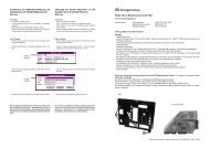
D Montageanleitung<br />
Satelliten-Einbau-Receiver <strong>SER</strong> <strong>150</strong> <strong>ET</strong><br />
<strong>SER</strong> <strong>150</strong> <strong>ET</strong>, Best. Nr. G.AD 2500 für TV-Chassis:<br />
CUC 1825, 1805 (Digi Basic), CUC 1826, 1827 (Digi Basic +), CUC 1806, 1828, 1829, 1830, 1836, 1929 (Digi Basic ++),<br />
CUC 1952, 1983, 1984, 1894, 1842 (Digi 6).<br />
Aufruf <strong>de</strong>s EPROM-Stan<strong>de</strong>s: Mit <strong>de</strong>n Fernbedienungstasten "" –> "OK" - Dialog Center wird eingeblen<strong>de</strong>t –> "AUX".<br />
Bei Geräten mit einem EPROM-Stand kleiner 19798 300 2000 (Digi Basic, Digi Basic +), sowie kleiner 19798 311 2000<br />
(DIGI 6), muß ein Tausch <strong>de</strong>s EPROMs vorgenommen wer<strong>de</strong>n.<br />
Bei Digi Basic ++ ist kein Tausch nötig.<br />
Das erfor<strong>de</strong>rliche EPROM erhalten Sie vom Zentralkun<strong>de</strong>ndienst unter <strong>de</strong>r Materialnummer 19798 300 2400 (Digi Basic,<br />
Digi Basic +), 19798 311 4700 (Digi 6).<br />
Bestellen können Sie unter <strong>de</strong>r Hotline-Nummer 0180/52318-40.<br />
Der Receiver <strong>SER</strong> <strong>150</strong> <strong>ET</strong> beinhaltet: SAT-Baustein 29504 106 2400, Fixierung 29700 216 0100<br />
Bedienungsanleitung 28017 941 7900, Montageanleitung 72010 020 0001<br />
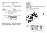
Montage Digi Basic:<br />
- Netzstecker ziehen und Gerät öffnen.<br />
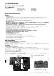
- Seitliche Rasthaken (Abb. 2, Pos. A) am Chassisrahmen links öffnen.<br />
- 2 Rastnasen (Abb. 2 Pos. B) oberhalb <strong>de</strong>r EURO-AV-Buchsen anheben und die Buchsenab<strong>de</strong>ckung seitlich wegklappen.<br />
- Den vorgestanzten Blindstopfen (Abb. 2, Pos. C) für <strong>de</strong>n SAT-Antennenanschluß in <strong>de</strong>r Buchsenab<strong>de</strong>ckung ausbrechen.<br />
- Bausteinhalter (Abb. 2, Pos. D) aushängen und 3 Haltezapfen (Abb. 2, Pos. E) abzwicken.<br />
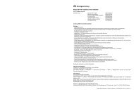
- CR32325 (3,3kΩ) auf <strong>de</strong>r Chassisplatte (neben <strong>de</strong>m Signalbaustein Pin 7), falls noch bestückt, entfernen.<br />
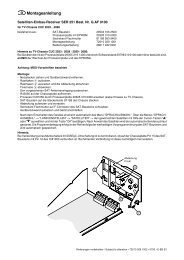
- Ersetzen Sie auf <strong>de</strong>m Signal-Baustein 29504 102 3400 und 29504 162 3400 <strong>de</strong>n Wi<strong>de</strong>rstand CR32128, wenn 4,7kΩ, durch<br />
einen Wi<strong>de</strong>rstand von 2,7kΩ, o<strong>de</strong>r schalten Sie einen Wi<strong>de</strong>rstand von 5,6kΩ parallel, (Abb. 1).<br />
- SAT-Baustein auf das Signal-Modul stecken und Bausteinhalter (Abb. 2 Pos. D) einrasten.<br />
- Buchsenab<strong>de</strong>ckung aufsetzen und einrasten.<br />
Achten Sie darauf, daß die Chassisplatte in <strong>de</strong>r Nut am unteren Rand <strong>de</strong>r Ab<strong>de</strong>ckung liegt (Abb. 2, Pos. F).<br />
- Arretieren Sie <strong>de</strong>n SAT-Baustein mit <strong>de</strong>r Fixierung (Abb. 2, Pos. G).<br />
- Geräterückwand aufsetzen und Gerät anschließen.<br />
- Nach <strong>de</strong>m Einschalten über das ATS-Menü –> "Dialogsprache" –> "Gerätestandort" –> "Kabel/Antenne" –> gewünschten<br />
Satelliten mit "OK" auswählen. Nach Anwahl <strong>de</strong>s Satelliten wird selbsttätig die richtige Oszillatorfrequenz eingestellt und<br />
<strong>de</strong>r automatische Sen<strong>de</strong>rsuchlauf gestartet. Die Programmbelegung erfolgt in <strong>de</strong>r Reihenfolge <strong>de</strong>r SAT-Baustein-<br />
Vorprogrammierung und wird automatisch gespeichert.<br />
Montage Digi 6:<br />
- Netzstecker ziehen und Gerät öffnen.<br />
- 2 Schrauben am unteren Rand <strong>de</strong>r Buchsenab<strong>de</strong>ckung herausschrauben (Abb. 2, Pos. H).<br />
- 2 Rastnasen (Abb. 2, Pos. B) oberhalb <strong>de</strong>r EURO-AV-Buchsen anheben und die Ab<strong>de</strong>ckung nach hinten wegziehen.<br />
- Den vorgestanzten Blindstopfen (Abb. 2, Pos. C) für <strong>de</strong>n SAT-Antennenanschluß in <strong>de</strong>r Buchsenab<strong>de</strong>ckung ausbrechen.<br />
- Bausteinhalter (Abb. 2, Pos. D) aushängen und SAT-Baustein auf das Signal-Modul stecken.<br />
- Buchsenab<strong>de</strong>ckung aufsetzen und festschrauben.<br />
- Arretieren Sie <strong>de</strong>n SAT-Baustein mit <strong>de</strong>r Fixierung (Abb. 2, Pos. G).<br />
- Geräterückwand aufsetzen und Gerät anschließen.<br />
- Nach <strong>de</strong>m Einschalten über das ATS-Menü –> "Dialogsprache" –> "Gerätestandort" –> "Kabel/Antenne" –> gewünschten<br />
Satellit mit "OK" auswählen. Nach Anwahl <strong>de</strong>s Satelliten wird selbsttätig die richtige Oszillatorfrequenz eingestellt und <strong>de</strong>r<br />
automatische Sen<strong>de</strong>rsuchlauf gestartet. Die Programmbelegung erfolgt in <strong>de</strong>r Reihenfolge <strong>de</strong>r SAT-Baustein-Vorprogrammierung<br />
und wird automatisch gespeichert.<br />
GB Fitting Instructions<br />
Built-in Satellite Receiver <strong>SER</strong> <strong>150</strong> <strong>ET</strong><br />
<strong>SER</strong> <strong>150</strong> <strong>ET</strong>, Or<strong>de</strong>r No. G.AD 2500 for TV chassis :<br />
CUC 1825, 1805 (Digi Basic), CUC 1826, 1827 (Digi Basic +), CUC 1806, 1828, 1829, 1830, 1836, 1929 (Digi Basic ++),<br />
CUC 1952, 1983, 1984, 1894, 1842 (Digi 6).<br />
Calling up the EPROM version number: Press the remote control buttons "" –> "OK" - Dialog Center is fa<strong>de</strong>d in –> "AUX".<br />
Should the EPROM software version be lower than 19789 300 2000 (Digi Basic, Digi Basic +) or lower than 19798 311 2000<br />
(Digi 6), the EPROM must be changed.<br />
The EPROM of Digi Basic ++ needs not to be replaced.<br />
The necessary EPROM is available from the Central Customer Service, part number 19798 300 2400 (Digi Basic,<br />
Digi Basic +), 19798 311 4700 (Digi 6).<br />
You can place your or<strong>de</strong>rs calling the hotline number 0180/52318-40.<br />
The <strong>SER</strong> <strong>150</strong> <strong>ET</strong> receiver consists of: SAT Module 29504 106 2400, Fixing Device 29700 216 0100<br />
User Manual 28017 941 7900, Fitting Instructions 72010 020 0001<br />
72010 020 0001 E-BS33 0599
Assembly Digi Basic:<br />
- Disconnect the mains plug and open the TV set.<br />
- Open the lateral catch (fig. 2, pos. A) on the left of the chassis frame.<br />
- Lift the 2 catches (fig. 2, pos. B) above the Scart sockets and hinge away the socket cover to the si<strong>de</strong>.<br />
- Break off the prepunched dummy plug (fig. 2, pos. C) for SAT aerial connection on the socket cover.<br />
- Detach the module hol<strong>de</strong>r (fig. 2, pos. D) and pinch off the 3 holding lugs (fig. 2, pos. E).<br />
- Remove CR32325 (3.3kΩ) on the chassis board (besi<strong>de</strong> the Signal Module pin 7) if not yet done.<br />
- If the rating is 4.7kΩ, change CR32128 on the Signal Modules 29504 102 3400 and 29504 162 3400 to a 2.7kΩ resistor<br />
or connect a resistor of 5.6kΩ in parallel (Fig.1).<br />
- Insert the SAT Module into the Signal Module and lock the module hol<strong>de</strong>r into place (Fig. 2, pos. D).<br />
- Attach the socket cover and lock it into place.<br />
Take care that the chassis board fits into the groove at the lower edge of the cover (Fig. 2, pos. F).<br />
- Fasten the SAT Module with the fixing <strong>de</strong>vice (Fig. 2, pos. G).<br />
- Refit the rear of the cabinet and connect the TV set.<br />
- Switch on the TV set. Via the ATS menu –> "Adjust language on screen" –> "Adjust country" –> "Cable/Aerial" –> select<br />
the <strong>de</strong>sired satellite with "OK". On selection of the <strong>de</strong>sired satellite, the correct oscillator frequency will be set automatically<br />
and the automatic tuning system will start. The programmes are allocated in the or<strong>de</strong>r preprogrammed in the SAT Module<br />
and are then stored automatically.<br />
Assembly Digi 6:<br />
- Disconnect the mains plug and open the TV set.<br />
- Undo 2 screws at the lower edge of the socket cover (Fig 2, pos. H).<br />
- Lift the 2 locking lugs (Fig. 2, pos. B) above the Scart sockets and pull off the cover towards the rear si<strong>de</strong>.<br />
- Break off the prepunched dummy plug (fig. 2, pos. C) for SAT aerial connection on the socket cover.<br />
- Detach the module hol<strong>de</strong>r (Fig. 2, pos. D) and insert the SAT Module into the Signal Module.<br />
- Attach the socket cover and fasten it with the screws.<br />
- Fasten the SAT Module with the fixing <strong>de</strong>vice (Fig. 2, pos. G).<br />
- Refit the rear of the cabinet and connect the TV set.<br />
- Switch on the TV set. Via the ATS menu –> "Adjust language on screen" –> "Adjust country" –> "Cable/Aerial" –> select<br />
the <strong>de</strong>sired satellite with "OK". On selection of the <strong>de</strong>sired satellite, the correct oscillator frequency will be set automatically<br />
and the automatic tuning system will start. The programmes are allocated in the or<strong>de</strong>r preprogrammed in the SAT Module<br />
and are then stored automatically.<br />
CR32134<br />
CR32135<br />
CT32134<br />
EB<br />
CR32063<br />
CBR12<br />
CR32026<br />
CD32032<br />
CD32031<br />
CR32088<br />
9<br />
8 CIC32030<br />
EB<br />
CT32064<br />
CR32089<br />
B E<br />
CR32119<br />
CBR11<br />
CBR9<br />
CR32028<br />
CR32109<br />
CC32106<br />
CR32114<br />
CBR024<br />
CR32115<br />
CR32144<br />
CR32103<br />
CT32124<br />
E<br />
B<br />
CC32121<br />
CC32124<br />
CR32133<br />
CC32123<br />
CR32123<br />
CC32122<br />
E<br />
CR32112<br />
CR32<strong>150</strong><br />
BCT32122<br />
Abbildung 1 / Figure 1<br />
CC32030<br />
CBR1<br />
1<br />
16<br />
CR32161<br />
CR32162<br />
CR32160<br />
CT32026<br />
E<br />
B<br />
CBR19<br />
CC32029<br />
CBR027<br />
CR32251<br />
CR32154<br />
E<br />
B<br />
CT32251<br />
CC32238<br />
CT32128<br />
CR32128<br />
E<br />
B<br />
CT32132<br />
EB<br />
CR32132<br />
CR32146<br />
CBR028<br />
CBR3<br />
CR32147<br />
EB<br />
CT32125<br />
CR32145<br />
29304-783.49 4LS(06)<br />
Signal-ZF-Baustein<br />
29504 102 3400/-162 3400<br />
D<br />
Digi Basic<br />
G<br />
Digi 6<br />
H<br />
CR 32128<br />
B<br />
C<br />
F<br />
B<br />
E<br />
A<br />
Abbildung 2 / Figure 2