Montageanl. PIP 2 D/GB - Grundig-info.de
Montageanl. PIP 2 D/GB - Grundig-info.de
Montageanl. PIP 2 D/GB - Grundig-info.de

Sie wollen auch ein ePaper? Erhöhen Sie die Reichweite Ihrer Titel.
YUMPU macht aus Druck-PDFs automatisch weboptimierte ePaper, die Google liebt.
D <strong>Montageanl</strong>eitung<br />
Modul <strong>PIP</strong> 2 (mit <strong>PIP</strong>-Tuner)<br />
Modul <strong>PIP</strong> 2, Best. Nr. G.AD 2300 bestehend aus:<br />
- <strong>PIP</strong>-Baustein 29504-165.97<br />
- Antennenweiche 29620-013.01 o<strong>de</strong>r 29620-013.03<br />
- Montagematerial mit Buchsenab<strong>de</strong>ckung<br />
Montage :<br />
- Netzstecker ziehen und Gerät öffnen.<br />
- Beigepackte Antennenweiche auf <strong>de</strong>n <strong>PIP</strong>-Tuner aufsetzen und die 2-pol. grüne Leitung mit <strong>de</strong>m roten Steckerunterteil<br />
"ST 12" <strong>de</strong>s <strong>PIP</strong>-Bausteins verbin<strong>de</strong>n.<br />
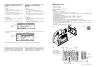
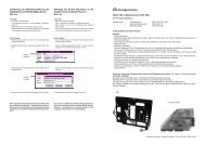
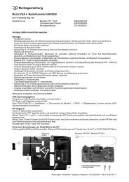
- Bausteinhalter aushängen und <strong>PIP</strong>-Baustein auf die vorgesehene Steckerleiste "<strong>PIP</strong>" <strong>de</strong>s Signalchassis stecken (Abb).<br />
- Bausteinhalter wie<strong>de</strong>r einrasten, dabei muß <strong>de</strong>r Halter (Abb. Pos. A) das <strong>PIP</strong>-Modul führen.<br />
- Schwarzes Kabel mit Antennenstecker durch das vorgestanzte Langloch in <strong>de</strong>r Ab<strong>de</strong>ckung (Abb. Pos. B) schieben und<br />
auf <strong>de</strong>n Gerätetuner aufstecken.<br />
- Schwarzes Kabel mit Antennenbuchse durch das Langloch in <strong>de</strong>r Ab<strong>de</strong>ckung (Abb. Pos. B) schieben und mit <strong>de</strong>r<br />
Kontermutter auf <strong>de</strong>r Ab<strong>de</strong>ckplatte befestigen (das bereits durchgesteckte Steckerkabel seitlich im Langloch verlegen).<br />
- Bei <strong>de</strong>r Antennenweiche 29620-013.03 wird das schwarze Kabel mit <strong>de</strong>r Antennenbuchse im Langloch <strong>de</strong>r Ab<strong>de</strong>ckung<br />
eingerastet (Abb. Pos. B).<br />
- Geräterückwand aufsetzen und Gerät anschließen.<br />
- Die <strong>PIP</strong>-Taste ruft das <strong>PIP</strong>-Bild auf. Über die Menüführung können Sie die <strong>PIP</strong>-Position und <strong>PIP</strong>-Größe verän<strong>de</strong>rn.<br />
- Für <strong>de</strong>n <strong>PIP</strong>-Abgleich die Fernbedientaste "<strong>PIP</strong>" gedrückt halten und das Gerät mit <strong>de</strong>m Netzschalter einschalten. Mit <strong>de</strong>n<br />
Tasten die vertikale und horizontale <strong>PIP</strong>-Position so einstellen, daß das Kleinbild nicht vom Bildschirmrand<br />
begrenzt wird. Einstellung mit <strong>de</strong>r Taste "OK" speichern.<br />
<strong>GB</strong> Fitting Instructions<br />
Module <strong>PIP</strong> 2 (with <strong>PIP</strong> Tuner)<br />
Module <strong>PIP</strong> 2, or<strong>de</strong>r no. G.AD 2300<br />
- <strong>PIP</strong> Module 29504-165.97<br />
- Antenna Splitter 29620-013.01 or 29620-013.03<br />
- Fitting material with socket cover<br />
Assembly :<br />
- Disconnect the mains plug and open the TV receiver.<br />
- Insert the Antenna Splitter inclu<strong>de</strong>d in the <strong>de</strong>livery into the <strong>PIP</strong> Tuner and connect the 2-core green lead with the red<br />
connector base "ST 12" on the <strong>PIP</strong> Module.<br />
- Detach the module hol<strong>de</strong>r and plug the <strong>PIP</strong> Module into the "<strong>PIP</strong>" multipoint connector provi<strong>de</strong>d for it on the Signal Chassis<br />
(Fig.).<br />
- Re-insert the module hol<strong>de</strong>r using it as a gui<strong>de</strong> (Fig. Pos. A) for the <strong>PIP</strong> Module.<br />
- Lead the black cable with the antenna plug through the pre-punched elongated hole in the cover (Fig. Pos. B) and plug it<br />
into the TV Tuner.<br />
- Pass the black cable with the antenna socket through the pre-punched elongated hole in the cover (Fig. Pos. B) and fasten<br />
it with the counternut to the cover (with the black cable with the plug being located in the elongated part of the hole).<br />
- With the Antenna Splitter 29620-013.03 the black cable with the antenna socket locks into the elongated hole of the cover<br />
(Fig. Pos. B).<br />
- Refit the rear of the cabinet and connect the TV receiver.<br />
- The small picture (<strong>PIP</strong>) can be called up by pressing the <strong>PIP</strong> button. Gui<strong>de</strong>d by the menu, you can change the <strong>PIP</strong> position<br />
and size.<br />
- For shifting the <strong>PIP</strong>, press and hold the "<strong>PIP</strong>" button on the remote control handset and switch the TV receiver on with the<br />
mains switch. With the buttons adjust the <strong>PIP</strong> position in the vertical and horizontal direction so that the small<br />
picture does not bor<strong>de</strong>r on the edge of the screen. Store with "OK".<br />
72010-020.16 ZKD 0497 VK 22
Abbildung<br />
Figure<br />
A<br />
B<br />
<strong>PIP</strong> Baustein