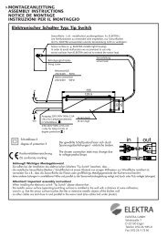
Panikverschluss PED 200 / 210 Panic exit device PED 200 / 210
Panikverschluss PED 200 / 210 Panic exit device PED 200 / 210
Panikverschluss PED 200 / 210 Panic exit device PED 200 / 210

Erfolgreiche ePaper selbst erstellen
Machen Sie aus Ihren PDF Publikationen ein blätterbares Flipbook mit unserer einzigartigen Google optimierten e-Paper Software.
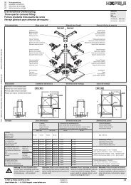
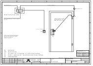
Einbauphasen<br />
9 Installation phases<br />
Nacheinander das Zentralschloss (1), die obere Falle (2) und die untere Falle (3) befestigen.<br />
Install the central lock (1), the upper latch (2) and the lower latch (3) consecutively.<br />
9a<br />
16 (41 max)<br />
3<br />
1<br />
2<br />
11<br />
V1<br />
V1<br />
V1<br />
V1<br />
V1<br />
V1<br />
Bei geschlossener Tür den unteren Spitzriegel in die Führung setzen (4) und in das Bodenschließblech fallen lassen.<br />
Place the lower shoot bolt in the guide (4) when the door is closed and let it drop into the floor socket.<br />
9b<br />
4<br />
Den oberen Spitzriegel in die Führung (5a) einfügen. Die Stange wie auf Abbildung (5b) ausrichten und ganz in den Spitzriegel<br />
einsetzen. Die Stange am Zentralschloss verbinden (5c). Die untere Stange ganz in den Spitzriegel einsetzen (6a) und sie am<br />
Zentralschloss verbinden (6b).<br />
9c<br />
Insert the upper shoot bolt in the guide (5a). Align the bar as in the figure (5b) and completely insert into the shoot bolt.<br />
Connect the bar to the central lock (5c). Insert the lower bar completely in the shoot bolt (6a) and connect it on the central<br />
lock (6b).<br />
5c-6b<br />
CLIK<br />
5a<br />
5b<br />
5c<br />
CLIK<br />
CLIK<br />
6b<br />
6a<br />
HDE 19.06.2013 Maße in mm – Dimensions in mm<br />
12/16