Panikverschluss PED 200 / 210 Panic exit device PED 200 / 210
Panikverschluss PED 200 / 210 Panic exit device PED 200 / 210
Panikverschluss PED 200 / 210 Panic exit device PED 200 / 210

Sie wollen auch ein ePaper? Erhöhen Sie die Reichweite Ihrer Titel.
YUMPU macht aus Druck-PDFs automatisch weboptimierte ePaper, die Google liebt.
<strong>Panikverschluss</strong> <strong>PED</strong> <strong>200</strong> / <strong>210</strong><br />
<strong>Panic</strong> <strong>exit</strong> <strong>device</strong> <strong>PED</strong> <strong>200</strong> / <strong>210</strong><br />
901.02.449<br />
903.03.014<br />
901.02.459<br />
903.03.016<br />
901.02.365<br />
901.02.375<br />
902.02.383<br />
901.02.355<br />
Montage- und Wartungsanleitung an den Benutzer aushändigen!<br />
Hand out installation and maintenance instructions to the user!<br />
WICHTIG<br />
Dieses Produkt erfüllt die Merkmale der<br />
EN 1125:<strong>200</strong>8. Änderungen am Produkt<br />
sind nicht zulässig.<br />
IMPORTANT<br />
This product meets the requirements of EN<br />
1125:<strong>200</strong>8. Modifications on the product are not<br />
permitted.<br />
Zertifizierte Konfigurationen<br />
Certified configurations<br />
HDE 19.06.2013 Maße in mm – Dimensions in mm<br />
KW12792.TE<br />
1/16
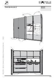
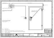
Anwendungsbereich<br />
1 Area of application<br />
D<br />
E<br />
Der Anwendungsbereich des Paniktürverschlusses ist wie folgt begrenzt:<br />
The area of application of the panic lock is as follows::<br />
Maximales Türgewicht<br />
Max. door weight<br />
Maximale Höhe der Tür<br />
Max. door height<br />
Maximale Breite der Tür<br />
Max. door width<br />
Temperaturbereich<br />
Temperature range<br />
<strong>200</strong> Kg 2520 mm 1320 mm -10°C +60°C<br />
X<br />
Y<br />
Fig. 1<br />
D<br />
E<br />
Die Länge der Betätigungsstange X muß der Breite der Tür Y angepasst werden.<br />
Die Länge X darf nie weniger als 60% der Türbreite Y betragen (siehe Fig.1).<br />
Türflügel und Rahmen müssen aus einem ausreichend steifen Material gefertigt sein, um eine eventuelle Verbiegung<br />
während der Betätigung auf max. 5 mm in jeder Position zu begrenzen.<br />
Die Befestigung des <strong>Panikverschluss</strong>es an der Tür muss auf Material erfolgen, das eine Zugfestigkeit von > 1,5 KN pro<br />
Schraube gewährleistet.<br />
The length of touchbar X must be adjusted to door width Y.<br />
Length X may never be less than 60% of door width Y (see fig. 1).<br />
The door and frame must be manufactured of a sufficiently rigid material, in order to limit any potential bending to max.<br />
5 mm in any position during the operation.<br />
The panic <strong>exit</strong> <strong>device</strong> on the door must be mounted on material that guarantees a tensile strength of > 1.5 KN per<br />
screw.<br />
Niemals Außenbeschläge an die Innenseite der Tür montieren.<br />
Außenbeschlag ausschließlich an der Außenseite der Tür verwenden.<br />
Hinweise zur Montage siehe „Montageanleitung Drücker für <strong>PED</strong> <strong>200</strong> / <strong>PED</strong> <strong>210</strong>“.<br />
Never assemble external fittings on the inside of the door.<br />
Use the external fitting only on the outside of the door.<br />
For mounting the fittings refer to "Installation instructions for the lever handle for <strong>PED</strong> <strong>200</strong> / <strong>PED</strong> <strong>210</strong>".<br />
HDE 19.06.2013 Maße in mm – Dimensions in mm<br />
2/16
Eignung der Produkte für den Einsatz an Feuer-/Rauchschutztüren<br />
2 Suitability of the products for use on fire resistant/smoke control doors<br />
Die Produkte sind für den Einsatz an Feuer-/Rauchschutztüren geeignet.<br />
The products are suitable for use on fire resistant/smoke control doors.<br />
Häfele GmbH & Co KG<br />
Adolf-Häfele-Str. 1<br />
D-72202 Nagold<br />
1121 - CPD - AAA 025<br />
EN 1125:<strong>200</strong>8 3 7 6 B 1 4 2 2 A<br />
A<br />
H<br />
L<br />
HDE 19.06.2013 Maße in mm – Dimensions in mm<br />
H<br />
Hmax=3400mm<br />
Lmax=1500mm<br />
L<br />
Die Eignung dieser Produkte mit Feuer-/Rauchschutztüren wurde auf der Basis einer Prüfung nach der Norm<br />
EN 1634-1 zertifiziert.<br />
The suitability of these products for use on fire resistant/smoke control doors was certified based on a test<br />
according to standard EN 1634-1.<br />
Diese Produkte erfüllen die Norm EN 1125:<strong>200</strong>8 und wurden zertifiziert durch Warrington Certification Limited<br />
(EC Notified Body number 1121) gemäß der Bauproduktrichtlinie 89/106/EWG.<br />
These products fulfill standard EN 1125:<strong>200</strong>8 and were certified under the building product guideline 89/106/EWG by<br />
Warrington Certification Limited (EC Notified Body number 1121).<br />
3/16
Montageanleitung<br />
3 Installation instructions<br />
D HINWEIS:<br />
Die gemäß der europäischen Norm hergestellten Paniktürverschlüsse gewährleisten eine hohe Sicherheit für Personen<br />
und eine angemessene Sicherheit für Sachwerte, vorausgesetzt sie werden auf in gutem Zustand befindlichen Türen<br />
und Rahmen montiert.<br />
1.<br />
2.<br />
3.<br />
4.<br />
5.<br />
6.<br />
Vor der Montage des Verschlusses an der Tür, muß die Tür auf einwandfreie Funktion und Leichtgängigkeit geprüft<br />
werden. Den Verschluss nicht an Türen mit Wabenfüllung montieren, es sei denn, der Beschlag ist vom Hersteller<br />
speziell für diese Türen entwickelt worden.<br />
Sicherstellen, ob die Tür für die Montage des Verschlusses geeignet ist. Der Achsabstand der Scharniere und die<br />
Überschneidung der Türflügel müssen ein gleichzeitiges Öffnen der Türflügel ermöglichen (siehe Punkt 3). Das Spiel<br />
zwischen den Türflügeln darf nicht von den Angaben des Türherstellers abweichen. Die beweglichen Teile dürfen sich<br />
nicht gegenseitig beeinträchtigen etc.<br />
Vor Montage eines Paniktürverschlusses an Feuer-/Rauchschutztüren muss die Bescheinigung der Feuerbeständigkeit<br />
der Tür untersucht werden, auf der der Paniktürverschluss für die Prüfung montiert wurde, um die Eignung an einer<br />
Feuerschutztür festzustellen.<br />
Es muss darauf geachtet werden, dass die an der Tür montierten Dichtungen die korrekte Funktion des Paniktürverschlusses<br />
nicht beeinträchtigen.<br />
Bei zweiflügeligen Türen mit überfälztem Mittelanschlag und Montage von Panikverschlüssen an beiden Flügeln muss<br />
geprüft werden, dass sich jeder Flügel öffnet, wenn der jeweilige Verschluß betätigt wird. Für diesen Zweck kann eine<br />
Betätigungsstange zum Mitnehmen des aktiven Flügels geliefert werden.<br />
Falls der Paniktürverschluss für die Montage an einer Glastür vorgesehen ist, muss das Glas gehärtet oder beschichtet sein<br />
(Verbundglas).<br />
Zur Montage von Paniktürverschlüssen an rahmenlosen Glas-, Metall oder Holztüren kann der Einsatz von anderen<br />
Befestigungssystemen erforderlich sein.<br />
7. Die Paniktürverschlüsse sind, wenn nicht ausdrücklich vom Hersteller angegeben, nicht für Pendeltüren vorgesehen.<br />
8.<br />
9.<br />
10.<br />
11.<br />
12.<br />
Während der Montage müssen die Anleitungen zur Befestigung genau befolgt werden. Diese Anleitungen sowie alle<br />
Wartungsanleitungen sind vom Monteur an den Benutzer auszuhändigen.<br />
Die horizontale Betätigungsstange des Paniktürverschlusses sollte normalerweise in einer Höhe zwischen 900 mm und<br />
1100 mm über der Oberfläche des fertigen Fußbodens bei geschlossener Türe montiert werden. Falls bekannt ist, dass<br />
die Mehrheit der Benutzer der Räumlichkeit kleine Kinder sind, muss eine Reduzierung der Anbringungshöhe in Betracht<br />
gezogen werden.<br />
Die horizontale Betätigungsstange muss so montiert werden, dass eine maximale Nutzbreite erreicht wird, mindestens<br />
aber 60% der Türbreite.<br />
Die Schließelemente und die Schließbleche müssen so befestigt werden, dass sie sicher ineinander schließen.<br />
Es muss darauf geachtet werden, dass die Schließelemente in geöffnetem Zustand weder überhängen noch den freien<br />
Lauf der Tür behindern.<br />
Falls der Paniktürverschluss an zweiflügeligen Türen mit überfälztem Mittelanschlag und Türschließern montiert werden<br />
soll, sollte ein Schließfolgeregler nach EN 1158 installiert werden, um die richtige Schließfolge der Tür sicherzustellen.<br />
Dies ist besonders wichtig bei Feuer-/Rauchschutztüren.<br />
13.<br />
14.<br />
15.<br />
16.<br />
Für das Zuhalten der Tür in der geschlossenen Stellung ist es ausreichend, die in der europäischen Norm<br />
EN 1125:<strong>200</strong>8 aufgeführten Vorrichtungen zu verwenden. Dies verbietet aber nicht die Installation von Türschließern.<br />
Falls ein Türschließer installiert wird, muss beachtet werden, dass hierdurch die Betätigung der Tür durch Kinder, ältere<br />
Personen oder Behinderte nicht erschwert wird.<br />
Alle beiliegenden Schließbleche oder Unterlegplatten müssen unter Berücksichtigung der europäischen Norm<br />
EN 1125:<strong>200</strong>8 montiert werden.<br />
An der Innenseite der Türe muss ein Schild mit der Aufschrift „Zum Öffnen hier drücken“ oder ein Piktogramm angebracht<br />
werden. Das Schild / Piktogramm muss unmittelbar oberhalb des Paniktürverschlusses oder auf der Betätigungsstange<br />
(wenn sie eine ausreichend große ebene Fläche für die Beschriftung hat) angebracht werden. Die Fläche für<br />
das Piktogramm muss mindestens 8000 mm² betragen und das Piktogramm weiß auf grünem Hintergrund sein. Es<br />
muss so ausgelegt sein, dass der Pfeil auf die Betätigungsstange zeigt, falls montiert.<br />
17. Die Kontaktflächen zwischen Falle und Schließblech mit einem Fett schmieren, das eine für den Anwendungsbereich<br />
angemessene Einsatztemperatur besitzt (z.B. FINA Marson EPL2 oder gleichwertig).<br />
HDE 19.06.2013 Maße in mm – Dimensions in mm<br />
4/16
E<br />
NOTE:<br />
The <strong>device</strong>s for panic <strong>exit</strong> <strong>device</strong>s manufactured according to the European Standard guarantee a high level of safety to<br />
persons and sufficient safety for property values, provided they are fitted on doors and frames in good condition<br />
1. Prior to installing a lock on a door, the door must be inspected for its perfect function and easy movement. Do not install<br />
the lock on honeycomb core doors unless the fitting has been specifically developed for these doors by the manufacturer.<br />
Verify that the door is suitable for the installation of this lock. The axis distance of the hinges and the overlap of the door<br />
leafs must allow to simultaneously open the door leafs (see item 3). The play between the door leafs may not deviate<br />
from the door manufacturer’s specifications. Movable parts may not interfere with each other, etc.<br />
2. Prior to assembling a panic <strong>exit</strong> <strong>device</strong> on fire resistant/smoke control doors, the certification of the fire resistance of the<br />
door must be examined, on which the panic <strong>exit</strong> <strong>device</strong> was assembled for the test, in order to determine the suitability on<br />
a fire resistant door.<br />
3. Verify that the seals assembled on the door do not affect the proper function of the panic <strong>exit</strong> <strong>device</strong>.<br />
4. In case of double doors with a centre mounting and the assembly of panic <strong>exit</strong> <strong>device</strong>s on both leafs, check that each leaf<br />
opens, when the respective <strong>device</strong> is operated. For this purpose, a touchbar to move the active wing can be supplied.<br />
5. If a panic <strong>exit</strong> <strong>device</strong> is intended for the assembly on a glass door, the glass must be tempered or coated<br />
(laminated glass).<br />
6. When assembling panic <strong>exit</strong> <strong>device</strong>s on frameless glass, metal or wooden doors, other fastening systems<br />
may be required.<br />
7. The panic <strong>exit</strong> <strong>device</strong>s are not intended for double action doors, unless explicitly specified by the manufacturer.<br />
8. The fastening instructions must be precisely following during the assembly. The installer hands these instructions and all<br />
maintenance instructions over to the user.<br />
9. The horizontal touchbar of the panic <strong>exit</strong> <strong>device</strong> should normally be mounted at a height between 900 mm and 1100 mm<br />
above the surface of the finished floor when the doors are closed. If it is known that the majority of users of the premises<br />
are small children, a reduction of the mounting height should be considered.<br />
10 The horizontal touchbar must be mounted so that a maximum useful width is reached, at least 60% of the<br />
width of the door.<br />
11 The locking components and the striking plates must be attached so that they close securely together. Care must be<br />
taken to verify that the locking components in the open state do not overlap or restrict the free run of the door.<br />
12 If the panic <strong>exit</strong> <strong>device</strong>s must be fitted on double doors with rebated centre stops and door locks, a door co-ordinater<br />
according to EN 1158 should be installed to ensure the correct door closing sequence. This is especially important in fire<br />
resistant/smoke control doors.<br />
13<br />
14<br />
For holding the door in the closed position, it is sufficient to use the <strong>device</strong>s listed in the European standard EN<br />
1125:<strong>200</strong>8. However, this does not prohibit the installation of door closers.<br />
If a door closer is installed, it should be noted that the operation of the door should not be made difficult for children, the<br />
elderly or disabled.<br />
15 All enclosed striking plates or spacer plates must be assembled according to European standard EN 1125:<strong>200</strong>8.<br />
HDE 19.06.2013 Maße in mm – Dimensions in mm<br />
16<br />
17<br />
On the inside of the door, a label with the lettering “Press here to open” or an icon should be attached directly above the<br />
panic <strong>exit</strong> <strong>device</strong> or on the touchbar (if the touchbar has a sufficiently large surface). The area for the icon must be at<br />
least 8000 mm² and the icon must be white on a green background. It must be designed so that the arrow points to the<br />
touchbar, if assembled.<br />
The contact surfaces between the latch and striking plate must be lubricated with grease that has the appropriate<br />
application temperature (e.g. FINA Marson EPL2 or equivalent) for the application area.<br />
5/16
D<br />
Wartungsanleitung<br />
4 Maintenance instructions<br />
Zur Gewährleistung nach der europäischer Norm EN 1125:<strong>200</strong>8, sind folgende regelmäßige Wartungskontrollen in<br />
Abständen von nicht mehr als einem Monat oder mindestens 20.000 Öffnungszyklen durchzuführen:<br />
a) Inspektion und Betätigung des Paniktürverschlusses, um sicherzustellen, dass sämtliche Teile des Verschlusses in<br />
einem zufriedenstellenden betriebsfertigen Zustand sind; mit einem Dynamometer die zum Öffnen des Verschlusses<br />
erforderlichen Kräfte messen und registrieren;<br />
b) Sicherstellen, dass das/die Schließblech/e nicht blockiert ist/sind;<br />
c) Sicherstellen, dass der Paniktürverschluss entsprechend Punkt 19 in Kapitel 3 geschmiert wurde;<br />
d) Sicherstellen, dass seit der ursprünglichen Montage keine zusätzlichen Verschlüsse an der Tür montiert wurden;<br />
e) Regelmäßig sicherstellen, dass alle Teile des Systems weiterhin mit der ursprünglich mit dem System gelieferten Liste<br />
der zertifizierten Teile konform sind;<br />
f) Regelmäßig sicherstellen, dass die Betätigungsstange korrekt und fest sitzt und mit einem Dynamometer die zum<br />
Öffnen des Verschlusses erforderlichen Kräfte messen;<br />
Sicherstellen, dass die Betätigungskräfte nicht zu stark von den bei der ursprünglichen Installation gemessenen<br />
Werten abweichen.<br />
E<br />
The following routine maintenance inspections must be performed at intervals of no more than one month or at least<br />
20,000 opening cycles for a guarantee according to the European Standard EN 1125:<strong>200</strong>8.<br />
a) Inspection and activation of the panic lock to verify that all parts of the lock are in a satisfactory operational condition;<br />
measure and record the forces necessary for opening the lock by using a dynamometer.<br />
b) Verify that the striking plate(s) are not blocked;<br />
c) Verify that the panic door lock was lubricated according to item 19 in chapter 3;<br />
d) Verify that no additional locks were mounted on the door since the original assembly;<br />
e) Regularly verify that all parts of the system continue to conform with the original list of certified parts<br />
delivered with the system;<br />
f) Regularly verify that the touchbar is properly seated and measure the forces required for opening the lock using a<br />
dynamometer; verify that the actuating forces do not deviate too much from the values measured during the original<br />
installation.<br />
HDE 19.06.2013 Maße in mm – Dimensions in mm<br />
6/16
Explosionszeichnung<br />
5 Exploded view<br />
V<br />
V5<br />
V1<br />
V<br />
V4<br />
Die Montageanleitung ist dem Drücker für<br />
<strong>PED</strong> <strong>200</strong> / <strong>PED</strong> <strong>210</strong> beigefügt.<br />
The installation instructions are enclosed with<br />
the lever handle for <strong>PED</strong> <strong>200</strong> / <strong>PED</strong> <strong>210</strong>.<br />
V3<br />
V1<br />
L+25<br />
V2<br />
V1<br />
O<br />
V1<br />
V2<br />
V1<br />
V1<br />
909.09.907<br />
HDE 19.06.2013 Maße in mm – Dimensions in mm<br />
V3<br />
V4<br />
P<br />
V1<br />
V1<br />
V2<br />
V3<br />
V4<br />
V5<br />
Ø4.2x19<br />
M4x16<br />
M4x4<br />
Ø4.2x38<br />
M4x12<br />
7/16
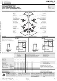
Positionierung der Betätigungsstange auf dem Türblatt<br />
6 Positioning the touchbar on the door leaf<br />
V4<br />
13<br />
58<br />
c<br />
V1<br />
40<br />
ø22<br />
V4<br />
V1<br />
V1<br />
H<br />
14 min<br />
V4<br />
40<br />
ø25<br />
V4<br />
a<br />
b<br />
80<br />
16 (41 max)<br />
81 L<br />
81<br />
d<br />
V1<br />
11<br />
135<br />
14<br />
H1<br />
58<br />
Bmax = 1050<br />
Zum fertigen Fußboden<br />
To the finished floor<br />
Zwingend erforderlich<br />
Urgently required<br />
(Fig.2)<br />
a.1<br />
a.1<br />
a.1<br />
G<br />
Fig.2<br />
G<br />
D+23<br />
35 min<br />
D+7<br />
34 min<br />
a.2<br />
X2<br />
X1<br />
y<br />
G<br />
D+7<br />
Das Maß D muss nach der Montage zwischen 9 mm und 12 mm liegen. Das Maß D darf nicht größer als 12 mm sein.<br />
Ist das Maß D größer 12 mm, darf die Betätigungsstange nicht montiert werden, da die Falle nicht ins Schließblech<br />
greift. Für einen einwandfreien Betrieb der Riegelsicherung muss der Abstand zwischen Schließblech und Riegel auf<br />
Null eingestellt werden (Maß G).<br />
Dimension D must be between 9 mm and 12 mm after the assembly. Dimension D may not be greater than 12 mm.<br />
If dimension D is greater than 12 mm, the touchbar may not be assembled, since the latch does not take a hold of the<br />
striking plate. The distance between the striking plate and the latch must be set at zero for a perfect locking operation<br />
(dimension G).<br />
D<br />
D<br />
X<br />
y<br />
HDE 19.06.2013 Maße in mm – Dimensions in mm<br />
8/16
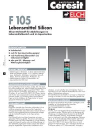
Kürzung von Stange, Verbindungstange und Haube<br />
7 Shortening the bar, connecting bar and cover<br />
HDE 19.06.2013 Maße in mm – Dimensions in mm<br />
H1-9<br />
H1+70<br />
H1<br />
H+16<br />
H+70<br />
H<br />
9/16
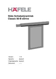
Einbauphasen<br />
8 Installation steps<br />
Nacheinander das Zentralschloss (1), die obere Falle (2) und die untere Falle (3) befestigen.<br />
Schließblech am Sturz (oberer Rahmen) befestigen (4).<br />
Install the central lock (1), the upper latch (2) and the lower latch (3) consecutively. Install the striking plate on<br />
the soffit (top frame) (4).<br />
16 (41 max)<br />
V1<br />
V1<br />
3<br />
V1<br />
1<br />
V1<br />
2<br />
Bei geschlossener Tür den unteren Spitzriegel in die Führung setzen (5) und in das Bodenschließblech fallen lassen.<br />
Place the lower shoot bolt into the guide (5) when the door is closed and let it drop into the floor socket.<br />
5<br />
Den oberen Spitzriegel in die Führung (6a) einfügen. Die Stange wie auf Abbildung (6b) ausrichten und ganz in den Spitzriegel<br />
einsetzen. Die Stange am Zentralschloss verbinden (6c). Die untere Stange ganz in den Spitzriegel einsetzen (7a) und sie am<br />
Zentralschloss verbinden (7b).<br />
V1<br />
V1<br />
V1<br />
11<br />
4<br />
V1 V1<br />
8a 8b<br />
8c<br />
Insert the upper shoot bolt into the guide (6a). Align the bar as shown in the figure (6b) and insert it completely into the shoot bolt.<br />
Connect the bar on the central lock (6c). Insert the lower bar completely into the shoot bolt (7a) and connect it on the<br />
central lock (7b).<br />
6a<br />
6c-7b<br />
CLIK<br />
6b<br />
6c<br />
CLIK<br />
CLIK<br />
7b<br />
7a<br />
HDE 19.06.2013 Maße in mm – Dimensions in mm<br />
10/16
Die Betätigungsstange (8a) ganz drücken, gedrückt halten und den oberen Spitzriegel (8b) in 1 mm Abstand zum Rand des<br />
oberen Schließblechs mit dem Stift befestigen. Die Stange loslassen.<br />
Completely push down the touchbar, continue to push and install the upper shoot bolt (8b) with pin at a distance of 1 mm to<br />
the edge of the top striking plate. Release the bar.<br />
8a<br />
8b<br />
Den unteren Spitzriegel aus dem Schließblech nehmen (9a) und ihn vorübergehend mit dem Stift an der Stange befestigen (9b).<br />
Remove the lower shoot bolt from the striking plate (9a) and temporarily attach it on the bar with the pin (9b).<br />
V3<br />
1<br />
8d 8e<br />
HDE 19.06.2013 Maße in mm – Dimensions in mm<br />
9a<br />
3<br />
10b<br />
9b 10a<br />
V3<br />
V3<br />
Die Betätigungsstange (10a) langsam und nur soweit drücken, bis die Tür öffnet. Den Flügel leicht öffnen (zirka 1 cm), die<br />
Betätigungsstange loslassen. Den Stift (10b) abschrauben. Den Spitzriegel (10b) in 3 mm Abstand zum Schließblechrand neu<br />
positionieren und befestigen. Die Betätigungsstange langsam und nur soweit drücken, dass die Tür öffnet. Prüfen, dass das<br />
Mindestspiel zwischen dem unteren Spitzriegel und dem Boden in allen Drehpunkten oberhalb von 3 mm bleibt.<br />
Slowly push the touchbar (10a) only so far until the door opens. Slightly open the door (approx. 1 cm), release the touchbar.<br />
Unscrew the pin (10b). Reposition and install the shoot bolt (10b) at a distance of 3 mm to the striking plate edge. Slowly push<br />
the touchbar only so far until the door opens. Check that the minimum play between the lower shoot bolt and the floor remains<br />
over 3 mm in all pivot points.<br />
8f<br />
11/16
Einbauphasen<br />
9 Installation phases<br />
Nacheinander das Zentralschloss (1), die obere Falle (2) und die untere Falle (3) befestigen.<br />
Install the central lock (1), the upper latch (2) and the lower latch (3) consecutively.<br />
9a<br />
16 (41 max)<br />
3<br />
1<br />
2<br />
11<br />
V1<br />
V1<br />
V1<br />
V1<br />
V1<br />
V1<br />
Bei geschlossener Tür den unteren Spitzriegel in die Führung setzen (4) und in das Bodenschließblech fallen lassen.<br />
Place the lower shoot bolt in the guide (4) when the door is closed and let it drop into the floor socket.<br />
9b<br />
4<br />
Den oberen Spitzriegel in die Führung (5a) einfügen. Die Stange wie auf Abbildung (5b) ausrichten und ganz in den Spitzriegel<br />
einsetzen. Die Stange am Zentralschloss verbinden (5c). Die untere Stange ganz in den Spitzriegel einsetzen (6a) und sie am<br />
Zentralschloss verbinden (6b).<br />
9c<br />
Insert the upper shoot bolt in the guide (5a). Align the bar as in the figure (5b) and completely insert into the shoot bolt.<br />
Connect the bar to the central lock (5c). Insert the lower bar completely in the shoot bolt (6a) and connect it on the central<br />
lock (6b).<br />
5c-6b<br />
CLIK<br />
5a<br />
5b<br />
5c<br />
CLIK<br />
CLIK<br />
6b<br />
6a<br />
HDE 19.06.2013 Maße in mm – Dimensions in mm<br />
12/16
Die Betätigungsstange (7a) ganz drücken, gedrückt halten und den oberen Spitzriegel (7b) in 1 mm Abstand zum Rand des<br />
oberen Schließblechs mit dem Stift befestigen. Die Stange loslassen.<br />
. Completely push down the touchbar (7a), continue to push it and install the upper shoot bolt (7b) at a 1 mm distance from<br />
the upper striking plate by using a pin. Release the bar.<br />
7a<br />
7b<br />
Den unteren Spitzriegel aus dem Schließblech nehmen (8a) und ihn vorübergehend mit dem Stift an der Stange befestigen (8b).<br />
Remove the lower shoot bolt from the striking plate (8a) and attach it temporarily to the bar by using the pin (8b).<br />
V3<br />
1<br />
9d 9e<br />
HDE 19.06.2013 Maße in mm – Dimensions in mm<br />
8a<br />
3<br />
9b<br />
8b V3<br />
V3<br />
Die Betätigungsstange (9a) langsam und nur soweit drücken, bis die Tür öffnet. Den Flügel leicht öffnen (zirka 1 cm),<br />
die Betätigungsstange loslassen. Den Stift (9b) abschrauben. Den Spitzriegel (9b) in 3 mm Abstand zum Schließblechrand<br />
neu positionieren und befestigen. Die Betätigungsstange langsam und nur soweit drücken, dass die Tür öffnet. Prüfen, dass<br />
das Mindestspiel zwischen dem unteren Spitzriegel und dem Boden in allen Drehpunkten oberhalb von 3 mm bleibt.<br />
Slowly push the touchbar (9a) only so far until the door opens. Slightly open the door (approx. 1 cm), release the touchbar.<br />
Unscrew the pin (9b). Reposition and install the shoot bolt (9b) at a distance of 3 mm from the striking plate edge. Slowly<br />
push the touchbar only so far until the door opens. Check that the minimum play between the lower shoot bolt and the floor<br />
remains above 3 mm in all pivot points.<br />
9a<br />
9f<br />
13/16
Montageanweisungen für verstellbares Schließblech<br />
10 Installation instructions for adjustable striking plates<br />
Montage auf Aluprofil mit Überhang von 0 bis 11 mm<br />
Installation on aluminum profile with a projection of 0 to 11 mm<br />
Montage auf PVC-Profil mit Überhang von 12 bis 23 mm<br />
Installation on PVC profile with a projection of 12 to 23 mm<br />
Montage auf komplanarem Eisenprofil mit Überhang von 0 bis 11 mm<br />
Installation on coplanar iron profile with a projection of 0 to 11 mm<br />
1<br />
Schließblechabdeckung aus lackiertem Zamak<br />
Striking plate cover of painted zinc alloy<br />
5<br />
2<br />
Am festen Rahmen zu verankernde Unterlegscheibe<br />
Adjustable accessory for coplanar windows and doors with<br />
projections of 0 to 11 mm<br />
6<br />
3<br />
Regulierbares Zubehör für komplanare Fenster und Türen mit<br />
Überhang von 0 bis 11 mm<br />
Adjustable element for coplanar doors and rebated doors<br />
(rebate from 0 to 11 mm)<br />
1 2<br />
3<br />
4<br />
4<br />
5<br />
6<br />
Regulierbares Zubehör für Fenster und Türen mit Überhang von<br />
12 bis 23 mm<br />
Adjustable accessory for windows and doors with projections of<br />
12 to 23 mm<br />
Schließblech für Deckenschließung<br />
Striking plate for ceiling lock<br />
Schließblech für Bodenschließung<br />
Striking plate for floor lock<br />
HDE 19.06.2013 Maße in mm – Dimensions in mm<br />
14/16
Öffnungsrichtung wählen<br />
11 Selecting the opening direction<br />
1<br />
2<br />
CLIK<br />
3<br />
SX<br />
DX<br />
Sichtbare Sperrvorrichtung -<br />
12 Visible latch retainer <strong>device</strong><br />
ZU/CLOSE<br />
OFFEN/OPEN<br />
135°<br />
H<br />
+ 56.5<br />
V1<br />
- 5<br />
0<br />
Filo telaio<br />
83<br />
-8<br />
0<br />
+8<br />
H1<br />
+ 56.5<br />
V1<br />
0<br />
V1<br />
V1<br />
58<br />
10<br />
V1<br />
V1<br />
V1<br />
V1<br />
10<br />
+ 27<br />
c<br />
a.1 (D=12)+23<br />
a.1 (D=9)+23<br />
a.2 (D=12)+7<br />
a.2 (D=9)+7<br />
0<br />
16<br />
0<br />
d<br />
0<br />
V1<br />
V1<br />
10<br />
V1<br />
V1<br />
58<br />
0<br />
10<br />
- 27<br />
-8<br />
0<br />
+8<br />
Bodenlinie<br />
Floor line<br />
H<br />
85.5<br />
HDE 19.06.2013 Maße in mm – Dimensions in mm<br />
- 44<br />
- 41<br />
- 28<br />
- 25<br />
H1<br />
V1<br />
a<br />
- 9.25<br />
0<br />
V1<br />
+ 9.25<br />
- 56.5<br />
L<br />
- 56.5<br />
V1<br />
- 9.25<br />
0<br />
b<br />
V1<br />
+ 9.25<br />
15/16
HDE 19.06.2013 Maße in mm – Dimensions in mm<br />
16/16<br />
Subject to<br />
alterations<br />
© 2013 by Häfele GmbH & Co KG<br />
Adolf-Häfele-Str. 1 · D-72202 Nagold · www.hafele.com