Indoor Dome Base CFVA-BA Mounting Instructions - Bewator Group
Indoor Dome Base CFVA-BA Mounting Instructions - Bewator Group
Indoor Dome Base CFVA-BA Mounting Instructions - Bewator Group

Sie wollen auch ein ePaper? Erhöhen Sie die Reichweite Ihrer Titel.
YUMPU macht aus Druck-PDFs automatisch weboptimierte ePaper, die Google liebt.
<strong>Indoor</strong> <strong>Dome</strong> <strong>Base</strong> <strong>CFVA</strong>-<strong>BA</strong><br />
<strong>Mounting</strong> <strong>Instructions</strong><br />
Type Designation Order No.<br />
<strong>CFVA</strong>-<strong>BA</strong> <strong>Indoor</strong> <strong>Dome</strong> <strong>Base</strong> 2GF1086-8AP<br />
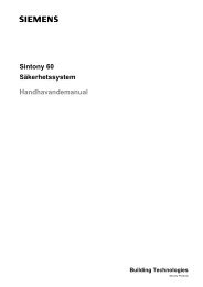
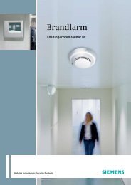
1 <strong>Dome</strong> base 11 Power connector (to twisted-pair transmitter)<br />
2 Hole plug 12, 13 Power connector (power supply)<br />
3 Plastic cover 14 Drilling template<br />
4 Fixing screws for the twisted-pair transmitter board 15 Expansion anchor<br />
5 Twisted-pair transmitter board (optional) 16 <strong>Mounting</strong> screws<br />
6 Cable entry holes 17 <strong>Mounting</strong> screws<br />
7 Two screws for fixing the camera 18 <strong>Indoor</strong> fix dome<br />
8 Mode setting DIP switches 19 Screws<br />
9 Twisted-pair transmitter terminal block 20 Cover<br />
10 Power connector (to camera)<br />
Fire Safety & Security Products<br />
Siemens Building Technologies
English<br />
About this document<br />
These instructions outline the most important<br />
information about the dome base. It is, however,<br />
vital that you also refer to the Instruction<br />
Manuals for <strong>Indoor</strong> <strong>Dome</strong> Camera and Twisted-<br />
Pair Transmitter CTTT0111.<br />
Product description<br />
This dome base is only designed for installation<br />
indoors and only for use in conjunction with a<br />
dome camera.<br />
Safety<br />
Warning<br />
To avoid electrical shock, do not<br />
open the cabinet. Refer servicing to<br />
qualified personnel only.<br />
To reduce the risk of fire or electrical<br />
shock, do not expose this product to<br />
rain or moisture.<br />
Please connect the equipment to a<br />
12 V DC UL Listed Class 2 power<br />
supply if this type of camera is to be<br />
installed.<br />
Target group<br />
These mounting instructions are only intended<br />
for use by installers who have an adequate<br />
working knowledge of video systems!<br />
This installation should be made by a qualified<br />
service person and should conform to all local<br />
codes.<br />
Operation and storage<br />
Do not operate or store the unit:<br />
• At extremely hot or cold places.<br />
• Close to sources of strong magnetism.<br />
• Close to sources of powerful electromagnetic<br />
radiation such as radios or TV transmitters.<br />
• At humid or excessively dusty places.<br />
• Where exposed to mechanical vibrations.<br />
• Close to fluorescent lamps or objects<br />
reflecting light.<br />
• Under unstable or flickering light sources<br />
Technical data<br />
Dimensions (H x dia.) 35.5 x 140 mm<br />
Weight<br />
200 g<br />
Material<br />
aluminium<br />
Details for ordering<br />
Type<br />
<strong>CFVA</strong>-<strong>BA</strong><br />
Order No. 2GF1086-8AP<br />
Designation <strong>Indoor</strong> dome base<br />
Type<br />
CTTT0111<br />
Order No. 2GF1714-8WN<br />
Designation Twisted-pair transmitter<br />
Scope of delivery<br />
• <strong>Indoor</strong> dome base<br />
• Plastic cover<br />
• 2 expansion anchors<br />
• 2 mounting screws<br />
• 2 mechanical screws<br />
• Power cable<br />
• Drilling template<br />
• <strong>Mounting</strong> instructions<br />
Installation<br />
1. Use the drilling template (14) to drill two<br />
holes in the wall (6 mm (1/4”) diameter and<br />
32 mm (1-1/4”) deep).<br />
2. Hammer an expansion anchor (15) into each<br />
hole just drilled.<br />
3. Decide which cable entry will be used.<br />
4. Attach dome base (1) to the wall using the<br />
mounting screws (16).<br />
5. If required, mount the twisted-pair transmitter<br />
(5) to the dome base using the screws<br />
supplied.<br />
6. Connect the video signal cable to terminals 5<br />
and 6 on the twisted-pair transmitter.<br />
IMPORTANT<br />
When using the twisted-pair<br />
transmitter, the indoor dome base<br />
must be supplied with<br />
12 V DC !<br />
7. Attach the indoor fix dome (18) to the dome<br />
base using two mechanical screws ((19)<br />
(see Fig. D).<br />
8. Turn the cover (20) clockwise to lock it to the<br />
camera (18).<br />
9. Attach the plastic cover (3) to the side of the<br />
indoor dome base.<br />
Setting the function<br />
1. Connecting the power cable (see Fig. C)<br />
10 Camera power<br />
11<br />
12<br />
TP transmitter<br />
power<br />
Power IN<br />
(Only DC+12V)<br />
Connect<br />
+ (red)<br />
GND(black)<br />
+ (red)<br />
GND(black)<br />
+ (red)<br />
GND(black)<br />
When using the optional twisted-pair transmitter:<br />
2. Connecting the terminal block (9)<br />
Function<br />
1 TP transmitter (b)<br />
2 TP transmitter (a)<br />
3 Power in (GND)<br />
4 Power in (Only +12V)<br />
5 Video in (GND)<br />
6 Video in (CVS)<br />
3. Setting the twisted-pair DIP switches (8).<br />
• Output voltage without accentuation<br />
S2<br />
S3<br />
2.0 Vpp Off Off<br />
2.6 Vpp On Off<br />
3.2 Vpp On On<br />
• Frequency-dependent accentuation<br />
S1<br />
S4<br />
Not frequency-dependent Off Off<br />
Approx. 6 dB with 5 MHz Off On<br />
Approx. 6 dB with 5 MHz On Off<br />
Approx.12dB with 5 MHz On On<br />
Disposal<br />
Electrical and electronic products<br />
should be disposed of separately<br />
from the municipal waste stream via<br />
designated collection facilities<br />
appointed by the government or the<br />
local authorities.<br />
Issued by<br />
Siemens Building Technologies<br />
Fire & Security Products GmbH & Co. oHG<br />
D-76181 Karlsruhe<br />
© 2006 Copyright by<br />
Siemens Building Technologies AG<br />
Data and design subject to change without notice.<br />
Supply subject to availability.<br />
www.sbt.siemens.com<br />
Document no.<br />
Edition 04.2006<br />
A24205-A336-H325
<strong>Dome</strong>-Sockel innen <strong>CFVA</strong>-<strong>BA</strong><br />
Montageanleitung<br />
Typ Bezeichnung Art. Nr.<br />
<strong>CFVA</strong>-<strong>BA</strong> <strong>Dome</strong>-Sockel innen 2GF1086-8AP<br />
1 <strong>Dome</strong>-Sockel 11 Netzanschluss (zum Zweidraht-Sender)<br />
2 Verschlussstopfen 12, 13 Netzanschluss (Spannungsversorgung)<br />
3 Kunststoffabdeckung 14 Bohrschablone<br />
4 Befestigungsschrauben für 2-Drahtsender 15 Spreizdübel<br />
5 2-Drahtsender (optional) 16 Montageschrauben<br />
6 Öffnungen für Kabeleinführung 17 Montageschrauben<br />
7 Schrauben zur Befestigung der Kamera 18 Innenraum-<strong>Dome</strong>-Kamera<br />
8 DIP-Schalter zur Funktionseinstellung 19 Schrauben<br />
9 Steckklemmenleiste des 2-Drahtsenders 20 Kuppel<br />
10 Netzanschluss (zur Kamera)<br />
Fire Safety & Security Products<br />
Siemens Building Technologies
Deutsch<br />
Zu diesem Dokument<br />
Hier finden Sie schnell die wichtigsten Informationen<br />
zu dem <strong>Dome</strong>-Sockel. Beachten Sie<br />
unbedingt auch die ausführliche Bedienungsanleitung<br />
für die Innenraum-<strong>Dome</strong>-Kamera und<br />
den Zweidraht-Sender CTTT0111.<br />
Produktbeschreibung<br />
Dieser <strong>Dome</strong>-Sockel ist ausschließlich zum<br />
Einsatz im Innenbereich und nur in Verbindung<br />
mit einer <strong>Dome</strong>-Kamera ausgelegt.<br />
Sicherheit<br />
Warnung<br />
Zur Vermeidung von Elektroschocks<br />
darf das Gehäuse nicht geöffnet<br />
werden. Servicearbeiten dürfen nur<br />
von qualifiziertem Personal ausgeführt<br />
werden.<br />
Um die Gefahr eines Brandes oder<br />
Elektroschocks zu verringern, darf<br />
dieses Gerät weder Regen noch<br />
Feuchtigkeit ausgesetzt werden.<br />
Zielgruppe<br />
Diese Montageanleitung ist nur für Fachpersonal<br />
vorgesehen, das mit der Videotechnik ausreichend<br />
vertraut ist!<br />
Die Installation sollte von qualifiziertem Wartungspersonal<br />
durchgeführt werden und muss<br />
den örtlichen Bestimmungen entsprechen.<br />
Betrieb und Lagerung<br />
Betreiben oder lagern Sie das Gerät nicht unter<br />
folgenden Bedingungen:<br />
• an extrem heißen oder kalten Orten<br />
• in der Nähe starker Magnetfelder<br />
• im Umfeld starker elektromagnetischer<br />
Strahlungsquellen wie Radios oder Fernsehsender<br />
• an feuchten oder extrem staubigen Orten<br />
• an Orten mit mechanischen Erschütterungen<br />
• in der Nähe von Leuchtstoffröhren oder Licht<br />
reflektierenden Objekten<br />
• unter unbeständigen oder flimmernden<br />
Lichtquellen<br />
Technische Daten<br />
Abmessungen (H x Ø) 35,5 x 140 mm<br />
Gewicht<br />
200 g<br />
Material<br />
Aluminium<br />
Bestellangaben<br />
Typ<br />
<strong>CFVA</strong>-<strong>BA</strong><br />
Art.-Nr. 2GF1086-8AP<br />
Bezeichnung <strong>Dome</strong>-Sockel innen<br />
Typ<br />
CTTT0111<br />
Art.-Nr. 2GF1714-8WN<br />
Bezeichnung Zweidraht-Sender<br />
Lieferumfang<br />
• <strong>Dome</strong>-Sockel innen<br />
• Kunststoffabdeckung<br />
• 2 Spreizdübel<br />
• 2 Montageschrauben<br />
• 2 mechanische Schrauben<br />
• Netzkabel<br />
• Bohrschablone<br />
• Montageanleitung<br />
Montage<br />
1. Markieren Sie mit Hilfe der Bohrschablone<br />
(14) zwei Bohrlöcher und bohren Sie diese<br />
(6 mm Durchmesser, 32 mm tief).<br />
2. Schlagen Sie in jedes Loch einen Spreizdübel<br />
(15) ein.<br />
3. Legen Sie fest, wie die Kabel eingeführt<br />
werden sollen.<br />
4. Befestigen Sie den <strong>Dome</strong>-Sockel (1) mit<br />
Hilfe der Montageschrauben (16).<br />
5. Befestigen Sie gegebenenfalls den Zweidraht-Sender<br />
(5) mit Hilfe der mitgelieferten<br />
Schrauben auf dem <strong>Dome</strong>-Sockel.<br />
6. Schließen Sie das Videokabel an den Anschlussklemmen<br />
5 und 6 des Zweidraht-<br />
Senders an.<br />
Achtung<br />
Bei Verwendung des Zweidraht-<br />
Senders muss die Spannungsversorgung<br />
des <strong>Dome</strong>-Sockels mit<br />
12 V DC erfolgen!<br />
7. Befestigen Sie die Innenraum-<strong>Dome</strong>-Kamera<br />
(18) mit Hilfe der zwei mechanischen<br />
Schrauben (19) am <strong>Dome</strong>-Sockel (siehe<br />
Abb. D).<br />
8. Drehen Sie die Kuppel (20) im Uhrzeigersinn,<br />
bis sie im Kameragehäuse (18) einrastet.<br />
9. Setzen Sie die Kunststoffabdeckung (3)<br />
seitlich am <strong>Dome</strong>-Sockel ein.<br />
Einstellung der Funktionen<br />
1. Anschluss des Netzkabels (siehe Abb. C)<br />
10<br />
11<br />
12<br />
Spannungsversorgung<br />
der<br />
Kamera<br />
Anschluss von<br />
Spannungsversorgung<br />
Zweidraht-Sender<br />
Power IN<br />
(nur DC +12V)<br />
+ (rot)<br />
GND (schwarz)<br />
+ (rot)<br />
GND (schwarz)<br />
+ (rot)<br />
GND (schwarz)<br />
Bei Verwendung des optionalen Zweidraht-<br />
Senders:<br />
2. Anschluss der Klemmenleiste (9)<br />
Funktion<br />
1 Zweidraht-Sender (b)<br />
2 Zweidraht-Sender (a)<br />
3 Power IN (GND)<br />
4 Power IN (nur +12V)<br />
5 Video IN (GND)<br />
6 Video IN (<strong>BA</strong>S)<br />
3. Einstellen der DIP-Schalter (8) des Zweidraht-Senders<br />
• Ausgangsspannung ohne Anhebung<br />
S2<br />
S3<br />
2,0 Vss Aus Aus<br />
2,6 Vss Ein Aus<br />
3,2 Vss Ein Ein<br />
• Frequenzabhängige Anhebung<br />
S1<br />
S4<br />
Nicht frequenzabhängig Aus Aus<br />
Ca. 6 dB bei 5 MHz Aus Ein<br />
Ca. 6 dB bei 5 MHz Ein Aus<br />
Ca. 12 dB bei 5 MHz Ein Ein<br />
Entsorgung<br />
Alle Elektro- und Elektronikgeräte<br />
sind getrennt vom allgemeinen<br />
Hausmüll über dafür staatlich vorgesehene<br />
Stellen zu entsorgen.<br />
Herausgegeben von<br />
Siemens Building Technologies<br />
Fire & Security Products GmbH & Co. oHG<br />
D-76181 Karlsruhe<br />
© 2006 Copyright by<br />
Siemens Building Technologies AG<br />
Liefermöglichkeiten und technische Änderungen vorbehalten.<br />
www.sbt.siemens.com<br />
Dokument Nr.<br />
Ausgabe 04.2006<br />
A24205-A336-H325