LGB 21900 DUO-Diesellok
LGB 21900 DUO-Diesellok
LGB 21900 DUO-Diesellok

Sie wollen auch ein ePaper? Erhöhen Sie die Reichweite Ihrer Titel.
YUMPU macht aus Druck-PDFs automatisch weboptimierte ePaper, die Google liebt.
<strong>LGB</strong> <strong>21900</strong> <strong>DUO</strong>-<strong>Diesellok</strong><br />
<strong>LGB</strong> <strong>21900</strong> <strong>DUO</strong>-<strong>Diesellok</strong><br />
Die hier beschriebenen Änderungen erfolgen auf eigenes Risiko !<br />
Home Gartenbahn Umbauten<br />
Inhalt<br />
Schema<br />
Decoder-Einbau<br />
Programmierung<br />
Hinweis: Sie können bei allen Fotos eine bessere Version betrachten. Klicken Sie einfach auf das Bild.<br />
Schema<br />
Als Grundlage für meinen Umbau diente mir das folgende Schema:<br />
http://www.beathis.ch/lgb/<strong>21900</strong>/<strong>21900</strong>.html<br />
18/09/09 8:07 AM<br />
Page 1 of 5
<strong>LGB</strong> <strong>21900</strong> <strong>DUO</strong>-<strong>Diesellok</strong><br />
Schema als PDF-Dokument.<br />
http://www.beathis.ch/lgb/<strong>21900</strong>/<strong>21900</strong>.html<br />
18/09/09 8:07 AM<br />
Ich verwendete den Decoder Loksound XL von ESU. Ich wollte die Original-5V-Lampen belassen und schaltete daher<br />
die Widerstände R1..R5 dazwischen. Die genauen Ohm-Werte müssen ev. angepasst werden. Der Decoder lieferte auf<br />
meiner Digitrax-Anlage an den Funktionsausgängen 18V. Eine 5V-Lampe verbraucht ca. 35mA bei normaler Helligkeit.<br />
Die Entkuppler-Motoren laufen erst mit 8V einwandfrei. Ein Versuch mit 5V zeigte, dass dann die Mechanik nicht bis in<br />
die Endstellungen lief. Es ist zu beachten, dass bei häufigem, aufeinanderfolgendem Schalten der IC U2 ziemlich heiss<br />
werden kann ! Der Schalter S1 wird benötigt, um die Entkupplermotoren abzuschalten. Der ESU-Lokprogrammer liefert<br />
im Decodertest zuwenig Strom dafür.<br />
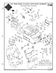
Teil Beschreibung Bezugsquelle Artikel-<br />
Nr.<br />
D1 Diode 1N4148 75V Distrelec (CH) 60 30 16<br />
RL1 Klein-Relais 24V 1x Umschalter Distrelec (CH) 40 25 34<br />
C1 Elko 100uF 63V Distrelec (CH) 80 04 45<br />
C2 Kondensator 0.1uF 63V Distrelec (CH) 82 18 46<br />
R1,R2 Widerstand 120 Ohm Distrelec (CH) 70 02 14<br />
R3,R4,R5 Widerstand 330 Ohm Distrelec (CH) 70 02 19<br />
U1 Brückengleichrichter B40C800 I=0.8A U=40V Distrelec (CH) 60 00 05<br />
U2<br />
Spannungsregler LM2940T-8 "Low-Dropout" Iout=0.5A Uout=8V<br />
Gehäuse=TO-220<br />
Distrelec (CH) 64 53 94<br />
S1 Schalter 1polig ON-ON Distrelec (CH) 20 20 00<br />
- Loksound XL Decoder "<strong>Diesellok</strong>"<br />
ESU Loksound<br />
(D)<br />
-<br />
Page 2 of 5
<strong>LGB</strong> <strong>21900</strong> <strong>DUO</strong>-<strong>Diesellok</strong><br />
- Lautsprecher 40mm<br />
Zum Anfang<br />
Decoder-Einbau<br />
http://www.beathis.ch/lgb/<strong>21900</strong>/<strong>21900</strong>.html<br />
ESU Loksound<br />
(D)<br />
18/09/09 8:07 AM<br />
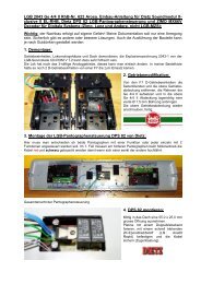
Diese Lok ist noch nicht mit einer sog. Digital-Schnittstelle ausgerüstet. Somit muss<br />
der 2. Motoranschluss in die Kabine gezogen werden. Zuerst trennt man den<br />
Antrieb vom Gehäuse und öffnet den Antrieb oben. Nun kann der Motor<br />
herausgenommen werden und ein Kabel (im Bild links blau) am 2. Anschluss<br />
angelötet werden. In den Deckel bohrte ich ein Loch und führte das Kabel hindurch.<br />
Ich plazierte im Fahrwerk unter der Kabine Zusatzgewichte. Hierzu verwendete ich<br />
Bleistücke (Artikel 46068 und 46069) von Old Pullman (CH).<br />
Auch in den beiden Boxen vorne am Fahrwerk klebte ich Bleistücke ein.<br />
Für den Lautsprecher (Durchmesser 40mm von ESU) machte ich eine Öffnung im<br />
Fahrpult der Kabine.<br />
-<br />
Page 3 of 5
<strong>LGB</strong> <strong>21900</strong> <strong>DUO</strong>-<strong>Diesellok</strong><br />
Zum Anfang<br />
Programmierung<br />
http://www.beathis.ch/lgb/<strong>21900</strong>/<strong>21900</strong>.html<br />
Ich klebte dann den Lautsprecher mit einem 2-Komponenten-Epoxikleber fest.<br />
18/09/09 8:07 AM<br />
Auf das Originalgewicht klebte ich mit Doppelklebband zuerst die Original-<strong>LGB</strong>-<br />
Metallplatte und dann eine dünne Polysterol-Platte für die Isolierung. Im hinteren<br />
Teil des Motorgehäuses befestigte ich meine Zusatzplatine. Dort wurden die<br />
Original-<strong>LGB</strong>-Flachbandkabel angeschlossen. Im vorderen Teil klebte ich den<br />
Decoder mit einem Doppelklebband fest.<br />
Nun war der Umbau bereits abgeschlossen, es fehlte nur noch die Programmierung<br />
des Decoders.<br />
Der Loksound XL Decoder ist sehr komplex, da er neben dem Decoder auch ein<br />
Soundmodul enthält. Mit der klassischen Decoder-Programmierung über die CVs<br />
kann ich zwar alle Decodereinstellungen verändern, nicht aber die<br />
Soundsequenzen. Aus diesem Grund kaufte ich den "Lokprogrammer" von ESU.<br />
Zum Lieferumfang gehören: Interface (siehe Bild links), Netzteil, serielles PC-Kabel<br />
und die Windows-Software.<br />
Bei der Software empfiehlt sich ein Blick auf die ESU Homepage. Dort findet man<br />
die neuste Version des Lokprogrammers.<br />
Der wichtigste Teil bei der Programmierung ist die Zuordnung der<br />
Funktionsausgänge (auch Function Mapping). Das nebenstehende Bild (klicken Sie<br />
auf das Bild für eine bessere Auflösung) zeigt die entsprechende Bildschirmmaske.<br />
Für das obige Schema werden mit der Funktion F1 die Ausgänge AUX1 (Relais),<br />
AUX2 (Lampe gelb) und AUX3 (Lampe rot) eingeschaltet. Zusammen mit dem Licht<br />
(beide Richtungen) wird der Ausgang AUX4 aktiviert. Bei allen Ausgängen setzte<br />
ich die Helligkeit auf den Maximalwert. Damit die beiden Lampen auf dem Dach<br />
wechselweise blinken, setzte ich AUX2 auf "Blinklicht" und AUX3 auf "Blinklicht<br />
negiert". Die Blink-Geschwindigkeit setzte ich auf 1.1 Sekunden.<br />
Dieser Teil der Programmierung kann auch direkt mit den CVs gemacht werden.<br />
Interessant ist die Möglichkeit, die Soundsequenzen und Reihenfolgen mit dem<br />
Lokprogrammer zu verändern. Das nebenstehende Bild (klicken Sie auf das Bild für<br />
eine bessere Auflösung) zeigt die entsprechende Bildschirmmaske.<br />
Der Decoder kann insgesamt 11.4 Sekunden Sound speichern. Die einzelnen<br />
Sequenzen (Dieselmotor anlassen, Dieselmotor im Leerlauf, ...) sind nur sehr kurz<br />
und werden teilweise endlos wiederholt. So kann man trotz des knappen Speichers<br />
einiges machen.<br />
Zusätzlich kann man Soundsequenzen auch direkt Funktionstasten zuordnen. Das<br />
Page 4 of 5
<strong>LGB</strong> <strong>21900</strong> <strong>DUO</strong>-<strong>Diesellok</strong><br />
Zum Anfang<br />
© 2006 by This Manhart - Letzte Änderung: 06.04.2006<br />
http://www.beathis.ch/lgb/<strong>21900</strong>/<strong>21900</strong>.html<br />
18/09/09 8:07 AM<br />
nebenstehende Bild (klicken Sie auf das Bild für eine bessere Auflösung) zeigt die<br />
entsprechende Bildschirmmaske.<br />
Zwischen den Soundslots und den Funktionsausgängen bestehen abhängigkeiten !!<br />
Page 5 of 5
<strong>LGB</strong> <strong>21900</strong> <strong>DUO</strong>-Diesel Engine<br />
<strong>LGB</strong> <strong>21900</strong> <strong>DUO</strong>-Diesel Engine<br />
All modifications described herein are done at your own risk !<br />
Home Garden Railway Conversions<br />
Contents<br />
Schematic<br />
Decoder Installation<br />
Programming<br />
Note: You can view all pictures in a larger version, simply click on it.<br />
Schematic<br />
The following schematic was used as the basis for this conversion:<br />
http://www.beathis.ch/lgb/<strong>21900</strong>/<strong>21900</strong>_e.html<br />
18/09/09 8:07 AM<br />
Page 1 of 5
<strong>LGB</strong> <strong>21900</strong> <strong>DUO</strong>-Diesel Engine<br />
Schematic as a PDF-Document.<br />
http://www.beathis.ch/lgb/<strong>21900</strong>/<strong>21900</strong>_e.html<br />
18/09/09 8:07 AM<br />
I used the decoder Loksound XL from ESU. I wanted to keep the original 5 volt lamps and therefore added resistors<br />
R1..R5 in series. The exact values may have to be adjusted somewhat. With my particular Digitrax system, the decoder<br />
provides 18 volts at the function outputs. A 5 volt lamp draws about 35ma at normal brightness.<br />
The motors for the uncoupling mechanism require at least 8 volts to operate properly. When using 5 volts, the<br />
mechanism would not move completely to its final end position. It should be noted that IC U2 becomes quite hot if you<br />
operate the coupler several times in quick succession! Switch S1 is required to shut off the uncoupling motors. The<br />
ESU-Locoprogrammer does not provide sufficient current for this during the decoder test.<br />
Designation Description Source Article<br />
Number<br />
D1 Diode 1N4148 75V Distrelec (CH) 60 30 16<br />
RL1 Miniature Relay 24V 1C (Transfer) Contact Distrelec (CH) 40 25 34<br />
C1 Electrolytic Capacitor 100uF 63V Distrelec (CH) 80 04 45<br />
C2 Capacitor 0.1uF 63V Distrelec (CH) 82 18 46<br />
R1,R2 Resistor 120 Ohm Distrelec (CH) 70 02 14<br />
R3,R4,R5 Resistor 330 Ohm Distrelec (CH) 70 02 19<br />
U1 Bridge Rectifier B40C800 I=0.8A U=40V Distrelec (CH) 60 00 05<br />
U2<br />
Voltage Regulator LM2940T-8 "Low-Dropout" Iout=0.5A Eout=8V<br />
Case =TO-220<br />
Distrelec (CH) 64 53 94<br />
S1 Switch Single pole ON-ON Distrelec (CH) 20 20 00<br />
- Loksound XL Decoder "Diesel Engine"<br />
ESU Loksound<br />
(D)<br />
-<br />
Page 2 of 5
<strong>LGB</strong> <strong>21900</strong> <strong>DUO</strong>-Diesel Engine<br />
- Speaker 40mm<br />
Top<br />
Decoder Installation<br />
http://www.beathis.ch/lgb/<strong>21900</strong>/<strong>21900</strong>_e.html<br />
ESU Loksound<br />
(D)<br />
-<br />
18/09/09 8:07 AM<br />
This engine is not equipped with a so called decoder interface. One therefore has<br />
to bring the second motor connection into the housing. First, you separate the motor<br />
block from the housing and open the top of the motor block. Now you can lift out<br />
the motor and a wire (blue in the photo on the left) can be soldered to the second<br />
motor connection I drilled a hole in the motor cover to feed the wire through.<br />
I added additional weights in the drive train under the cab. For this I used lead<br />
pieces (items 46068 and 46069) from Old Pullman (Switzerland).<br />
I also glued lead pieces inside the two boxes at the front of the chassis.<br />
To accommodate the speaker, (diameter 40mm, provided by ESU) I cut an opening<br />
into the control panel of the cab.<br />
Page 3 of 5
<strong>LGB</strong> <strong>21900</strong> <strong>DUO</strong>-Diesel Engine<br />
Zum Anfang<br />
Programming<br />
http://www.beathis.ch/lgb/<strong>21900</strong>/<strong>21900</strong>_e.html<br />
I then fastened the speaker using 2-component epoxy glue.<br />
18/09/09 8:07 AM<br />
On top of the original weight, I first fastened the Original-<strong>LGB</strong>-metalplate using<br />
double-sided tape and then a thin plastic sheet to provide insulation.. My additional<br />
circuit board was fastened in the rear section of the motor housing. There I<br />
attached the original <strong>LGB</strong> ribbon cable. The decoder was fastened in the front part<br />
of the housing using double-sided tape.<br />
The digital conversion was now complete, all that was left to do was the<br />
programming of the decoder.<br />
The Loksound XL Decoder is very complex, since there is an integrated sound<br />
module within the decoder. Using the normal programming methods via CVs, I<br />
could modify all of the decoder settings, but not the sound parameters. I therefore<br />
had to purchase the ESU "Lokprogrammer". Included in that package is the<br />
following: Interface (picture at left), power supply, PC cable for the serial port and<br />
the Windows-Software.<br />
For the software it is recommended that you check the ESU Homepage. There you<br />
will find the latest version of the "Lokprogrammer".<br />
The most important part of programming is the function mapping. The adjacent<br />
picture (click on the picture for a higher resolution one) shows the relevant screen<br />
shot.<br />
Per the above schematic, function button F1 will switch the following outputs: AUX1<br />
(Relay), AUX2 (yellow lamp) and AUX3 (red lamp). Together with the light (both<br />
directions), output AUX4 is activated. I programmed the brightness for all outputs at<br />
maximum. To flash both lights on the roof alternately, I programmed AUX2 to<br />
"Blinklicht" and AUX3 to "Blinklicht negiert". The flashing rate was set to 1.1<br />
seconds.<br />
This part of the programming can also be done directly using CVs.<br />
Particularly interesting is the possibility to modify the sound parameters and their<br />
sequence using the ESU Lokprogrammer. The adjacent picture (click on the picture<br />
for a higher resolution one) shows the relevant screen shot.<br />
The decoder can store a total of 11.4 seconds of sound. The individual sounds<br />
(starting the diesel engine, diesel engine idling, ...) are very short and are being<br />
repeated indefinitely as required. Thus, even with the decoders limited memory,<br />
reasonable sound effects can be created.<br />
In addition, one can also assign the sound effects directly to the function buttons.<br />
Page 4 of 5
<strong>LGB</strong> <strong>21900</strong> <strong>DUO</strong>-Diesel Engine<br />
Zum Anfang<br />
© 2002 by This Manhart - Letzte Änderung: 21.January 2002<br />
http://www.beathis.ch/lgb/<strong>21900</strong>/<strong>21900</strong>_e.html<br />
18/09/09 8:07 AM<br />
The adjacent picture (click on the picture for a higher resolution one) shows the<br />
relevant screen shot.<br />
Note that there are interdependencies between the sound 'slots' and the function<br />
outputs !!<br />
Page 5 of 5