Bedienungsanleitung - Electrolux-ui.com
Bedienungsanleitung - Electrolux-ui.com
Bedienungsanleitung - Electrolux-ui.com

Sie wollen auch ein ePaper? Erhöhen Sie die Reichweite Ihrer Titel.
YUMPU macht aus Druck-PDFs automatisch weboptimierte ePaper, die Google liebt.
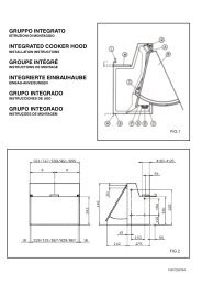
3. Wiring diagram with automatic ignition and no interior light<br />
Battery connection 12V/24V -<br />
A = Ground heating element DC, white<br />
B = Heating element DC-, red<br />
C = Ground automatic ignition, black<br />
D = Automatic ignition violet<br />
4. Wiring diagram with automatic ignition and interior light<br />
Battery connection 12V/24V -<br />
A = Ground heating element DC, white<br />
B = Heating element DC-, red<br />
C = Ground, automatic ignition black<br />
and interior light,<br />
D = Automatic ignition and violet<br />
interior light<br />
* resistor (replaced by a bridge for 24V battery voltage)<br />
heating-element DC -<br />
heating-element DC -<br />
ground<br />
heatingelement<br />
AC~<br />
29<br />
battery connection<br />
12V/24V --<br />
thermo cut-off current<br />
thermo cut-off current<br />
to casing<br />
spark plug<br />
spark plug<br />
light DC --<br />
reigniter<br />
ground ignition control lamp<br />
heatingelement<br />
AC~<br />
battery connection<br />
12V/24V --<br />
* resistor<br />
to casing<br />
to casing<br />
to casing<br />
from battery<br />
from battery<br />
ignition control lamp<br />
mains connection ~<br />
reed contacts<br />
(sensor switching)<br />
mains connection ~<br />
to casing