PDF öffnen
PDF öffnen
PDF öffnen

Sie wollen auch ein ePaper? Erhöhen Sie die Reichweite Ihrer Titel.
YUMPU macht aus Druck-PDFs automatisch weboptimierte ePaper, die Google liebt.
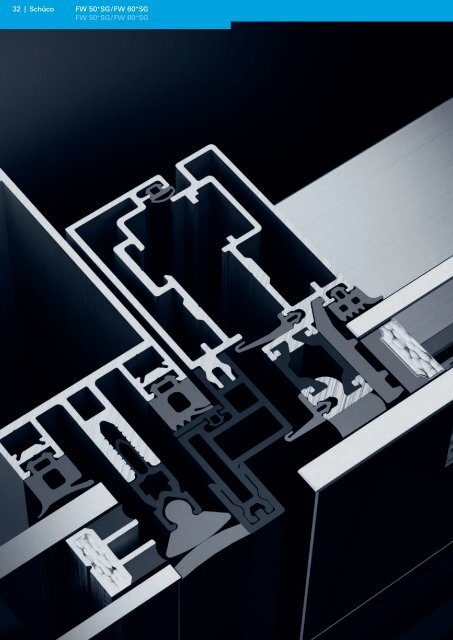
32 | Schüco<br />
FW 50 + SG / FW 60 + SG<br />
FW 50 + SG / FW 60 + SG
Test certificates<br />
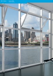
Fassadensystem FW 50 + SG / FW 60 + SG<br />
Façade systems FW 50 + SG / FW 60 + SG<br />
Die Fassadensysteme FW 50 + SG<br />
und FW 60 + SG basieren auf den<br />
bewährten Fassendensystemen<br />
FW 50 + und FW 60 + . Spezielle<br />
Einsatzelemente und Glasdetails<br />
ermöglichen den Einsatz als<br />
Ganzglasfassade. Die Anwendungsmöglichkeiten<br />
sind mit<br />
denen der Basissysteme<br />
FW 50 + / FW 60 + nahezu<br />
identisch, so lassen sich außer<br />
geraden Fassaden auch segmentierte<br />
Konstruktionen und<br />
einfache Lichtdächer realisieren.<br />
The FW 50 + SG and FW 60 + SG<br />
façade systems are based on the<br />
tried-and-tested FW 50 + and<br />
FW 60 + façade systems. Special<br />
insert units and glazing features<br />
allow it to be used as structural<br />
glazing. These options are<br />
practically identical to the<br />
FW 50 + / FW 60 + basic systems<br />
options which offer not only<br />
vertical but also faceted façade<br />
designs and simple skylights.<br />
FW 50 + SG / FW 60 + SG<br />
FW 50 + SG / FW 60 + SG<br />
34 Systemeigenschaften<br />
System features<br />
36 Prüfzeugnisse<br />
Test certificates<br />
37 Technische Werte<br />
Technical values<br />
39 Konstruktionsprinzipien<br />
Construction principles<br />
48 Anwendungsbeispiele<br />
Examples<br />
66 Profilübersicht<br />
Summary of profiles<br />
Schüco | 33<br />
FW 60 + SG<br />
FW 50 + SG
34 | Schüco<br />
Maßstab 1:1<br />
Scale 1:1<br />
Systemeigenschaften<br />
System features<br />
FW 50 + SG / FW 60 + SG<br />
Eigenschaften und Vorteile<br />
Alle Systemkomponenten der Fassaden-<br />
Konstruktion FW 50 + / FW 60 + können eingesetzt<br />
werden.<br />
Die Fassade FW 60 + SG ist für höhere Glaslasten<br />
bis 350 – 450 kg (je nach Verglasung) geeignet.<br />
Voraussetzung dafür ist, dass alle Parameter wie<br />
z. B. Tragwerk, T-Verbindung, Glasträger und<br />
Silikonverklebung darauf ausgelegt sind.<br />
Für das System FW 50 + SG liegt eine europäisch<br />
technische Zulassung vor.<br />
Das System kann bis zu einer Gebäudehöhe von<br />
100 m eingesetzt werden. (1)<br />
•<br />
•<br />
•<br />
•<br />
Optische Gestaltungsvarianten<br />
Ganzglas-Fassade<br />
Fugenausbildung mit flächenbündiger<br />
Trockenverglasung<br />
Fugenausbildung mit U-förmiger<br />
Trockenverglasung<br />
Fugenausbildung mit Nassversiegelung<br />
Zweiseitige Halterung<br />
mit vertikalen Deckschalen<br />
mit horizontalen Deckschalen<br />
Stoßfugenbreite 20 mm<br />
Glaseinstand<br />
FW 50 + SG: 15 mm<br />
FW 60 + •<br />
•<br />
•<br />
•<br />
•<br />
•<br />
•<br />
•<br />
•<br />
•<br />
• SG: 20 mm<br />
• Glasdicken innen und außen jeweils<br />
6, 8, 10, 12 oder 14 mm<br />
• Verdecktliegende Befestigung der Isolierglas-<br />
Festfelder mit Glashaltern<br />
Einsatzelemente<br />
• Schüco AWS 102 oder Schüco AWS 102.NI<br />
wahlweise als Senkklapp- oder Parallel-<br />
Ausstell-Fenster<br />
•<br />
Die Einsatzelemente können wahlweise handoder<br />
motorbetätigt werden.<br />
(1) Die Beschränkung der Einbauhöhe von Structural Glazing-Fassaden unterliegt in<br />
der Regel nationalen und/oder lokalen Bestimmungen (z. B. in Deutschland ohne<br />
zusätzliche mechanische Sicherung bis max. 8 m Einbauhöhe). Für weiterführende<br />
Informationen wenden Sie sich bitte an Ihre Schüco Niederlassung oder<br />
schicken eine E-Mail mit Ihrer Frage an: sg-service@schueco.com
Maßstab 1:1<br />
Scale 1:1<br />
Systemeigenschaften<br />
System features<br />
Features and benefits<br />
All system components for the façade<br />
construction FW 50 + / FW 60 + can be used.<br />
The FW 60 + SG façade is suitable for higher glass<br />
loads up to 350 – 450 kg (depending on glazing).<br />
All parameters such as load-bearing structure,<br />
T-joints, glazing supports and silicone adhesive<br />
must be designed accordingly.<br />
A European Technical Approval is available for the<br />
FW 50 + SG system.<br />
The system can be used for building heights of up<br />
to 100 m. (1)<br />
•<br />
•<br />
•<br />
•<br />
Different design options<br />
Structural glazing<br />
Joint configuration using flush-fitted dry<br />
glazing<br />
Joint with U-shaped dry glazing<br />
Joint using wet sealing<br />
Fixing on two sides<br />
With vertical cover caps<br />
With horizontal cover caps<br />
Butt joint width 20 mm<br />
Glass edge cover<br />
FW 50 + SG: 15 mm<br />
FW 60 + •<br />
•<br />
•<br />
•<br />
•<br />
•<br />
•<br />
•<br />
•<br />
•<br />
• SG: 20 mm<br />
• Internal and external glass thicknesses of 6, 8, 10,<br />
12 or 14 mm<br />
• Concealed fixing lugs for attaching double glazed<br />
fixed lights with glazing clips.<br />
Insert units<br />
• Schüco AWS 102 or Schüco AWS 102.NI either<br />
as parallel-opening windows or projected<br />
top-hung windows.<br />
• The insert units can be operated manually or by<br />
motor.<br />
(1) The installation height of structural glazing façades is generally restricted in<br />
order to comply with national or local requirements (e.g. in Germany, an<br />
installation height of up to 8 m without additional mechanical fixing). Contact<br />
your local Schüco office for more information or e-mail us with your questions at:<br />
sg-service@schueco.com<br />
Schüco | 35<br />
FW 60 + SG<br />
FW 50 + SG
36 | Schüco<br />
Prüfzeugnisse<br />
Test certificates<br />
Prüfzeugnisse<br />
Test certificates<br />
System<br />
System<br />
FW 50 + SG<br />
FW 50 + SG<br />
[FW 60 + SG]<br />
FW 50 + SG<br />
FW 60 + SG<br />
Art der Prüfung<br />
Type of test<br />
Fugendurchlässigkeit<br />
Air permeability<br />
Schlagregendichtheit<br />
Watertightness<br />
Isolierglasprüfung<br />
Double glazing<br />
Europäisch-technische Zulassung (ETA)<br />
European Technical Approval<br />
regulations (ETA)<br />
Allgemeine bauaufsichtliche Zulassung<br />
General building approval<br />
Absturzsicherheit<br />
Safety barrier<br />
Luftschalldämmung<br />
Airborne sound insulation<br />
Uf-Wert Uf value<br />
Air, Water, Structural Seismic<br />
Interstory Movement<br />
Air, Water, Structural Seismic<br />
Interstory Movement<br />
Hinweis:<br />
Für das System FW 50 + SG liegt eine europäisch<br />
technische Zulassung nach ETA 002 vor. Für das<br />
System FW 60 + SG ist eine Zustimmung im Einzelfall<br />
zu beantragen!<br />
Grundlage<br />
Basis<br />
EN 12152<br />
EN 12154<br />
Prüfinstitut<br />
Test institute<br />
ift Rosenheim<br />
Nr. des Prüfzeugnisses/<br />
Bescheids<br />
No. of the test certificate /<br />
certificate<br />
105 25509<br />
108 31193<br />
prEN1279-2 601 25611/1<br />
ETAG 002<br />
Deutsches Institut für<br />
Bautechnik<br />
05/0114<br />
– Z-70.1-46<br />
E-TRAV<br />
EN 12600<br />
EN 20140-3:<br />
1995-01<br />
EN ISO 717-1:<br />
1996-12<br />
–<br />
PSP RWTH Aachen S-47-01<br />
ift Rosenheim<br />
161 26794/1.0.0<br />
161 26794/2.0.0<br />
432 28487/1<br />
432 28487/2<br />
AAMA 501-05<br />
56821.02-120-47-RO<br />
ATI<br />
AAMA 501-05 58438.01-122-34<br />
Note:<br />
An European Technical Approval is available for the<br />
FW 50 + SG system in accordance with ETA 002. For the<br />
FW 60 + SG system, project-based approval is required.<br />
Prüfergebnis<br />
Test result<br />
AE 1200 PA<br />
AE<br />
RE 1050 PA<br />
RE 1200 PA<br />
positiv<br />
Positive<br />
erteilt<br />
Issued<br />
voll absturzsichernd Kategorie A<br />
Category A, fully protected<br />
R w (C; C tr ) = 38 (-1; -3) dB<br />
R w (C; C tr ) = 44 (-2; -5) dB<br />
U f = 2,2 - 2,8 W/m 2 K<br />
U f = 1,6 - 1,8 W/m 2 K<br />
PA 1436<br />
psF 30
Wärmedämmung<br />
Thermal insulation<br />
Flächenbündige Trockenverglasung<br />
Flush-fitted dry glazing<br />
Maßstab 1:2<br />
Scale 1:2<br />
FW 50 + SG gezeichnet / FW 60 + SG sinngemäß<br />
FW 50 + SG shown / similar principles for FW 60 + SG<br />
FW 50 + SG / FW 60 + SG<br />
Hinweis:<br />
Diese Werte sind geeignet, die Anforderungen der<br />
Energieeinsparverordnung EnEV 2002 in Deutschland<br />
oder des Document L in England und Wales,<br />
vollständig zu erfüllen (in Verbindung mit geeigneten<br />
Gläsern, Baukörperanschlüssen und der richtigen<br />
Ausfachung). Eine definitive Beurteilung kann meist<br />
nur erfolgen, wenn ganze Bauteile oder das gesamte<br />
Bauwerk berechnet werden.<br />
*Diese U f -Werte sind nach der<br />
E DIN EN ISO 10077-2 berechnet.<br />
x<br />
U-förmige Trockenverglasung<br />
U-shaped dry glazing<br />
mm mm<br />
32 - 48 50 - 250<br />
Note:<br />
These values are fully compliant with the<br />
requirements of the EnEV 2002 energy saving<br />
regulations in Germany and Document L in England<br />
and Wales (when used in conjunction with suitable<br />
glass, attachments to structure and the correct infill<br />
panels). To obtain a definitive evaluation, you usually<br />
need to use calculations for complete building<br />
components or the entire construction/building.<br />
*These U f values have been calculated in accordance<br />
with E DIN EN ISO 10077-2.<br />
Technische Werte<br />
Technical values<br />
Silikonfugen mit Nassversiegelung<br />
Silicone joints with wet sealing<br />
W/m 2 K<br />
FW 50 + SG FW 60 + SG<br />
2,1 - 1,7 1,9 - 1,5<br />
2,6 - 2,3 2,4 - 2,1<br />
2,0 - 1,6 1,9 - 1,4<br />
*<br />
Schüco | 37<br />
FW 60 + SG<br />
FW 50 + SG
38 | Schüco<br />
Technische Werte<br />
Technical values<br />
Schallschutz<br />
Noise reduction<br />
Bewertetes<br />
Schalldämmmaß<br />
Airborne sound<br />
insulation index<br />
Schüco-System<br />
Schüco system<br />
Verwendete Verglasung<br />
Glazing<br />
R w,p = 43 dB FW 50 + SG [10-(20)-SC 8]<br />
R w,p = 38 dB FW 50 + SG [8-(20)-SC 6]<br />
Silikonfugen mit U-förmiger Trockenverglasung<br />
Silicone joints with U-shaped dry glazing<br />
R w,p = 44 dB FW 50 + SG [10-(20)-SC 8]<br />
R w,p = 39 dB FW 50 + SG [8-(20)-SC 6]<br />
Silikonfugen mit Nassversiegelung<br />
Silicone joints with wet sealing
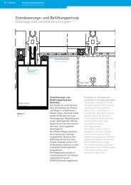
Entwässerungsprinzip<br />
Drainage principle<br />
Maßstab 1:1<br />
Scale 1:1<br />
Drainagenut<br />
Drainage channel<br />
Pfosten (3. Ebene)<br />
Mullion (level 3)<br />
EPDM-Dichtstück<br />
EPDM seal<br />
Entwässerungs- und<br />
Belüftungsprinzip des<br />
Glasfalzes<br />
Das System ist so konstruiert,<br />
dass die Glasfalze der Pfosten<br />
und Riegel in verschiedenen<br />
Ebenen liegen.<br />
Das eventuell auftretende<br />
Kondensat wird vom höher<br />
liegenden Riegelglasfalz in den<br />
tiefer liegenden Pfostenglasfalz<br />
und von dort kontrolliert nach<br />
unten abgeleitet (Drainagenut).<br />
Konstruktionsprinzipien<br />
Construction principles<br />
Riegel (1. Ebene)<br />
Transom (level 1)<br />
Principles of drainage and<br />
ventilation in the glazing rebate<br />
The system is designed so that<br />
the glass rebates of the mullions<br />
and transoms lie in different<br />
planes.<br />
Any condensation is drained from<br />
the higher transom glazing rebate<br />
into the lower mullion glazing<br />
rebate and then downwards<br />
under controlled conditions<br />
(drainage channel).<br />
Schüco | 39<br />
FW 60 + SG<br />
FW 50 + SG
40 | Schüco<br />
Konstruktionsprinzipien<br />
Construction principles<br />
Entwässerungsprinzip<br />
Drainage principle<br />
EPDM-Dichtstück<br />
EPDM seal<br />
Ausgleich der inneren<br />
Verglasungsebene<br />
Der Pfosten-Riegel-Anschluss im<br />
System ist so konstruiert, dass<br />
die ausgeklinkten Riegel auf der<br />
Dichtungsaufnahmenut der<br />
Pfosten befestigt werden. Der<br />
Höhenversatz wird durch unterschiedliche<br />
Dichtungshöhen<br />
ausgeglichen.<br />
Die Riegelprofile werden im<br />
Anschlussbereich zum Pfosten<br />
unterseitig mit einem<br />
EPDM-Dichtprofil abgedichtet.<br />
Equalising the inner glazing<br />
plane<br />
The mullion transom joint in the<br />
system is designed so that the<br />
notched transoms are secured to<br />
the gasket locating grooves.<br />
Different gasket thicknesses<br />
compensate for the differences in<br />
height.<br />
The transom profiles are sealed<br />
underneath with an EPDM gasket<br />
at the point at which they<br />
connect to the mullion.
Unterscheidungsmerkmale 1. bis 3. Ebene<br />
Characteristics, levels 1 to 3<br />
Darstellung ohne Deckschalen<br />
Shown without cover caps<br />
Systemerweiterung auf drei<br />
Entwässerungsebenen<br />
Zur Realisierung architektonischer<br />
Gestaltungswünsche ist<br />
eine zusätzliche Drainage-Ebene<br />
(Riegelprofile 2. Ebene) technisch<br />
sinnvoll.<br />
Sie stellt die kontrollierte Entwässerung<br />
z. B. von Auswechselungen<br />
bei großen Rasterbreiten<br />
(siehe Systemdarstellung) sicher.<br />
Durch drei höhenversetzte<br />
Entwässerungsebenen ist<br />
systemmäßig eine doppelte<br />
Sicherheit gewährleistet.<br />
Dichtungen<br />
Gaskets<br />
Extension of the system to<br />
three drainage levels<br />
For technical reasons, an<br />
additional level is necessary<br />
(transom profile, level 2) to fulfil<br />
architectural design<br />
requirements.<br />
This level controls the drainage,<br />
for example, at the transition for<br />
large module widths (see system<br />
illustration).<br />
The three drainage levels at<br />
different heights guarantee the<br />
system an even greater degree of<br />
reliability.<br />
H<br />
H<br />
H<br />
Konstruktionsprinzipien<br />
Construction principles<br />
Profilgeometrie<br />
Profile geometry<br />
H = gleiche Höhe<br />
H = same height<br />
Riegel (1. Ebene)<br />
Transom (level 1)<br />
Profilgrund<br />
Profile base<br />
Riegel (2. Ebene)<br />
Transom (level 2)<br />
Profilgrund<br />
Profile base<br />
Pfosten (3. Ebene)<br />
Mullion (level 3)<br />
gedrehte Darstellung<br />
Rotated<br />
= Ebenen<br />
Levels<br />
Schüco | 41<br />
FW 60 + SG<br />
FW 50 + SG
42 | Schüco<br />
Konstruktionsprinzipien<br />
Construction principles<br />
Verarbeitung und Verglasung<br />
Fabrication and glazing<br />
50<br />
20<br />
Maßstab 1:4<br />
Scale 1:4<br />
FW 50 + SG gezeichnet<br />
FW 60 + SG sinngemäß<br />
FW 50 + SG shown<br />
similar principles for FW 60 + SG<br />
50<br />
20<br />
50<br />
20<br />
50<br />
20<br />
32<br />
20<br />
50<br />
20
Verklebung der Structural Glazing-Isolierglasscheiben und der Structural<br />
Glazing-Paneele mit UV-beständigem Randverbund bzw. Verklebefuge mittels<br />
Zweikomponenten-Silikonkleber z. B. DOW CORNING® 993 oder Sikasil® SG-500<br />
auf eloxierten Aluminiumprofilen. Die Verarbeitungsvorschriften des<br />
Klebstofflieferanten DOW CORNING bzw. Sika Services AG sind unbedingt zu<br />
beachten. Die Oberflächenbeschaffenheit der Aluminiumprofile muss den<br />
Vorgaben von Schüco und des Klebstofflieferanten entsprechen.<br />
Die äußere Scheibe muss aus Einscheiben-Sicherheitsglas oder Verbundsicherheitsglas<br />
mit gehärteten Einzelscheiben bestehen.<br />
Die äußere Scheibe muss, mindestens zur Hälfte ihrer Dicke, durch den<br />
Glasträger gestützt werden.<br />
Beim Einsatz der Trockendichtung muss die Fuge (Nennmaß 20 mm) zwischen<br />
18 mm und 23 mm breit sein.<br />
Zum Ausfüllen der Wetterfuge eignen sich neben den Schüco Silikontrockendichtungen<br />
die Silikone DOW CORNING® 791, DOW CORNING® 756sms,<br />
DOW CORNING® 797 und DOW CORNING® 795 der Firma DOW CORNING<br />
sowie Sikasil® WS-305 und Sikasil® WS-605 S der Firma Sika Services AG.<br />
Scheibenüberstand aus optischen Gründen mit Silikon abspachteln, bedrucken<br />
etc.<br />
Weitere Hinweise<br />
Die mögliche Einbauhöhe von Structural Glazing-Fassaden unterliegt in der Regel<br />
nationalen und/oder lokalen Bestimmungen bzw. ist von weiteren Bedingungen, z. B.<br />
vom Einsatz einer zusätzlichen mechanischen Sicherung der Glasscheiben,<br />
abhängig.<br />
Es können nationale und/oder lokale Bestimmungen die Vorgaben und Anmerkungen<br />
der ETAG 002 bzw. ETA einschränken bzw. präzisieren. Nationale und lokale<br />
Bestimmungen sind ebenfalls zu berücksichtigen, falls die für die Baugenehmigung<br />
zuständige Stelle dies vorschreibt.<br />
In Ländern der Europäischen Union sind die Vorgaben der Europäischen Technischen<br />
Richtlinie (ETAG 002) für Structural Glazing-Fassaden und die in der Europäischen<br />
Technischen Zulassung (ETA) Nr. 05/0114 gemachten Angaben zwingend<br />
einzuhalten.<br />
Schüco empfiehlt diese auch dann einzuhalten, wenn das Bauvorhaben sich<br />
außerhalb der Europäischen Union befindet. Alle Abweichungen sind vorher Schüco<br />
anzuzeigen und von Schüco und/oder dem Klebstofflieferanten zu genehmigen.<br />
Glas und Klebstoff (Silikon)<br />
Es dürfen bei Isoliergläsern für eine so genannte Structural Glazing-Fassade nur<br />
Randverbundverklebungen verwendet werden, welche gegen UV-Strahlung<br />
widerstandsfähig sind. Die erforderliche Glasdicke und die Scheibenrandausbildung<br />
sind mit dem Glaslieferanten abzustimmen. Alle Kombinationen von Glas,<br />
Glasbeschichtung und Kleber sind unter den jeweiligen Herstellern abzustimmen<br />
(Gewährleistung). Die Verklebe-Eigenschaften zwischen der Oberflächenbeschichtung<br />
des Glases und dem Klebstoff (Silikon) sind vom Glashersteller nachzuweisen.<br />
Bei transparentem Glas ist eine Bemusterung vor Produktionsbeginn durchzuführen.<br />
Profile und Klebstoff (Silikon)<br />
Die mit dem Glas zu verklebenden Profile müssen die in der Europäischen<br />
Technischen Zulassung (ETA) beschriebenen Oberflächeneigenschaften aufweisen.<br />
Ersatzweise können durch objektbezogene Tests des Silikonlieferanten ausreichende<br />
Oberflächeneigenschaften auch bei Oberflächen nachgewiesen werden, die nicht<br />
nach ETA festgelegt sind. Für die rechtzeitige Vorlage aller erforderlichen<br />
Genehmigungen ist alleine der Verarbeiter der Profile verantwortlich.<br />
Konstruktionsprinzipien<br />
Construction principles<br />
Bonding of Structural Glazing double-glazed panes and of structural glazing<br />
panels with UV-resistant edge seals or bonded joints using two-component<br />
silicone adhesives e.g. Dow Corning® 993 or Sikasil® SG-500 on anodised<br />
aluminium profiles. The fabrication instructions from the adhesive<br />
manufacturers Dow Corning and Sika Services AG must be strictly adhered to.<br />
The surface properties of the aluminium profiles must correspond to Schüco<br />
specifications and those of the adhesive supplier.<br />
The outer pane must be toughened safety glass or laminated safety glass with<br />
individual panes of tempered glass.<br />
The outer pane must be supported over a minimum of half its thickness by the<br />
glazing support.<br />
When the dry gasket is used, the seal (nominal size 20 mm) must be between<br />
18 mm and 23 mm wide.<br />
Besides the Schüco silicone dry gasket, the weather gaps can be filled using<br />
silicones DOW CORNING® 791, DOW CORNING® 756sms, DOW CORNING® 797<br />
and DOW CORNING® 795 manufactured by Dow Corning and Sikasil® WS-305<br />
and Sikasil® WS-605 S manufactured by Sika Services AG.<br />
For reasons of appearance, apply silicone to the glass overlap and smooth it<br />
off.<br />
Further information<br />
The permissible installation height of structural glazing façades is generally subject<br />
to national and/or local regulations, or is dependent on other additional conditions<br />
such as the use of additional mechanical means of securing the glass.<br />
National and or local regulations may restrict the specifications and remarks of the<br />
ETAG 002 and ETA or make them more precise. National and local specifications<br />
must also be taken into account if prescribed by the body responsible for issuing<br />
building approvals.<br />
In the countries of the European Union the regulations of the European Technical<br />
Guidelines (ETAG 002) for structural glazing façades and the details given in the<br />
European Technical Approval (ETA) No. 05/0114 must be strictly adhered to.<br />
Schüco also recommends adherence to these even if the building project is located<br />
outside of the European Union. Any deviations from this must be declared to Schüco<br />
in advance, and approved by Schüco and/or the adhesive supplier.<br />
Glass and adhesive (silicone)<br />
All edge bonding used for insulating glass in a so-called structural glazing façade<br />
must be resistant to UV radiation. The required glass thickness and the pane edge<br />
specification must be agreed with the glazing supplier. All combinations of glass,<br />
glass coating and adhesive must be agreed with the relevant manufacturers<br />
(guarantee). The adhesive properties between the surface finish coating of the glass<br />
and the adhesive (silicone) must be tested by the glazing supplier. If transparent<br />
glass is used, a sample must be taken before production starts.<br />
Profiles and adhesive (silicone)<br />
The profiles, which are to be bonded to the glass, must show the surface finish<br />
properties described in the European Technical Approval (ETA). As an alternative,<br />
adequate surface properties on surfaces not laid down in the ETA can be proved by<br />
project-related tests carried out by the silicone supplier. The fabricator of the profiles<br />
is entirely responsible for presenting all the required approvals in good time.<br />
Schüco | 43<br />
FW 60 + SG<br />
FW 50 + SG
44 | Schüco<br />
alle 8 m bzw. nach 8 Feldern<br />
Every 8 m or every 8 fields<br />
80<br />
Konstruktionsprinzipien<br />
Construction principles<br />
Belüftungsprinzip<br />
Ventilation principle<br />
Gesamtbelüftung der Fassaden<br />
Bei dem Prinzip der Gesamtbelüftung<br />
erfolgt der Dampfdruckausgleich<br />
über Glasfalzbelüftungsstücke,<br />
welche in das<br />
Pfostenprofil im Bereich der Fuß-<br />
und Kopfpunkte der Fassade<br />
eingebracht werden.<br />
Bei Fassaden mit Höhen über 8 m<br />
bzw. mit mehr als 8 übereinander<br />
angeordneten Feldern werden<br />
alle weitere 8 m oder nach 8<br />
übereinander angeordneten<br />
Feldern zusätzliche Glasfalzbelüftungsstücke<br />
eingesetzt.<br />
Eventuell anfallendes Kondensat<br />
wird über die Pfosten nach unten<br />
hin kontrolliert aus der<br />
Konstruktion abgeleitet.<br />
40<br />
30<br />
Overall ventilation of façades<br />
When using overall ventilation,<br />
pressure is equalised using deflector<br />
blocks that are inserted into the<br />
mullion profile near the top and<br />
base points of the façade.<br />
For façades higher than 8 m or with<br />
more than 8 fields arranged one<br />
above the other, additional deflector<br />
blocks are inserted every 8 m or<br />
every 8 fields arranged one above<br />
the other.<br />
Condensation is drained<br />
downwards away from the<br />
construction via the mullions.<br />
Riegeldichtstück<br />
(Gesamtbelüftung)<br />
Transom seal<br />
(overall ventilation)<br />
Dampfdruckausgleich/<br />
Entwässerung<br />
Vapour pressure equalisation/<br />
drainage
Konstruktionsprinzipien<br />
Construction principles<br />
Maximale Glaslasten in Abhängigkeit vom Scheibenaufbau<br />
Maximum glass load is dependent on the glazing<br />
Hinweis:<br />
Statisch entsprechend dimensionierte<br />
Riegel und T-Verbinder<br />
werden vorausgesetzt.<br />
Note:<br />
Please ensure that the transoms<br />
and T-cleats are the correct size<br />
to meet the structural<br />
requirements.<br />
x<br />
32 – 36 6 6<br />
8<br />
400<br />
34 – 38 8 – 10<br />
10<br />
375<br />
36 – 40 6 – 8<br />
10<br />
350<br />
40 – 44 10 12<br />
350<br />
42 – 48 12 – 14<br />
14<br />
350<br />
32 – 36 6 6<br />
8<br />
450<br />
34 – 38 8 – 10<br />
10<br />
425<br />
36 – 40 6 – 8<br />
10<br />
400<br />
40 – 44 10 12<br />
400<br />
42 – 48 12 – 14<br />
14<br />
400<br />
6<br />
8<br />
10<br />
10<br />
12<br />
14<br />
6<br />
8<br />
10<br />
10<br />
12<br />
14<br />
6<br />
8<br />
10<br />
10<br />
12<br />
14<br />
6<br />
8<br />
10<br />
10<br />
12<br />
14<br />
6<br />
8<br />
10<br />
6<br />
8<br />
10<br />
10<br />
12<br />
14<br />
10<br />
12<br />
14<br />
6<br />
8<br />
10<br />
6<br />
8<br />
10<br />
10<br />
12<br />
14<br />
10<br />
12<br />
14<br />
300<br />
300<br />
300<br />
300<br />
350<br />
350<br />
350<br />
350<br />
kg<br />
kg<br />
Schüco | 45<br />
FW 60 + SG<br />
FW 50 + SG
46 | Schüco<br />
Konstruktionsprinzipien<br />
Construction principles<br />
Vordimensionierung Elementgrößen<br />
Dimensioning of unit sizes<br />
5.0<br />
4.5<br />
4.0<br />
3.5<br />
3.0<br />
2.5<br />
2.0<br />
1.5<br />
1.0<br />
0.5<br />
0.0<br />
5.0<br />
4.5<br />
4.0<br />
3.5<br />
3.0<br />
2.5<br />
2.0<br />
1.5<br />
1.0<br />
0.5<br />
0.0<br />
H (m)<br />
H (m)<br />
0.5<br />
Randbedingungen<br />
Parameters<br />
Benennung / Description Wert / Value<br />
Glasaufbau<br />
Glazing composition<br />
1.0 1.5 2.0 2.5 3.0 3.5 4.0 4.5 5.0<br />
B (m)<br />
siehe Diagramm<br />
see diagram<br />
Windsog / Negative wind load 1,000 kN/m 2<br />
Δ H 220 m<br />
Δ t 20 °C<br />
Δ Pmax 40 hPa<br />
∑ 13,2 kPa<br />
Verklebung / Bonding DC 993/Sikasil SG500<br />
6 20 6<br />
10 20 10<br />
0.5 1.0 1.5 2.0 2.5 3.0 3.5 4.0 4.5 5.0<br />
B (m)<br />
5.0<br />
4.5<br />
4.0<br />
3.5<br />
3.0<br />
2.5<br />
2.0<br />
1.5<br />
1.0<br />
0.5<br />
0.5<br />
0.0<br />
H (m)<br />
8 20 8<br />
0.0<br />
0.5 1.0 1.5 2.0 2.5 3.0 3.5 4.0 4.5 5.0<br />
B (m)<br />
H (m)<br />
5.0<br />
4.5<br />
4.0<br />
3.5<br />
3.0<br />
2.5<br />
2.0<br />
1.5<br />
1.0<br />
20 12<br />
12<br />
0.5 1.0 1.5 2.0 2.5 3.0 3.5 4.0 4.5 5.0<br />
B (m)<br />
Unzulässiger Bereich<br />
Inadmissible range
Vordimensionierung von Elementgrößen SG<br />
Mit der „Leitlinie für die europäische, technische Zulassung für geklebte<br />
Glaskonstruktionen“ (ETAG 002) wurde eine Grundlage geschaffen, die dazu beiträgt,<br />
das Risiko von Schäden und das Risiko von Gefahren während der Gesamtnutzungsdauer<br />
von geklebten Glaskonstruktionen zu minimieren.<br />
Im Sinne dieser Norm wurden zur Beurteilung einer ausreichenden Stabilität des<br />
Elementes gegenüber natürlichen Beanspruchungen nebenstehende Diagramme<br />
erstellt, die im Rahmen der Vordimensionierung unterstützend angewendet werden<br />
sollten.<br />
Für eine zielführende Nutzung dieser Diagramme müssen folgende Daten bekannt<br />
sein:<br />
Glasaufbau: Glasstärke innen / Scheibenzwischenraum / Glasstärke außen<br />
Windsog: Produkt aus dem von der Gebäudehöhe abhängigen Staudruck und<br />
dem aerodynamischen Beiwert für den Außendruck (cPe).<br />
B (m): Breite des Elements in Metern<br />
H (m): Höhe des Elementes in Metern<br />
Klimalast, bestehend aus:*<br />
ΔH: Differenz der Ortshöhe zwischen dem Einbauort und dem<br />
Herstellungsort,<br />
ΔT: Temperaturunterschiede zwischen Einbauort (Oberflächentemperatur<br />
Glas und Rahmen) und Produktion,<br />
ΔP met : Differenz des meteorologischen Luftdrucks am Einbauort und bei<br />
der Herstellung.<br />
∑: Materialkennwerte des entsprechenden Structural Glazing-Silikons<br />
(hier: Dehnungswert)<br />
Hinweis: Die Berechnung wurde auf Basis der unter „Randbedingungen“<br />
angegebenen Werte vorgenommen und gilt nur für diese Werte.<br />
Hinweise:<br />
Die europäisch technische Zulassung erlaubt eine maximale Elementgröße von 1,5 m<br />
× 2,5 m. Größere Elemente sind technisch möglich, für sie ist jedoch eine<br />
Zustimmung im Einzelfall erforderlich.<br />
Wird in der Praxis von den o. g. Randbedingungen für die Vordimensionierung<br />
abgewichen, ergeben sich andere zulässige Elementgrößen. Diese sind mit der<br />
Schüco International KG abzustimmen.<br />
Das oben dargestellte Diagramm dient ausschließlich zur Vordimensionierung. Vor<br />
der Ausführung ist objektbezogen eine exakte Dimensionierung erforderlich.<br />
Sprechen Sie die Schüco International KG an.<br />
Das oben dargestellte Vordimensionierungsdiagramm gibt auschließlich die<br />
technischen Einsatzgrenzen der Verklebung wieder. Zusätzlich sind die Einsatzgrenzen<br />
der Glasträger, T-Verbinder, Riegeldurchbiegung unter Eigenlast, Durchbiegung<br />
unter Winddruck/Windsog, Glasstatik usw. zu beachten.<br />
Konstruktionsprinzipien<br />
Construction principles<br />
Preliminary structural calculations of unit size SG<br />
The “Guidelines for European Technical Approval for Bonded Glass Constructions”<br />
(ETAG 002) are the legal basis for minimising the risk of damage and dangers during<br />
the use of bonded glass constructions.<br />
For this standard, the diagrams opposite have been created for ensuring sufficient<br />
stability of the unit with natural load requirements; the diagrams should be used to<br />
support preliminary structural calculations.<br />
For effective use of these diagrams you should be aware of the following data:<br />
Composition of glazing unit: Inner glass thickness / gap between the panes / outer<br />
glass thickness<br />
Negative wind load: Product for dynamic loading relating to building height and the<br />
aerodynamic coefficient for external pressure (cPe).<br />
W(m): Width of the unit in metres<br />
H (m): Height of the unit in metres<br />
Climate load, consisting of:*<br />
ΔH: Difference in height between the place of installation and the<br />
place of manufacture<br />
ΔT: Difference in temperature between the place of installation<br />
(surface temperature of glass and frame) and production<br />
ΔP met : Difference of meteorological air pressure at place of<br />
installation and manufacture.<br />
∑: Key values for materials for the relevant structural glazing<br />
silicone (here: expansion value)<br />
Note: The calculation will be carried out on the basis of the values given under<br />
the parameters and applies to those values only.<br />
Notes:<br />
The European Technical Approval regulations allow a maximum unit size of 1.5 m x<br />
2.5 m. Larger units are technically possible but approval is required for each<br />
individual project.<br />
In practice, the above dimensioning parameters will vary, giving rise to other<br />
additional unit sizes. These must be agreed with Schüco International KG.<br />
The diagram shown overleaf is intended exclusively for preliminary structural<br />
calculations. Precise calculations of the dimensions are needed for the specific<br />
project. Contact Schüco International KG.<br />
The preliminary calculation chart shown above gives the technical limits of use of<br />
the bonding. The limits of use of the glazing support, T-cleats, transom deflection<br />
under glass load, deflection under positive/negative wind load and glazing load<br />
calculations etc. must also be observed.<br />
* Wird nur bei der Berechnung des Isolierglasrandverbundes benötigt * Is only needed for calculation of insulating edge seals<br />
Schüco | 47<br />
FW 60 + SG<br />
FW 50 + SG
48 | Schüco<br />
Anwendungsbeispiele<br />
Examples<br />
Anwendungsbeispiele FW 50 + SG / FW 60 + SG<br />
FW 50 + SG / FW 60 + SG examples<br />
Die hier gezeigten Element-<br />
symbole geben eine Übersicht<br />
der möglichen Bauformen. Alle<br />
auf dieser Seite angegebenen<br />
Zahlen sind Seitenzahlen zu den<br />
im Folgenden gezeigten Anwendungsbeispielen.<br />
49<br />
50<br />
51<br />
52<br />
53<br />
65<br />
49<br />
50<br />
51<br />
65<br />
62<br />
61<br />
57<br />
58<br />
59<br />
63<br />
The diagrams shown here provide<br />
an overview of the different<br />
shapes that are possible. The<br />
numbers below are the page<br />
numbers for the relevant<br />
examples.<br />
64<br />
54<br />
55<br />
56<br />
60
U-förmige Trockenverglasung<br />
U-shaped dry glazing<br />
20<br />
Maßstab 1:1<br />
Scale 1:1<br />
6 20 8<br />
34 5 70<br />
FW 50 + SG gezeichnet<br />
FW 60 + SG sinngemäß<br />
FW 50 + SG shown<br />
similar principles for FW 60 + SG<br />
50<br />
20<br />
Anwendungsbeispiele<br />
Examples<br />
50<br />
6 20 8<br />
34 11 65<br />
Schüco | 49<br />
FW 60 + SG<br />
FW 50 + SG
50 | Schüco<br />
Anwendungsbeispiele<br />
Examples<br />
Flächenbündige Trockenverglasung<br />
Flush-fitted dry glazing<br />
32<br />
20<br />
Maßstab 1:1<br />
Scale 1:1<br />
FW 50 + SG gezeichnet<br />
FW 60 + SG sinngemäß<br />
FW 50 + SG shown<br />
similar principles for FW 60 + SG<br />
6 20 8<br />
34 5<br />
70<br />
50<br />
20<br />
32<br />
50<br />
20 8<br />
34 11<br />
6<br />
65
Nassversiegelung<br />
Wet sealing<br />
20<br />
Maßstab 1:1<br />
Scale 1:1<br />
6 20 8<br />
34 5 70<br />
FW 50 + SG gezeichnet<br />
FW 60 + SG sinngemäß<br />
FW 50 + SG shown<br />
similar principles for FW 60 + SG<br />
50<br />
20<br />
Anwendungsbeispiele<br />
Examples<br />
50<br />
6 20 8<br />
34 11 65<br />
Schüco | 51<br />
FW 60 + SG<br />
FW 50 + SG
52 | Schüco<br />
Anwendungsbeispiele<br />
Examples<br />
Vertikale Betonung<br />
Vertical emphasis<br />
32<br />
20<br />
Maßstab 1:1<br />
Scale 1:1<br />
FW 50 + SG gezeichnet<br />
FW 60 + SG sinngemäß<br />
FW 50 + SG shown<br />
similar principles for FW 60 + SG<br />
6 20 8<br />
34 5<br />
70<br />
50<br />
50<br />
65<br />
6 20 8<br />
34
Horizontale Betonung<br />
Horizontal emphasis<br />
Maßstab 1:1<br />
Scale 1:1<br />
FW 50 + SG gezeichnet<br />
FW 60 + SG sinngemäß<br />
FW 50 + SG shown<br />
similar principles for FW 60 + SG<br />
6 20<br />
34<br />
8<br />
70<br />
Flächenbündige Trockenverglasung<br />
Flush-fitted dry glazing<br />
50<br />
20<br />
32<br />
Anwendungsbeispiele<br />
Examples<br />
50<br />
20 8<br />
34 11<br />
6<br />
65<br />
Schüco | 53<br />
FW 60 + SG<br />
FW 50 + SG
54 | Schüco<br />
Anwendungsbeispiele<br />
Examples<br />
Segmentierung 0°– 5°<br />
Faceting 0°– 5°<br />
0°–5°<br />
Auch als Nassversiegelung ausführbar<br />
Also available as wet sealing<br />
Maßstab 1:1<br />
Scale 1:1<br />
FW 50 + SG gezeichnet<br />
FW 60 + SG sinngemäß<br />
FW 50 + SG shown<br />
similar principles for FW 60 + SG<br />
50<br />
20<br />
32<br />
0°–5°<br />
12<br />
20<br />
40<br />
8
Segmentierung 5°–10°<br />
Faceting 5°–10°<br />
Auch als Nassversiegelung ausführbar<br />
Also available as wet sealing<br />
Maßstab 1:1<br />
Scale 1:1<br />
FW 50 + SG gezeichnet<br />
FW 60 + SG sinngemäß<br />
FW 50 + SG shown<br />
similar principles for FW 60 + SG<br />
5°–10°<br />
50<br />
20<br />
32<br />
5°–10°<br />
Anwendungsbeispiele<br />
Examples<br />
40<br />
12 20<br />
8<br />
Schüco | 55<br />
FW 60 + SG<br />
FW 50 + SG
56 | Schüco<br />
Anwendungsbeispiele<br />
Examples<br />
Segmentierung 10°–15°<br />
Faceting 10°–15°<br />
Auch als Nassversiegelung ausführbar<br />
Also available as wet sealing<br />
Maßstab 1:1<br />
Scale 1:1<br />
FW 50 + SG gezeichnet<br />
FW 60 + SG sinngemäß<br />
FW 50 + SG shown<br />
similar principles for FW 60 + SG<br />
10°–15°<br />
50<br />
20<br />
32<br />
10°–15°<br />
36<br />
8 20<br />
8
Außenecke 90°<br />
90° outer corner<br />
32<br />
20<br />
Maßstab 1:2<br />
Scale 1:2<br />
FW 50 + SG gezeichnet<br />
FW 60 + SG sinngemäß<br />
FW 50 + SG shown<br />
similar principles for FW 60 + SG<br />
Anwendungsbeispiele<br />
Examples<br />
20<br />
32<br />
Schüco | 57<br />
FW 60 + SG<br />
FW 50 + SG
58 | Schüco<br />
Anwendungsbeispiele<br />
Examples<br />
Ganzglasecke<br />
All-glass corner<br />
32<br />
20<br />
Maßstab 1:2<br />
Scale 1:2<br />
FW 50 + SG gezeichnet<br />
FW 60 + SG sinngemäß<br />
FW 50 + SG shown<br />
similar principles for FW 60 + SG<br />
20<br />
32
Innenecke 90°<br />
90° inner corner<br />
Maßstab 1:2<br />
Scale 1:2<br />
FW 50 + SG gezeichnet<br />
FW 60 + SG sinngemäß<br />
FW 50 + SG shown<br />
similar principles for FW 60 + SG<br />
Anwendungsbeispiele<br />
Examples<br />
Schüco | 59<br />
FW 60 + SG<br />
FW 50 + SG
60 | Schüco<br />
Maßstab 1:2<br />
Scale 1:2<br />
Anwendungsbeispiele<br />
Examples<br />
Structural Glazing-Tür<br />
Structural glazing door<br />
Flügelüberdeckende Structural Glazing-Tür<br />
Leaf-enclosing structural glazing door
32<br />
20<br />
32<br />
Head of façade as fascia<br />
20 Kopfpunkt als Attika<br />
Anwendungsbeispiele<br />
Examples<br />
Maßstab 1:2<br />
Scale 1:2<br />
Schüco | 61<br />
FW 60 + SG<br />
FW 50 + SG
62 | Schüco<br />
32 32<br />
20<br />
20<br />
Anwendungsbeispiele<br />
Examples<br />
Deckenanschluss<br />
Top attachment<br />
Maßstab 1:2<br />
Scale 1:2<br />
FW 50 + SG gezeichnet<br />
FW 60 + SG sinngemäß<br />
FW 50 + SG shown<br />
similar principles for FW 60 + SG
Fußpunkt<br />
Sill<br />
Maßstab 1:2<br />
Scale 1:2<br />
32<br />
20<br />
FW 50 + SG gezeichnet<br />
FW 60 + SG sinngemäß<br />
FW 50 + SG shown<br />
similar principles for FW 60 + SG<br />
Anwendungsbeispiele<br />
Examples<br />
Schüco | 63<br />
FW 60 + SG<br />
FW 50 + SG
64 | Schüco<br />
Anwendungsbeispiele<br />
Examples<br />
Seitlicher Baukörperanschluss<br />
Side attachment to building structure<br />
6 20 8<br />
34<br />
Maßstab 1:2<br />
Scale 1:2<br />
FW 50 + SG gezeichnet<br />
FW 60 + SG sinngemäß<br />
FW 50 + SG shown<br />
similar principles for FW 60 + SG<br />
50<br />
20<br />
32
Maßstab 1:2<br />
Scale 1:2<br />
Übergangsbereich Vertikalfassade zum Pultdach<br />
Transition area of vertical façade for monopitch roof<br />
FW 50 + SG gezeichnet<br />
FW 60 + SG sinngemäß<br />
FW 50 + SG shown<br />
similar principles for FW 60 + SG<br />
50<br />
Anwendungsbeispiele<br />
Examples<br />
Schüco | 65<br />
FW 60 + SG<br />
FW 50 + SG
66 | Schüco<br />
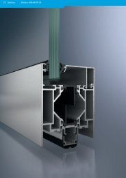
Profilübersicht FW 50 +<br />
Profile overview FW 50 +<br />
Pfosten FW 50 +<br />
FW 50 + mullions<br />
50<br />
322 250<br />
150<br />
322 300<br />
250<br />
336 240<br />
50<br />
50<br />
2<br />
50<br />
3<br />
65<br />
322 260<br />
175<br />
322 310<br />
50<br />
50<br />
2<br />
85<br />
322 270<br />
175<br />
326 250<br />
50<br />
50<br />
3<br />
E-Pfosten<br />
E-mullions<br />
85<br />
354 380<br />
50<br />
105<br />
105<br />
322 280<br />
200<br />
326 030<br />
50<br />
50<br />
50<br />
3<br />
125<br />
322 290<br />
225<br />
336 230<br />
125<br />
354 390 336 150<br />
336 200<br />
50<br />
50<br />
3<br />
50<br />
I x<br />
I y<br />
cm 4 cm 4<br />
322 250 31,37 19,31<br />
322 260 55,57 22,76<br />
322 270 108,46 28,14<br />
322 280 167,30 32,40<br />
322 290 278,66 38,43<br />
322 300 423,85 44,37<br />
322 310 663,00 52,81<br />
326 030 1010,31 76,76<br />
326 250 731,20 68,29<br />
336 150 184,82 35,72<br />
336 200 0,05 2,41<br />
336 230 1352,44 85,29<br />
336 240 1759,43 93,83<br />
354 380 64,71 26,08<br />
354 390 115,65 30,90<br />
50
Montagepfosten FW 50 +<br />
FW 50 + assembly mullions<br />
85<br />
50<br />
22 6 22<br />
85<br />
22 6 22<br />
323 940 323 950 323 960<br />
125<br />
323 980<br />
50<br />
22 6 22<br />
125<br />
323 990<br />
50<br />
50<br />
22 6 22<br />
105<br />
150<br />
326 010<br />
50<br />
22 6 22<br />
50<br />
22 6 22<br />
105<br />
323 970<br />
150<br />
326 020<br />
50<br />
22 6 22<br />
22 6 22<br />
Profilübersicht FW 50 +<br />
Profile overview FW 50 +<br />
Einschiebprofile für Stoßpunkte / statische Verstärkung<br />
Insert profiles for butt joints / structural reinforcement I x<br />
85<br />
50<br />
22 6 22<br />
105<br />
22 6 22<br />
323 270 323 280 323 290<br />
50<br />
125<br />
50<br />
22 6 22<br />
50<br />
I x<br />
I y<br />
cm 4 cm 4<br />
323 940 69,86 8,10<br />
323 950 42,37 6,61<br />
323 960 117,44 8,96<br />
323 970 76,63 7,38<br />
323 980 181,23 9,80<br />
323 990 124,08 8,15<br />
326 010 286,42 10,82<br />
326 020 204,50 9,11<br />
I y<br />
cm 4 cm 4<br />
323 270 2,45 0,27<br />
323 280 7,95 0,34<br />
323 290 18,25 0,41<br />
Maßstab 1:4<br />
Scale 1:4<br />
Schüco | 67<br />
FW 60 + SG<br />
FW 50 + SG
68 | Schüco<br />
Profilübersicht FW 50 +<br />
Profile overview FW 50 +<br />
Pfosten FW 50 +<br />
FW 50 + mullions<br />
Abwinkelbare Glasebene<br />
Variable angle glazing plane<br />
85<br />
323 040<br />
323 620<br />
200<br />
328 660<br />
45°<br />
50<br />
50<br />
3<br />
50<br />
27<br />
105<br />
323 050<br />
323 630<br />
55<br />
50<br />
28<br />
125<br />
323 060<br />
323 640<br />
Schrägdach-Bereich / Lichtdachkonstruktion<br />
Pitched roofs / skylight construction<br />
Firstriegel<br />
Ridge purlins<br />
322 490<br />
55<br />
55<br />
50<br />
Variabler Riegel<br />
Variable angle transoms<br />
322 640<br />
28<br />
28<br />
322 630<br />
150<br />
55<br />
50<br />
2.1<br />
55<br />
28<br />
175<br />
328 640 328 650<br />
50<br />
3<br />
I x<br />
I y<br />
cm 4 cm 4<br />
323 040 107,07 26,81<br />
323 620 107,07 26,81<br />
323 050 165,15 31,07<br />
323 630 165,15 31,07<br />
323 060 274,78 37,09<br />
323 640 274,78 37,09<br />
328 640 418,07 43,04<br />
328 650 687,36 64,40<br />
328 660 950,88 72,86<br />
I x<br />
cm4 cm4 322 490 25,57 14,64<br />
322 630 21,19 5,66<br />
322 640 19,07 5,03<br />
I y
Statikprofile FW 50 +<br />
FW 50 + structural profiles<br />
Einschiebprofile für Stoßpunkte / statische Verstärkung<br />
Insert profiles for butt joints / structural reinforcement<br />
85<br />
50<br />
105<br />
322 720 322 730 322 740<br />
175<br />
105<br />
50<br />
50<br />
200<br />
125<br />
50<br />
50<br />
326 270 326 050<br />
336 250 336 260<br />
201 216 201 217<br />
50<br />
125<br />
225<br />
152<br />
50<br />
50<br />
7<br />
322 780<br />
150<br />
322 750<br />
250<br />
50<br />
50<br />
175<br />
322 760<br />
50<br />
Profilübersicht FW 50 +<br />
Profile overview FW 50 +<br />
I x<br />
Schüco | 69<br />
I y<br />
cm 4 cm 4<br />
201 216 49,63 8,32<br />
201 217 81,45 9,38<br />
322 720 39,12 11,62<br />
322 730 74,61 14,27<br />
322 740 119,95 16,33<br />
322 750 226,51 19,12<br />
322 760 342,78 21,92<br />
326 050 403,26 16,60<br />
326 270 282,35 14,91<br />
336 250 560,25 18,31<br />
336 260 758,84 20,00<br />
351 980 194,17 39,71<br />
201 026 96,16 22,26<br />
Zur statischen Verstärkung können die Trägheitsmomente I x bzw.<br />
I y der Pfostenprofile und Einschieblinge addiert werden.<br />
Bei der statischen Berücksichtigung von Stahlprofilen (z. B.<br />
Einschiebprofile) wird das Trägheitsmoment (I x Wert in cm 4 ) im<br />
Verhältnis der E-Module (Stahl-Aluminium) mit 3 multipliziert.<br />
For structural reinforcement the structural values (moments of<br />
inertia) I x and I y of the mullion and insert profiles can be added<br />
together.<br />
When taking the structural integrity of steel profiles into account<br />
(e.g. insert profiles), the moment of inertia (I x value in cm 4 ) must<br />
be multiplied by 3 in relation to the E-modulus (steel-aluminium).<br />
Maßstab 1:4<br />
Scale 1:4<br />
FW 60 + SG<br />
FW 50 + SG
70 | Schüco<br />
Profilübersicht FW 50 +<br />
Profile overview FW 50 +<br />
Eckpfosten FW 50 +<br />
FW 50 + corner mullions<br />
65<br />
50<br />
65<br />
50<br />
85<br />
322 520 322 510 322 500<br />
84<br />
44<br />
85<br />
201 216 322 720 322 730<br />
Aluminiumaufsatzkonstruktion<br />
Aluminium add-on construction<br />
Pfosten<br />
Mullion<br />
50<br />
323 540<br />
22<br />
Riegel<br />
Transom<br />
50<br />
323 550<br />
50<br />
50<br />
22<br />
28<br />
85<br />
85<br />
50<br />
50<br />
105<br />
105<br />
50<br />
50<br />
65<br />
65<br />
50<br />
50<br />
Einsetzbar auf bauseitiger Holz- oder<br />
Stahlkonstruktion<br />
Can be used on timber or steel<br />
structures<br />
I x<br />
I y<br />
cm 4 cm 4<br />
322 500 68,71 202,58<br />
322 510 127,60 127,61<br />
322 520 54,25 54,25<br />
I x<br />
I y<br />
cm 4 cm 4<br />
201 216 49,63 8,32<br />
322 720 39,12 11,62<br />
322 730 74,61 14,27<br />
I x<br />
I y<br />
cm 4 cm 4<br />
323 540 4,26 10,81<br />
323 550 3,97 10,67
Riegel FW 50 +<br />
FW 50 + transoms<br />
Riegel, 1. Ebene<br />
Level 1 transoms<br />
6<br />
322 370<br />
21<br />
322 380<br />
27<br />
322 460<br />
323 840<br />
322 390<br />
322 400<br />
322 410<br />
322 420<br />
50<br />
45<br />
55<br />
50<br />
70<br />
50<br />
90<br />
50<br />
110<br />
50<br />
50<br />
50<br />
50<br />
322 430<br />
322 440<br />
322 450<br />
50<br />
90<br />
110<br />
130<br />
130<br />
155<br />
180<br />
E-Riegel, 1. Ebene<br />
Level 1 e-transoms<br />
336 200<br />
354 400<br />
354 410<br />
336 180<br />
50<br />
50<br />
50<br />
50<br />
50<br />
50<br />
Profilübersicht FW 50 +<br />
Profile overview FW 50 +<br />
351 980<br />
201 026<br />
100<br />
119.5<br />
I x<br />
40<br />
45<br />
I y<br />
cm 4 cm 4<br />
322 370 0,41 3,63<br />
322 380 3,02 8,93<br />
322 390 28,08 17,16<br />
322 400 49,42 20,77<br />
322 410 89,41 25,59<br />
322 420 144,16 30,41<br />
322 430 221,21 35,37<br />
322 440 354,71 41,98<br />
322 450 509,65 48,01<br />
322 460 5,15 10,37<br />
323 840 16,09 14,71<br />
336 180 175,43 34,54<br />
336 200 0,05 2,41<br />
354 400 64,43 24,90<br />
354 410 111,75 29,72<br />
351 980 194,17 39,71<br />
201 026 96,16 22,26<br />
Maßstab 1:4<br />
Scale 1:4<br />
Schüco | 71<br />
FW 60 + SG<br />
FW 50 + SG
72 | Schüco<br />
Profilübersicht FW 50 +<br />
Profile overview FW 50 +<br />
Montageriegel FW 50+<br />
50 50<br />
50<br />
50<br />
70<br />
50<br />
70<br />
50<br />
FW 50 + assembly transoms<br />
Riegel, 1. Ebene, unterer und oberer Fassadenanschluss<br />
Level 1 transoms for top and bottom façade attachment<br />
323 910<br />
323 920<br />
323 930<br />
90<br />
130<br />
130<br />
180<br />
Dehnriegel<br />
Expansion transom<br />
352 960<br />
32<br />
70<br />
I x<br />
I y<br />
cm 4 cm 4<br />
323 910 115,81 39,36<br />
323 920 292,14 43,56<br />
323 930 634,31 47,16<br />
I x<br />
I y<br />
cm 4 cm 4<br />
352 960 220,64 14,54
Riegel FW 50 +<br />
FW 50 + transoms<br />
Riegel, 2. Ebene<br />
Level 2 transoms<br />
322 330<br />
322 340<br />
322 350<br />
322 360<br />
84<br />
104<br />
124<br />
149<br />
50<br />
50<br />
50<br />
50<br />
Profilübersicht FW 50 +<br />
Profile overview FW 50 +<br />
I x<br />
cm4 cm4 322 330 84,60 23,98<br />
322 340 138,99 28,84<br />
322 350 214,83 33,76<br />
322 360 347,57 40,37<br />
I y<br />
Maßstab 1:4<br />
Scale 1:4<br />
Schüco | 73<br />
FW 60 + SG<br />
FW 50 + SG
74 | Schüco<br />
110 850<br />
50<br />
Profilübersicht FW 50 +<br />
Profile overview FW 50 +<br />
Deckschalen und Andruckprofile<br />
30<br />
25<br />
20<br />
15<br />
12<br />
140<br />
50 20 70<br />
100<br />
60<br />
45<br />
100<br />
40<br />
26<br />
17<br />
58<br />
15<br />
25<br />
25<br />
Cover cap profiles and pressure plates<br />
160 620<br />
112 720<br />
110 840<br />
110 860<br />
47<br />
112 710<br />
50<br />
50<br />
50<br />
50<br />
322 890<br />
322 900<br />
322 910<br />
Sonnenschutz / Raffstore<br />
Solar shading / external blind<br />
322 940<br />
50<br />
47 47 47<br />
50<br />
50<br />
50<br />
110 240<br />
110 250<br />
322 920<br />
122 980<br />
50<br />
50<br />
50<br />
50<br />
306 140<br />
322 190<br />
322 180<br />
322 930<br />
50<br />
50<br />
8<br />
50<br />
50
Edelstahl<br />
Stainless steel<br />
15<br />
202 285<br />
Sichtbar geschraubt<br />
With visible screw fixings<br />
6.5<br />
322 810<br />
8.5<br />
322 820<br />
8.5<br />
322 830<br />
50<br />
50<br />
50<br />
8.5<br />
322 840<br />
10<br />
322 850<br />
15<br />
322 860<br />
Flache Andruckprofile<br />
Flat pressure plates<br />
8<br />
328 770<br />
50.8<br />
47<br />
20<br />
202 286<br />
7<br />
328 780<br />
50.8<br />
50<br />
50<br />
50<br />
47<br />
24.6<br />
30<br />
47<br />
112 710<br />
322 870<br />
322 880<br />
50<br />
50<br />
Schrägdach<br />
Pitched roof<br />
Unsichtbar geschraubt<br />
With invisible screw fixings<br />
15<br />
47<br />
161 450<br />
323 310<br />
50<br />
12<br />
17.2<br />
Profilübersicht FW 50 +<br />
Profile overview FW 50 +<br />
161 460<br />
323 320<br />
50<br />
50<br />
323 390<br />
30<br />
Maßstab 1:4<br />
Scale 1:4<br />
Schüco | 75<br />
FW 60 + SG<br />
FW 50 + SG
76 | Schüco<br />
Profilübersicht FW 50 +<br />
Profile overview FW 50 +<br />
Deckschalen und Andruckprofile<br />
Cover cap profiles and pressure plates<br />
Deckschalen für Pfosten, unsichtbar verschraubt<br />
Invisible screw-fitted cover caps for mullions<br />
15<br />
323 330<br />
15<br />
323 340<br />
15°<br />
323 350<br />
20°<br />
323 360<br />
30°<br />
323 370<br />
35°<br />
323 380<br />
323 390<br />
30<br />
72<br />
80<br />
94.3<br />
106.4<br />
119.3<br />
136.5<br />
15<br />
15<br />
15<br />
15<br />
15<br />
323 190<br />
15<br />
323 200<br />
15<br />
323 210<br />
48.5<br />
53<br />
20<br />
10°<br />
30<br />
60 34<br />
25°<br />
34°
Innenecken, unsichtbar geschraubt<br />
Inner corners with invisible screw fixings<br />
46.7<br />
323 570<br />
49.3<br />
323 560<br />
8.5<br />
323 450<br />
8.5<br />
323 580<br />
50.5<br />
55<br />
60°<br />
45°<br />
Profilübersicht FW 50 +<br />
Profile overview FW 50 +<br />
Innenecken, sichtbar geschraubt<br />
Inner corners with visible screw fixings<br />
Maßstab 1:4<br />
Scale 1:4<br />
Schüco | 77<br />
FW 60 + SG<br />
FW 50 + SG
78 | Schüco<br />
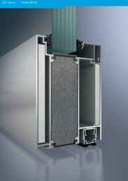
Profilübersicht FW 60 +<br />
Profile overview FW 60 +<br />
Pfosten FW 60 +<br />
FW 60 + mullions<br />
50<br />
324 010 324 020 324 030 324 040 324 050<br />
150<br />
60<br />
60<br />
65<br />
175<br />
324 060 324 070<br />
60<br />
60<br />
85<br />
200<br />
324 080<br />
60<br />
60<br />
105<br />
225<br />
324 090<br />
60<br />
60<br />
125<br />
250<br />
336 270<br />
60<br />
60<br />
I x<br />
I y<br />
cm 4 cm 4<br />
324 010 35,17 35,04<br />
324 020 63,25 42,32<br />
324 030 124,49 53,27<br />
324 040 195,32 62,41<br />
324 050 325,24 74,40<br />
324 060 500,62 86,83<br />
324 070 788,14 103,20<br />
324 080 1084,53 115,63<br />
324 090 1447,20 128,19<br />
336 270 1876,75 140,74
Montagepfosten FW 60 +<br />
FW 60 + assembly mullions<br />
85<br />
324 100<br />
324 110<br />
Profilübersicht FW 60 +<br />
Profile overview FW 60 +<br />
Einschiebprofile für Stoßpunkte / statische Verstärkung<br />
Insert profiles for butt joints / structural reinforcement I x<br />
85<br />
323 270<br />
60<br />
27 27<br />
22<br />
50<br />
6 22<br />
105<br />
324 120<br />
324 130<br />
105<br />
323 280<br />
60<br />
27 27<br />
22<br />
50<br />
6 22<br />
125<br />
324 140<br />
324 150<br />
125<br />
323 290<br />
60<br />
27 27<br />
22<br />
50<br />
6 22<br />
150<br />
324 160<br />
324 170<br />
60<br />
27 27<br />
I x<br />
I y<br />
cm 4 cm 4<br />
324 100 79,01 13,73<br />
324 110 49,50 12,13<br />
324 120 134,40 15,22<br />
324 130 90,88 13,47<br />
324 140 209,72 16,65<br />
324 150 149,15 14,78<br />
324 160 335,73 18,39<br />
324 170 249,53 16,40<br />
I y<br />
cm 4 cm 4<br />
323 270 2,45 0,27<br />
323 280 7,95 0,34<br />
323 290 18,25 0,41<br />
Maßstab 1:4<br />
Scale 1:4<br />
Schüco | 79<br />
FW 60 + SG<br />
FW 50 + SG
80 | Schüco<br />
Profilübersicht FW 60 +<br />
Profile overview FW 60 +<br />
Pfosten FW 60 +<br />
FW 60 + mullions<br />
Variable Pfosten<br />
Variable mullion I x<br />
85<br />
324 180<br />
200<br />
327 010<br />
60<br />
60<br />
105<br />
324 190<br />
225<br />
327 020<br />
60<br />
60<br />
250<br />
125<br />
324 200<br />
336 290<br />
60<br />
60<br />
150<br />
324 210<br />
60<br />
175<br />
324 990<br />
60<br />
I y<br />
cm 4 cm 4<br />
324 180 122,87 51,43<br />
324 190 192,82 60,57<br />
324 200 320,86 72,55<br />
324 210 494,10 84,99<br />
324 990 741,73 97,30<br />
327 010 1022,05 109,73<br />
327 020 1365,72 122,28<br />
336 290 1773,68 134,84
Statikprofile FW 60 +<br />
FW 60 + structural profiles<br />
Profilübersicht FW 60 +<br />
Profile overview FW 60 +<br />
Einschiebprofile für Stoßpunkte / statische Verstärkung<br />
Insert profiles for butt joints / structural reinforcement I x<br />
85<br />
324 300<br />
200<br />
324 350<br />
60<br />
60<br />
105<br />
324 310<br />
225<br />
324 360<br />
60<br />
60<br />
125<br />
324 320<br />
250<br />
336 280<br />
60<br />
60<br />
150<br />
324 330<br />
152<br />
60<br />
11<br />
324 960<br />
175<br />
324 340<br />
60<br />
Schüco | 81<br />
I y<br />
cm 4 cm 4<br />
324 300 41,42 13,91<br />
324 310 78,48 16,53<br />
324 320 125,84 18,58<br />
324 330 236,91 21,37<br />
324 340 357,78 24,18<br />
324 350 519,96 26,97<br />
324 360 741,70 30,26<br />
336 280 1002,65 33,02<br />
Maßstab 1:4<br />
Scale 1:4<br />
FW 60 + SG<br />
FW 50 + SG
82 | Schüco<br />
Profilübersicht FW 60 +<br />
Profile overview FW 60 +<br />
Eckpfosten FW 60 +<br />
FW 60 + corner mullions<br />
85<br />
324 220<br />
64.2<br />
324 300<br />
Aluminiumaufsatzkonstruktion<br />
Aluminium add-on construction<br />
Pfosten<br />
Mullion<br />
324 680<br />
53<br />
60<br />
60<br />
85<br />
22<br />
60<br />
Riegel<br />
Transom<br />
60<br />
324 690<br />
28<br />
28<br />
I x<br />
I x<br />
I y<br />
cm 4 cm 4<br />
324 300 41,42 13,91<br />
I x<br />
I y<br />
cm 4 cm 4<br />
324 680 5,07 19,78<br />
324 690 5,42 20,95<br />
I y<br />
cm 4 cm 4<br />
324 220 138,44 138,44
Riegel FW 60 +<br />
FW 60 + transoms<br />
Profilübersicht FW 60 +<br />
Profile overview FW 60 +<br />
Riegel, 1. Ebene<br />
Level 1 transoms I x<br />
6<br />
324 400<br />
21<br />
324 410<br />
60<br />
27<br />
324 420<br />
324 440<br />
324 450<br />
324 460<br />
324 470<br />
324 480<br />
55<br />
60<br />
70<br />
60<br />
90<br />
110<br />
60<br />
130<br />
60<br />
60<br />
60<br />
60<br />
324 490<br />
324 500<br />
326 940<br />
100<br />
130<br />
155<br />
180<br />
205<br />
Einschiebprofile für große<br />
Glaslasten<br />
Insert profiles for heavy glass<br />
loads<br />
336 090<br />
201 026<br />
40<br />
60<br />
60<br />
60<br />
60<br />
I y<br />
cm 4 cm 4<br />
324 400 0,44 6,11<br />
324 410 3,42 16,38<br />
324 420 5,94 19,39<br />
324 440 32,92 33,49<br />
324 450 58,61 41,02<br />
324 460 107,49 51,07<br />
324 470 175,35 61,11<br />
324 480 270,93 71,30<br />
324 490 419,34 83,86<br />
324 500 610,49 96,42<br />
326 940 849,28 108,98<br />
I x<br />
I y<br />
cm 4 cm 4<br />
336 090 208,21 58,55<br />
201 026 96,16 22,26<br />
Maßstab 1:4<br />
Scale 1:4<br />
Schüco | 83<br />
FW 60 + SG<br />
FW 50 + SG
84 | Schüco<br />
Profilübersicht FW 60 +<br />
Profile overview FW 60 +<br />
Riegel, 2. Ebene<br />
Level 2 transoms I x<br />
324 510<br />
324 520<br />
324 530<br />
324 540<br />
84<br />
104<br />
124<br />
149<br />
60<br />
60<br />
60<br />
60<br />
I y<br />
cm 4 cm 4<br />
324 510 100,14 47,78<br />
324 520 166,00 57,82<br />
324 530 259,33 68,01<br />
324 540 405,10 80,57
Profilübersicht FW 60 +<br />
Profile overview FW 60 +<br />
Lichtdachaufsatzkonstruktion<br />
Skylight add-on constructions I x<br />
Pfosten<br />
Mullion<br />
7<br />
328 980<br />
Schrägdach<br />
Pitched roof<br />
Firstriegel<br />
Ridge purlins<br />
45°<br />
324 370<br />
60<br />
60<br />
33.3<br />
22<br />
55<br />
Riegel<br />
Transom<br />
6<br />
39.3<br />
328 990<br />
60<br />
328 700<br />
60<br />
37.5<br />
70<br />
Variabler Riegel<br />
Variable angle transoms<br />
55<br />
37<br />
324 560 324 550<br />
55<br />
37<br />
55<br />
55<br />
37<br />
37<br />
I x<br />
Schüco | 85<br />
I y<br />
cm 4 cm 4<br />
324 370 33,99 25,81<br />
324 550 22,89 8,76<br />
324 560 24,72 10,17<br />
328 700 60,04 33,78<br />
I y<br />
cm 4 cm 4<br />
328 980 5,70 7,02<br />
328 990 6,30 6,28<br />
Maßstab 1:4<br />
Scale 1:4<br />
FW 60 + SG<br />
FW 50 + SG
86 | Schüco<br />
Profilübersicht FW 60 +<br />
Profile overview FW 60 +<br />
Deckschalen und Andruckprofile<br />
Cover cap profiles and pressure plates<br />
Standard-Fassade<br />
Standard façade<br />
162 880<br />
12<br />
160 630<br />
15<br />
162 180<br />
25<br />
110 910<br />
20<br />
110 920<br />
30<br />
182 910<br />
60<br />
60<br />
60<br />
60<br />
56<br />
60<br />
Edelstahl<br />
Stainless steel<br />
15<br />
202 287<br />
61<br />
45<br />
110 930<br />
60<br />
110 940<br />
100<br />
110 950<br />
55<br />
324 880<br />
20<br />
202 288<br />
56 56 56<br />
60<br />
60<br />
60<br />
60<br />
61<br />
21<br />
110 260<br />
162 880<br />
34<br />
110 270<br />
100<br />
324 890<br />
60<br />
60<br />
60<br />
25<br />
324 870<br />
40<br />
322 170<br />
25<br />
324 870<br />
60<br />
60<br />
60<br />
Flache Deckschalen<br />
Flat cover caps<br />
6<br />
354 450<br />
57.4<br />
6<br />
354 460<br />
57.4
Schrägdach<br />
Pitched roof<br />
12<br />
162 170<br />
60<br />
10<br />
162 160<br />
Sichtbar geschraubt<br />
With visible screw fixings<br />
6.5<br />
60<br />
324 810 324 830<br />
8.5<br />
324 900<br />
Unsichtbar geschraubt<br />
With invisible screw fixings<br />
15<br />
323 330<br />
15<br />
323 340<br />
15°<br />
323 350<br />
20°<br />
323 360<br />
30°<br />
323 370<br />
35°<br />
323 380<br />
60<br />
72<br />
80<br />
94.3<br />
106.4<br />
119.3<br />
136.5<br />
15<br />
8.5<br />
8.5<br />
324 840<br />
15<br />
15<br />
15<br />
57<br />
60<br />
60<br />
8.5<br />
324 850<br />
30<br />
324 860<br />
15<br />
324 700<br />
15<br />
324 710<br />
15<br />
324 720<br />
323 390<br />
30<br />
60<br />
60<br />
58.5<br />
63<br />
70<br />
20<br />
30<br />
34<br />
10°<br />
25°<br />
34°<br />
Profilübersicht FW 60 +<br />
Profile overview FW 60 +<br />
Schüco | 87<br />
Maßstab 1:4<br />
Scale 1:4<br />
FW 60 + SG<br />
FW 50 + SG
88 | Schüco<br />
Profilübersicht FW 60 +<br />
Profile overview FW 60 +<br />
Deckschalen und Andruckprofile<br />
Cover cap profiles and pressure plates<br />
Sichtbar geschraubt<br />
With visible screw fixings<br />
8.5<br />
324 770<br />
8.5<br />
324 780<br />
8.5<br />
324 790<br />
8.5<br />
324 800<br />
8.5<br />
327 470<br />
8.5<br />
327 480<br />
6.5<br />
327 460<br />
8.5<br />
324 750<br />
68<br />
77<br />
86<br />
93<br />
100<br />
113<br />
118<br />
20<br />
122<br />
7.5°<br />
15°<br />
22.5°<br />
30°<br />
30°<br />
37.5°<br />
30°<br />
45°<br />
8.5<br />
327 490<br />
8.5<br />
324 760<br />
8.5<br />
324 730<br />
8.5<br />
324 740<br />
60<br />
60<br />
60<br />
90<br />
30<br />
40<br />
Deckschalen für Riegel<br />
Cover caps for transom<br />
6.5<br />
324 820<br />
7<br />
327 450<br />
60<br />
90
Deckschalen und Andruckprofil für Innenecken<br />
Cover caps and pressure plate for inner corners<br />
324 910<br />
15<br />
324 920<br />
8.5<br />
324 930<br />
8.5<br />
324 940<br />
65<br />
60°<br />
45°<br />
Profilübersicht FW 60 +<br />
Profile overview FW 60 +<br />
Maßstab 1:4<br />
Scale 1:4<br />
Schüco | 89<br />
FW 60 + SG<br />
FW 50 + SG