Einbauanleitung
Einbauanleitung
Einbauanleitung

Sie wollen auch ein ePaper? Erhöhen Sie die Reichweite Ihrer Titel.
YUMPU macht aus Druck-PDFs automatisch weboptimierte ePaper, die Google liebt.
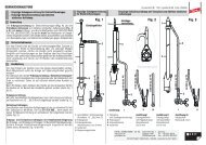
3. Connecting/installing the air-termination rods<br />
The air-termination rod support features different installation options (see Fig. 6).<br />
Metal air-termination rods with a maximum length of 1.5 m (16/10 mm) and GRP/Al air-termination<br />
rods can be used for a wind speed up to 145 Km/h (wind load zone II) (see Fig. 6).<br />
Air-termination tips, Ø 10 mm, L=1000 mm<br />
(material: aluminium, copper, stainless steel)<br />
Fig.<br />
Fig. 1<br />
6<br />
Air-termination rods, Ø 16/10 mm, max. L=1500 mm<br />
(material: aluminium, copper, stainless steel<br />
(also tubular air-termination rods))<br />
GRP/AI air-termination rods, Ø 16 /10 mm, modular system with air-termination tip<br />
Ø 10 mm, L= 1000 mm and GRP rod Ø 16 mm, L = 415 mm, Part No. 106 214<br />
Note:<br />
The distance from the next fixing point of the air-termination conductor must be ≤ 3,4 m!<br />
GRP/AI air-termination rods, Ø 16 /10 mm, max. L= 1660 mm, Part No. 106 207<br />
(pressed)<br />
Note:<br />
The distance from the next fixing point of the air-termination conductor must be ≤ 1,1 m!<br />
Fig. 2 Fig. 3 Fig. 4<br />
7<br />
or GRP rod Ø 16 mm, L = 675 mm, Part No. 106 217<br />
Note:<br />
The distance from the next fixing point of the air-termination conductor must be ≤ 1,1 m!