Einbauanleitung
Einbauanleitung
Einbauanleitung

Erfolgreiche ePaper selbst erstellen
Machen Sie aus Ihren PDF Publikationen ein blätterbares Flipbook mit unserer einzigartigen Google optimierten e-Paper Software.
1. Use / design<br />
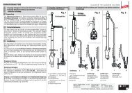
The air-termination rod support can be fitted with an air-termination rod/air-termination tip or a GRP/Al<br />
air-termination rod with a diameter of 16/10 mm. The system is used for isolated air-termination<br />
systems of transmitters/receivers (parabolic, terrestrial antennas) or e.g. for photovoltaic or solar thermal<br />
systems on pitched roofs. The air-termination rod support is delivered in an unassembled condition<br />
(see Fig. 1).<br />
two wood screws<br />
(torx T40, 8 x120/80)<br />
two spring washers<br />
two cleats<br />
2<br />
bushing<br />
D= 16/16/10 mm<br />
brace D=16 mm<br />
Fig. 1<br />
Air-termination rod support in its unassembled condition<br />
2. Installation of the air-termination rod support<br />
M10 x 16 mm<br />
M10 x 16 mm<br />
M10 x 16 mm<br />
The air-termination rod support may only be installed on a suitable and stable substructure.<br />
Counter battens are required for installation.<br />
The air-termination rod support is designed for a torque up to 35 Nm which accordingly acts on the substructure.<br />
It must not be used for plain tiles.<br />
The following tools are required to install an air-termination rod support:<br />
- Cordless screwdriver<br />
- Wood drill (diameter of 5 mm)<br />
- Bit insert, torx T40<br />
- Open-end/ring spanner, wrench size 17<br />
- Water level<br />
- Folding rule