elektro-pneumatikventile Typenreihe -4-EPVA/-4-EPVO - fh-teknik a/s
elektro-pneumatikventile Typenreihe -4-EPVA/-4-EPVO - fh-teknik a/s
elektro-pneumatikventile Typenreihe -4-EPVA/-4-EPVO - fh-teknik a/s

Sie wollen auch ein ePaper? Erhöhen Sie die Reichweite Ihrer Titel.
YUMPU macht aus Druck-PDFs automatisch weboptimierte ePaper, die Google liebt.
<strong>elektro</strong>-<strong>pneumatikventile</strong> <strong>Typenreihe</strong> -4-<strong>EPVA</strong>/-4-<strong>EPVO</strong><br />
electro-pneumatic-valves Series -4-<strong>EPVA</strong>/-4-<strong>EPVO</strong><br />
seite page 1<br />
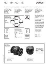
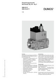
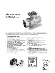
<strong>elektro</strong>-<strong>pneumatikventile</strong><br />
Mit EG-Baumusterprüfbescheinigung nach<br />
DIN-EN 161/DIN 3394-1, gemäß<br />
derGasgeräterichtlinie (90/396/EWG)<br />
Baureihe ... -4-<strong>EPVA</strong> ...<br />
Druckbereich bis 10 bar<br />
Nennweite: DN 15 – DN 400<br />
Umgebungstemperatur –20° - +60°C<br />
auch lieferbar in<br />
Anwendung<br />
Als automatische Absperrventile, welche die Gaszufuhr an Gasbrennern<br />
und Gasgeräten, und den Gasdurchfluss in Rohrleitungen absperren und<br />
freigeben.<br />
Hauptmerkmale kmale<br />
Die automatischen Absperrventile Klasse A, Gruppe 2 nach DIN-EN 161/<br />
DIN 3394-1, gemäß derGasgeräterichtlinie (90/396/EWG)<br />
- Funktion: Stromlos geschlossen / Stromlos offen<br />
- lieferbar mit Flanschanschluß nach ISO 7005,<br />
bzw. DIN 2501 Teil 1 bzw. Teil 2.<br />
- Antrieb durch einseitig beaufschlagten Kolben mit Rückstellfeder.<br />
- Betätigung durch Steuerventil in 3 / 2 - Wegeausführung der<br />
<strong>Typenreihe</strong> 10 - EVD …<br />
- Steuermedium Druckluft min. 4 bar, max. 10 bar.<br />
- Die autom. Absperrventile sind stopfbuchslos und arbeiten geräuscharm.<br />
- Sie geben beim Öffnen den Gasdurchfluß unverzögert oder zeitverzögert<br />
(Option) frei. Beim Schließen wird der Gasdurchfluß innerhalb einer<br />
Sekunde dicht abgesperrt.<br />
- DerAntrieb ist vom gasführenden Gehäuse durch ein Zwischenstück<br />
abgesetzt.<br />
- Die Abdichtung an derVentilspindel erfolgt durch spezielle<br />
Lippenringe, wodurch eine absolute Dichtheit gewährleistet ist.<br />
- Durch den Einsatz von Freistrom-Ventilgehäusen entstehen geringe<br />
Druckverluste.<br />
- Unbedingte Dichtheit durch speziell entwickelte Ventilteller.<br />
Druckbereich der <strong>Typenreihe</strong><br />
pressure range of the type series<br />
130.000.002-00<br />
1-4-<strong>EPVA</strong>...-4 … = 0-1 bar<br />
2-4-<strong>EPVA</strong>...-4 … = 0-2 bar<br />
3-4-<strong>EPVA</strong>...-4 … = 0-3 bar<br />
4-4-<strong>EPVA</strong>...-4 … = 0-4 bar<br />
6-4-<strong>EPVA</strong>...-4 … = 0-6 bar<br />
holtumsweg 13<br />
d-47652 weeze<br />
electro-pneumatic-valves<br />
EC Type Test Certificate, tested to<br />
DIN-EN 161 3394-1, in accordance with the<br />
EC Gas Apperatus Guideline (90/396/EEC)<br />
type: ... -4-<strong>EPVA</strong>...<br />
pressurs range up to 10 bar<br />
nominal size DN 15 up to DN 400<br />
ambient temperature range -20° - +60°C<br />
also deliverable in<br />
Application<br />
As automatic shut-off valves, which open and close the gas flow to<br />
gas burners and gas aquipment and also open and close the flowrate<br />
in pipe network.<br />
Main ain char characteristics<br />
All safety shut- off valves are according to the DIN- EN 161/DIN<br />
3394-1, in accordance with the EG-Gas Apparatus Guideline (90/396/EWG)<br />
for automatic shut-off valves Class A, Group 2.<br />
Function: currentless close/currentless open<br />
- Deliverable with flang fitting to ISO 7005 or DIN 2501 Part 1<br />
- Drive with single-side pressurised piston with return spring.<br />
- Actuation by means of controll valve in 3/2- way design,<br />
Range of types: 10- EVD ...<br />
- Controll medium is compressed air, pressure 4 - 10 bar.<br />
- The automatic shut-off valves are glandless and function silently.<br />
- On opening procedure with the opening permit they give the crosssection<br />
without delay or with a delay (option). On closing procedure<br />
the cross-section is reliable shut-off tight without delay<br />
(within a second).<br />
- The drive is seperated from the medium-bearing houseing by a spacer.<br />
- The valve spindle is sealed by special lip seals, thus ensuring absolute<br />
leak tightness.<br />
- Lowpressure loss through non-choked valve housing.<br />
- Absolutely leak-tightness thanks to specially developed valve disc.<br />
10-4-<strong>EPVO</strong>... -4R … = 0-10 bar<br />
10-4-<strong>EPVO</strong>... H-4R … = 0-10 bar<br />
fon: +49-28 37-91 34-0<br />
fax: +49-2837-1444<br />
Zertifiziert nach DIN EN ISO 9001<br />
Certified to DIN EN ISO 9001<br />
www.uni-geraete.de<br />
info@uni-geraete.de
- Hohe Schalthäufigkeit (1500/h) und lange Lebensdauer.<br />
- Durch geeignete Federn wird die Schließkraft erzeugt,<br />
die ein sicheres Schließen des automatischen Absperrventils<br />
bei Ausfall oderUnterbrechung dervon außen<br />
zugeführten Stellantriebs-Energie gewährleistet.<br />
- Die Abdichtung erfolgt durch weiche, elastische<br />
Dichtungswerkstoffe, geprüft nach DIN 3535 für Gase<br />
derersten, zweiten und dritten Gasfamilie, auf Ventilsitz<br />
aus Edelstahl.<br />
- Die automatischen Absperrventile sind direkt gesteuert.<br />
Alle Innenteile, die nicht aus NE-Metallen bzw. Edelstahl<br />
bestehen, sind mit einem speziellen Korrosionsschutz<br />
behandelt.<br />
Wie in DIN-EN 161 Abschnitt 2.6 und DIN 3394 Teil 1,<br />
Abschnitt 3,5 aufgeführt, muß vor jedes automatische<br />
Abspe rventil ein speziellerSchmutzfängerangebracht<br />
werden. Bei zwei zu einer Gruppe montierten automatischen<br />
Absperrventilen genügt ein, vor das erste Ventil angebrachterSchmutzfänger.<br />
Die Schmutzfängersind auch<br />
separat lieferbar.<br />
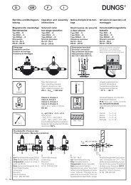
Funktionsbeschreibung<br />
Öffnungsvorgang:<br />
Bei Beaufschlagung des Antriebskolbens hebt dieser,<br />
gegen den auf dem Ventiltellerlastenden Druck des<br />
Mediums und die Federkraft an. Dadurch wird der<br />
Querschnitt entsprechend der Nennweite des Automatischen<br />
Absperrventils innerhalb von 0,3-2 Sekunden völlig<br />
frei. DieserZustand bleibt fürdie DauerderBeaufschlagung<br />
bestehen.<br />
Schließvorgang:<br />
Nach Umschalten des Steuerventils (3/2-Wegeventil)<br />
wird derVentilteller(mit weichelastischerDichtung,<br />
überdie Ventilspindel mit dem Antriebskolben verbunden)<br />
durch die auf dem Antriebskolben befindlichen,<br />
vorgespannten Druckfedern, entsprechend der Nennweite<br />
des automatischen Absperrventils in weniger als<br />
1 Sekunde auf den Ventilsitz gepreßt und sperrt den<br />
Gasdurchfluß dann dicht ab.<br />
holtumsweg 13<br />
d-47652 weeze<br />
fon: +49-28 37-91 34-0<br />
fax: +49-2837-1444<br />
www.uni-geraete.de<br />
info@uni-geraete.de<br />
- High switching frequency (1500 cycles/hour), long service.<br />
- Appropriate springs are used to generate the closing force<br />
which guarantees a reliable closing of the automatic shutoff<br />
valve in the event of failure of or interruption in the<br />
externally supplied valve actuating energy.<br />
- Sealing is effected with soft elastic sealing materials tested<br />
to DIN 3535 on valve seat of non-rusting special steel.<br />
- The automatic shut-off valves are directly controlled.<br />
All internal parts which are not made of non-ferrous metals<br />
or stainless steel are trade with a special rust-proof coating.<br />
As specified in DIN EN 161 Section 2.6 and DIN 3394 Part<br />
1 Section 3.5, a special dirt trap must be installed unstream<br />
of all automatic shut-off valves. Where two automatic shut-off<br />
valves are combined to form a group, one dirt trap installed<br />
of the first valve is sufficient. The dirt traps are also available<br />
separately.<br />
Description ion of Func Functions<br />
Opening procedure:<br />
When the drive piston is pressurised, it opens against the<br />
pressure of the medium acting on the valve disc and the<br />
spring pressure, thereby opening the full cross-section<br />
corresponding to the nominal width of the automatic shutoff<br />
valve within 0,3 – 2 seconds. This condition is maintained<br />
as long as the piston is pressurised.<br />
Closing procedure:<br />
When the control valve (2/3- way directional control valve)<br />
swiches over, the valve disc (with soft elastic seal and linked<br />
to the drive piston via the valve spindle) is pressed against<br />
the valve seat by the preioaded pressure springs on the<br />
drive piston corresponding to the nominal width of the<br />
automatic shut-off valve within less than 1 second, thereby<br />
shutting of the gas flow.<br />
seite page 2
Montage-Richtlinien<br />
DerEinbau des automatischen Abspe rventils muß in der,<br />
durch einen am Ventilgehäuse befindlichen Pfeil, angegebenen<br />
Durchflußrichtung erfolgen.<br />
DerEinbau in die Rohrleitung kann Lagen unabhängig erfolgen.<br />
Es ist darauf zu achten, daß das Steuerventil mit senkrecht<br />
stehendem Antrieb montiert wird.<br />
Nach Einbau des Automatischen Absperrventils sollte die<br />
Rohrleitung vor Inbetriebnahme bei geöffnetem Absperrventil<br />
gründlich gespült werden, da die Kunststoffdichtungen empfindlich<br />
gegen Fremdkörper sind.<br />
Ist im bzw. am Eingang des Ventils kein Schmutzfänger<br />
angebracht, so ist dafür Sorge zu tragen, daß ein geeigneter<br />
Schmutzfängerin nicht zu großerEntfernung vordem Eingang<br />
des Ventils installiert wird. Die lichten Weiten der Öffnung<br />
des Siebes dürfen nicht größer sein als 1,5 mm und sie dürfen<br />
einen 1 mm Prüfdorn nicht durchlassen. Der Schmutzfänger<br />
soll das Eindringen von Fremdkörpern verhindern.<br />
Die Funktions- bzw. sicherheitstechnische Anforderung an die<br />
Dichtheit nach DIN-EN 161 Abschnitt 3.7 (September1991) und<br />
nach DIN 3394 Teil 1 Abschnitt 3,7 (November1982) werden<br />
erfüllt.<br />
Bestellzusätze<br />
Bestellzusätze entnehmen Sie bitte unserem Typenschlüssel.<br />
Warnhinweis<br />
Bei den 3/2 – Wege-Steuerventilen ist darauf zu achten, daß<br />
derQuerschnitt (lichte Weite) derEntlüftungsleitung durch<br />
Verunreinigung oder durch Knicken nicht verengt wird.<br />
Fernerist darauf zu achten, daß derEntlüftungsein- und<br />
ausgang verschmutzungssicher ausgeführt wird.<br />
seite page 3 holtumsweg 13<br />
d-47652 weeze<br />
Installat allation ion Instr Instructions<br />
The automatic shut-off valve must be installed in the flow<br />
direction indicated by the arrow on the valve housing.<br />
The installation position in the line can be freely selected. Ensure<br />
that the controll valve is installed with upright drive.<br />
After installation of the automatic shut-off valve, the line should<br />
be thouroughly flushed before commissioning with the automatic<br />
shut-off valve open as the plastic seal is highly sensitive for<br />
foreign bodies.<br />
If no dirt trap is installed at/ in the inlet of the valve, it<br />
is to be ensured that a sutible dirt trap is installed not to<br />
far upstream on the inlet to the valve. The inside diameters<br />
of the openings in the screen must not be larger than 1,5<br />
mm and the screen must not allow a 1 mm test drifter to pass.<br />
The screen must prevent foreign matter entering the valve.<br />
The safety requirements for the closing force in accordance<br />
with DIN EN 161 Section 3.7 (September 1991) and in accordance<br />
with DIN 3394 Part 1 Section 3.7 (November 1982) are satisfied<br />
Order der suffixes suf<br />
For order suffixes, please refer to our type code.<br />
Attention ion not note<br />
Ensure with the 3/2-way directional control valves that the<br />
cross section (inside width) of the venting lineis not reduced<br />
by soiling or kinking. Furthermore, ensure that the openings<br />
at both ends of the venting line cannot be soiled..<br />
fon: +49-28 37-91 34-0<br />
fax: +49-2837-1444<br />
www.uni-geraete.de<br />
info@uni-geraete.de
holtumsweg 13<br />
d-47652 weeze<br />
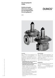
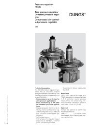
1 1 Ventilgehäuse<br />
2 1 Tellerscheibe<br />
*3 1 Ventilteller<br />
4 1 Ventiltellerau<strong>fh</strong>ängung<br />
5 1 Ring (geteilt)<br />
6 1 Sechskantmutter<br />
7 1 Ventilspindel<br />
8 1 Ventilgehäuseflansch<br />
9 1 Distanzstück<br />
10 1 Spindeldurchführung<br />
11 4Stiftschraube<br />
12 1 Zylinderrohr<br />
13 1 Dichtscheibe<br />
14 1 Federteller<br />
15 1 Federdom<br />
16 1 Federführung<br />
17 1 Verschlußschraube<br />
18 1 Druckfeder<br />
(2 Stck. bei DN 250 u. DN 400/350)<br />
19 8 Sechskantmuttern<br />
20 8 Federringe<br />
21 1 Sechskantmutter<br />
21a 1 Federring<br />
22 1 Schlagdämpfung<br />
23 1 Komplettkolben<br />
24 1 O-Ring<br />
25 1 O-Ring<br />
26 1 O-Ring<br />
27 4Lippenring<br />
28 4Innensechskantschraube<br />
29 4Federring<br />
30 2 O-Ring<br />
31 - Sechskantschraube<br />
32 - Federring<br />
33 1 Flachdichtung<br />
34 1 Abstreifring<br />
35 1 Gewindestift<br />
36 1 O-Ring<br />
*37 1 Ventiltellerdichtung<br />
38 1 Sechskantmutter<br />
39 1 Kerbstift<br />
40 1 Unterlegscheibe<br />
1 valve housing<br />
1 disc washer<br />
1 valve disc<br />
1 valve disc mounting<br />
1 ring (split)<br />
1 hex. nut<br />
1 valve spindle<br />
1 valve housing flange<br />
1 spacer<br />
1 spindle leadthrough<br />
4 stud<br />
1 cylinder barrel<br />
1 sealing washer<br />
1 spring plate<br />
1 spring cap<br />
1 spring guide<br />
1 plug<br />
1 pressure spring<br />
(2 springs for DN 250 and DN 300/400)<br />
8 hex. nut<br />
8 lock washer<br />
1 hex. nut<br />
1 lock washer<br />
impact damper<br />
1 piston assembly<br />
1 o-ring<br />
1 o-ring<br />
1 o-ring<br />
4 lip seal<br />
4 hexagon socket-head screw<br />
4 lock washer<br />
2 o-ring<br />
- hexagon head bolt<br />
- Lock washer<br />
1 gasket<br />
1 wiper seal<br />
1 stud<br />
1 o-ring<br />
1 valve disk seal<br />
1 hex. nut<br />
1 grooved dowel pin<br />
1 washer<br />
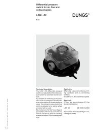
* = Wird als komplette Einheit geliefert (Ventiltellerdichtung im Ventilteller eingeklebt)<br />
* = Will be supplied as a complete unit (valve disc seal bonded into valve disc)<br />
fon: +49-28 37-91 34-0<br />
fax: +49-2837-1444<br />
www.uni-geraete.de<br />
info@uni-geraete.de<br />
seite page 4
… <strong>EPVA</strong> …<br />
=Verschleiß- bzw. Ersatzteile<br />
=Parts subject to wear or replacement.<br />
Änderungen an Maßen und Darstellungen, die<br />
dem technischen Fortschritt dienen, behalten wir<br />
uns vor.<br />
Alterations to dimensions and illustrations in<br />
line with technical progress reserved..<br />
seite page 5<br />
holtumsweg 13<br />
d-47652 weeze<br />
… <strong>EPVO</strong> …<br />
fon: +49-2837-91 34-0<br />
fax: +49-2837-1444<br />
Ventilteller ab DN 80<br />
valve disc from DN 80<br />
www.uni-geraete.de<br />
info@uni-geraete.de
holtumsweg 13<br />
d-47652 weeze<br />
<strong>Typenreihe</strong><br />
Series<br />
Betriebsdruck<br />
Nominal pressure<br />
1-4-<strong>EPVA</strong>...-4<br />
0-1 bar<br />
2-4-<strong>EPVA</strong>...-4<br />
0-2 bar<br />
3-4-<strong>EPVA</strong>...-4<br />
0-3 bar<br />
4-4-<strong>EPVA</strong>...-4<br />
0-4 bar<br />
6-4-<strong>EPVA</strong>...-4<br />
0-6 bar<br />
10-4-<strong>EPVO</strong>...-4R<br />
0-10 bar<br />
10-4-<strong>EPVO</strong>... NH-4R<br />
0–10 bar<br />
# Achtung: Mindeststeuerdruck 5 bar<br />
# Attention: Minimum pressure 5 bar<br />
CE-0085AQ0211<br />
CE-0085AQ0211<br />
CE-0085AQ0211<br />
CE-0085AQ0211<br />
CE-0085AQ0211<br />
CE-0085AQ0211<br />
CE-0085AQ0211<br />
CE-0085AQ0211<br />
CE-0085AQ0211<br />
CE-0085AQ0211<br />
CE-0085AQ0211<br />
CE-0085AQ0211<br />
CE-0085AQ0211<br />
CE-0085AQ0211<br />
CE-0085AQ0211<br />
CE-0085AQ0211<br />
CE-0085AQ0211<br />
CE-0085AQ0211<br />
CE-0085AQ0211<br />
CE-0085AQ0211<br />
CE-0085AQ0211<br />
CE-0085AQ0211<br />
CE-0085AQ0211<br />
CE-0085AS0513<br />
CE-0085AS0513<br />
CE-0085AS0513<br />
CE-0085AS0513<br />
Zur ausführlichen Info bitte Zeichnung Nr. S 6019 anfordern.<br />
For detailed information, please send for drawing No. S 6019<br />
fon: +49-28 37-91 34-0<br />
fax: +49-2837-1444<br />
Prod.ID.Nr./Din<br />
DVGW-Reg. Nr.<br />
Prod. identifikation No./Din<br />
DVGW-Reg.-No.<br />
www.uni-geraete.de<br />
info@uni-geraete.de<br />
Typ<br />
Type<br />
1-4-<strong>EPVA</strong> 30N-4<br />
1-4-<strong>EPVA</strong> 150-4<br />
1-4-<strong>EPVA</strong> 200-4<br />
1-4-<strong>EPVA</strong> 250-4<br />
1-4-<strong>EPVA</strong> 300-4<br />
#1-5-<strong>EPVA</strong> 350-4<br />
1-4-<strong>EPVA</strong> 400-4<br />
2-4-<strong>EPVA</strong> 20N-4<br />
2-4-<strong>EPVA</strong> 25N-4<br />
2-4-<strong>EPVA</strong> 125-4<br />
2-4-<strong>EPVA</strong> 200-4<br />
3-4-<strong>EPVA</strong> 15N-4<br />
3-4-<strong>EPVA</strong> 100-4<br />
4-4-<strong>EPVA</strong> 150-4<br />
6-4-<strong>EPVA</strong> 5N-4<br />
6-4-<strong>EPVA</strong> 7N-4<br />
6-4-<strong>EPVA</strong> 10N-4<br />
6-4-<strong>EPVA</strong> 15N-4<br />
6-4-<strong>EPVA</strong> 20N-4<br />
6-4-<strong>EPVA</strong> 25N-4<br />
6-4-<strong>EPVA</strong> 30N-4<br />
6-4-<strong>EPVA</strong> 100-4<br />
6-4-<strong>EPVA</strong> 125-4<br />
10-4-<strong>EPVO</strong> 7-4R<br />
10-4-<strong>EPVO</strong> 10NH-4R<br />
10-4-<strong>EPVO</strong> 20NH-4R<br />
10-4-<strong>EPVO</strong> 25NH-4R<br />
seite page 6<br />
DN<br />
80<br />
150<br />
200<br />
250<br />
300<br />
350<br />
400<br />
50<br />
65<br />
125<br />
200<br />
40<br />
100<br />
150<br />
15<br />
20<br />
25<br />
40<br />
50<br />
65<br />
80<br />
100<br />
125<br />
Rp3/4<br />
25<br />
50<br />
65<br />
PN<br />
10/16<br />
10/16<br />
10/16<br />
10/16<br />
10/16<br />
10/16<br />
10/16<br />
10/16<br />
10/16<br />
10/16<br />
10/16<br />
10/16<br />
10/16<br />
10/16<br />
10/16<br />
10/16<br />
10/16<br />
10/16<br />
10/16<br />
10/16<br />
10/16<br />
10/16<br />
10/16<br />
-<br />
10/16<br />
10/16<br />
10/16
Antrieb mit Angabe des<br />
Schnellentlüfters<br />
Drive with specification of<br />
quickventing mechanism<br />
KA 70<br />
KA 120*<br />
KA 160**<br />
KA 200**<br />
KA 200**<br />
KA 200**<br />
KA 250**<br />
KA 70<br />
KA 70<br />
KA 120*<br />
KA 200**<br />
KA 70<br />
KA 120*<br />
KA 200**<br />
KA 70<br />
KA 70<br />
KA 70<br />
KA 120*<br />
KA 120*<br />
KA 120*<br />
KA 160*<br />
KA 160*<br />
KA 200**<br />
KA 70<br />
KA 70<br />
KA 120*<br />
KA 120*<br />
Luftverbauch je<br />
Schaltung bei 4 bar<br />
Air consumption per<br />
cyle at 4 bar<br />
1 NL<br />
5 NL<br />
10 NL<br />
17 NL<br />
17 NL<br />
22 NL#<br />
27 NL<br />
1 NL<br />
1 NL<br />
5 NL<br />
17 NL<br />
1 NL<br />
5 NL<br />
17 NL<br />
1 NL<br />
1 NL<br />
1 NL<br />
5 NL<br />
5 NL<br />
5 NL<br />
10 NL<br />
10 NL<br />
17 NL<br />
1 NL<br />
1 NL<br />
5 NL<br />
5 NL<br />
seite page 7<br />
Steuerventil<br />
Control valve<br />
10-EVD 2/2401<br />
10-EVD 2/2401<br />
10-EVD 2/2401<br />
10-EVD 2/2401<br />
10-EVD 2/2401<br />
10-EVD 2/2401<br />
10-EVD 2/2401<br />
10-EVD 2/2401<br />
10-EVD 2/2401<br />
10-EVD 2/2401<br />
10-EVD 2/2401<br />
10-EVD 2/2401<br />
10-EVD 2/2401<br />
10-EVD 2/2401<br />
10-EVD 2/2401<br />
10-EVD 2/2401<br />
10-EVD 2/2401<br />
10-EVD 2/2401<br />
10-EVD 2/2401<br />
10-EVD 2/2401<br />
10-EVD 2/2401<br />
10-EVD 2/2401<br />
10-EVD 2/2401<br />
10-EVD 2/2401<br />
10-EVD 2/2401<br />
10-EVD 2/2401<br />
10-EVD 2/2401<br />
* =SchnellentlüfterRP 1/4 ** =SchnellentlüfterRp 1/2<br />
* =Quick-venting mechanism Rp 1/4 ** = Quick-venting mechanism Rp 1/2<br />
Gewicht in kg<br />
Weight in kg<br />
23,5<br />
82,5<br />
155<br />
267<br />
390<br />
590<br />
980<br />
20,5<br />
21,5<br />
65<br />
201<br />
17,5<br />
47,5<br />
138<br />
8<br />
8,5<br />
9,95<br />
24<br />
26,8<br />
31,7<br />
43,5<br />
54<br />
118<br />
7,2<br />
10<br />
33,5<br />
38<br />
holtumsweg 13<br />
d-47652 weeze<br />
A B C<br />
310<br />
480<br />
600<br />
730<br />
850<br />
980<br />
1100<br />
230<br />
290<br />
400<br />
600<br />
200<br />
350<br />
480<br />
130<br />
150<br />
160<br />
200<br />
230<br />
290<br />
310<br />
350<br />
400<br />
95<br />
160<br />
230<br />
290<br />
fon: +49-28 37-91 34-0<br />
fax: +49-2837-1444<br />
395<br />
575<br />
695<br />
785<br />
830<br />
910<br />
980<br />
365<br />
385<br />
565<br />
735<br />
355<br />
520<br />
680<br />
340<br />
340<br />
350<br />
460<br />
470<br />
485<br />
565<br />
580<br />
645<br />
317<br />
360<br />
490<br />
520<br />
105<br />
170<br />
210<br />
265<br />
265<br />
265<br />
370<br />
105<br />
105<br />
170<br />
265<br />
105<br />
170<br />
265<br />
105<br />
105<br />
105<br />
170<br />
170<br />
170<br />
210<br />
210<br />
265<br />
105<br />
105<br />
170<br />
170<br />
www.uni-geraete.de<br />
info@uni-geraete.de
130.000.002-00<br />
holtumsweg 13<br />
d-47652 weeze<br />
Lieferprogramm Production programme<br />
Notizen / Note<br />
<strong>elektro</strong>-magnetventile<br />
<strong>elektro</strong>-<strong>pneumatikventile</strong><br />
mengen-regelklappen<br />
mengen-regelschieber<br />
mengen-einstellarmaturen<br />
sonderarmaturen<br />
fon: +49-28 37-91 34-0<br />
fax: +49-2837-1444<br />
www.uni-geraete.de<br />
info@uni-geraete.de<br />
seite page 8<br />
electro-magnetic-valves<br />
electro-pneumatic-valves<br />
volume-regulating-butterfly-valves<br />
flow-control-valves<br />
flow-adjusting-valves<br />
special fittings