MONTAGEANLEITUNG - DEHN (UK)
MONTAGEANLEITUNG - DEHN (UK)
MONTAGEANLEITUNG - DEHN (UK)

Sie wollen auch ein ePaper? Erhöhen Sie die Reichweite Ihrer Titel.
YUMPU macht aus Druck-PDFs automatisch weboptimierte ePaper, die Google liebt.
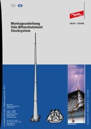
<strong>MONTAGEANLEITUNG</strong><br />
UP-Trennstellenkästen (Art.-Nr. 476 010 / 476 016) Bild 1 UP-Trennstellenkästen<br />
1. Anwendung<br />
Diese UP-Trennstellenkästen (Bild 1) eignen sich für den Betonbau B und sind der Schalungstechnik angepasst.<br />
Die UP-Trennstellenkästen werden vorwiegend im Zuge der Schalungsarbeiten montiert.<br />
2. Anschluss mit der Ableitung oder der Erdungsanlage<br />
2.1 Variante A: - mit starren Anschlussfahnen 1 (Rd 8 mm) und 2 (Rd 10 mm) ca. 200 mm lang.<br />
- Die Anschlussfahnen sind teilisoliert um eine evtl. Zufallsverbindung zur Armierung zu verhindern.<br />
- Die beiden Anschlussfahnen 1 (Rd 8 mm) und 2 (Rd 10 mm) werden mittels geeigneter Klemmen mit<br />
der Ableitung oder der Erdungsanlage verbunden.<br />
2.2 Variante B: - mit flexiblen Anschlussleitungen 1 aus Cu (16mm2 ) und Kabelschuh aus Cu/galSn (Bohrung 10,5 mm).<br />
- Die Anschlussleitungen sind isoliert um eine evtl. Zufallsverbindung zur Armierung zu verhindern.<br />
- Die beiden Anschlussleitungen 1 werden mittels geeigneter Klemmen mit der Ableitung oder der<br />
Erdungsanlage verbunden.<br />
3. Montage im Beton<br />
Bei der Montage der UP-Trennstellenkästen sind nachfolgende Punkte zu beachten (siehe Bilder 2.1 - 2.3):<br />
3.1 - Niro-Deckel (4 Befestigungsschrauben) entfernen.<br />
- UP-Trennstellenkanten (ohne Niro-Deckel) an der gewünschten Stelle mit der Aufschrift "Vorderseite" an<br />
Innenschalung schrauben oder nageln.<br />
- Variante A: Ableitung mit der Anschlussfahne 1 und Erdungsanlage mit der Anschlussfahne 2 verbinden<br />
(Verbindung z.B. mit Parallelverbinder, Art.-Nr. 305 000).<br />
- Variante B: Ableitung und Erdungsanlage mit den flexiblen Anschlussleitungen verbinden (Verbindung z.B. mit<br />
KS-Verbinder, Art.-Nr. 301 009).<br />
- Armier- und Betonarbeiten wie gewohnt fortführen.<br />
3.2 - Schalung entfernen.<br />
- Kunststoffdeckel mit Aufschrift "Vorderseite" mittels scharfkantigem Messer oder geeignetem Werkzeug herausschneiden<br />
(Schnittlinien sind vorgezeichnet).<br />
- Trennstelle wird sichtbar.<br />
- Festen Sitz der Trennstellenschrauben kontrollieren.<br />
3.3 - Niro-Deckel mittels Schrauben wieder befestigen (Beschriftung "Blitzschutz-Trennstelle" muss vorne sichtbar sein).<br />
- Bei dickeren Putzschichten können die mitgelieferten Schrauben gegen Schrauben mit einer um 1 bis 2 cm größeren<br />
Länge ausgewechselt werden.<br />
4. Montage z.B im Wärmedämm-Verbundssystem<br />
Bei der Montage (Bild 3) auf einem Mauerwerk z.B. in einem Wärmedämm-Verbundsystem sind nachfolgende Punkte zu<br />
beachten.<br />
4.1 - Der UP-Trennstellenkasten kann mit dem Befestigungswinkel (Art.-Nr. 106 310) in Kombination mit einer<br />
Flachrundschraube montiert werden.<br />
- Niro-Deckel (4 Befestigungsschrauben) entfernen.<br />
- Position der seitlichen Löcher für die Flachrundschrauben je nach Aufbau des Wärmedämm-Verbundsystems ermitteln.<br />
Geeignet für Aufbauten des Wärmedämm-Verbundsystems von ca. 105 bis 128 mm.<br />
- Bohrung seitlich am Steg des UP-Trennstellenkasten mit Durchmesser 10,5 mm erstellen.<br />
- Befestigungswinkel mittels Flachrundschraube M 10 x 30 mm am Trennstellenkasten montieren.<br />
4.2 - Montagebohrungen für Befestigungswinkel (Lochdurchmesser 11 mm) im Mauerwerk erstellen.<br />
- Befestigungswinkel montieren und UP-Trennstellenkasten entsprechend dem Aufbau positionieren.<br />
- Unter dem Gesichtspunkt der Wärmedämmung und der mechanischen Festigkeit wird empfohlen, hinter dem<br />
UP-Trennstellenkasten einen Abschnitt / Teil der Dämmung zu installieren.<br />
4.3 - Ableitung und Erdungsanlage mit den flexiblen Anschlussleitungen verbinden.<br />
- Kunststoffdeckel mit Aufschrift "Vorderseite" mittels scharfkantigem Messer oder geeignetem Werkzeug herausschneiden<br />
(Schnittlinien sind vorgezeichnet).<br />
- wie unter 3.3 beschrieben weiter verfahren.<br />
<strong>DEHN</strong> + SÖHNE<br />
Hans-Dehn-Str. 1<br />
Postfach 1640<br />
92306 Neumarkt<br />
Tel: 09181 / 906 - 0<br />
Fax: 09181 / 906 - 333<br />
www.dehn.de<br />
info@dehn.de<br />
Variante A<br />
Art.-Nr. 476 010<br />
1 Anschlussfahne (Rd 8 mm)<br />
2 Anschlussfahne (Rd 10 mm)<br />
Schalung<br />
Bild 2 Montage im Beton<br />
Beton<br />
VORDERSEITE<br />
VORDERSEITE<br />
Variante B<br />
Art.-Nr. 476 016<br />
1 flexible Anschlussleitung (Cu 16mm 2 )<br />
mit Kabelschuh (Cu/galSn)<br />
2.1 2.2 2.3<br />
Mauerwerk<br />
Dämmung<br />
Beton<br />
Bild 3 Montage z.B. im Wärmedämm-Verbundssystem<br />
Befestigungswinkel<br />
Art.-Nr. 106 310<br />
Publication No. 1020 / UPDATE 02.09 / Id No. 039430<br />
Befestigungswinkel<br />
Art.-Nr. 106 310<br />
Flachrundschraube<br />
M 10 x 30 mm<br />
© COPYRIGHT 2008 <strong>DEHN</strong> + SÖHNE/ protected by ISO 16016<br />
105-128 mm<br />
Beton<br />
Blitzschutz<br />
Trennstelle<br />
35-58 mm<br />
English<br />
Version<br />
p.t.o.
1. Use<br />
INSTALLATION INSTRUCTIONS Publication No. 1020 / UPDATE 02.09 / Id No. 039430<br />
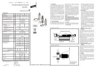
UP Inspection Housings (Part No. 476 010 / 476 016) Figure 1 UP inspection housings<br />
These UP inspection housings (Fig. 1) are suitable for concrete structures B and are adapted to the formwork technology.<br />
In the majority of cases, UP inspection housings are installed during formwork work.<br />
2. Connection to the down conductor or the earth-termination system<br />
2.1 Type A: - with rigid terminal lugs 1 (Rd 8 mm) and 2 (Rd 10 mm) of a length of approx. 200 mm.<br />
- The terminal lugs are partly insulated in order to prevent accidental contact with the reinforcement.<br />
- The two terminal lugs 1 (Rd 8 mm) and 2 (Rd 10 mm) are connected to the down conductor or the<br />
earth-termination system by means of the appropriate terminals.<br />
2.2 Type B: - With flexible copper connecting cables 1 (16 mm2) and cable lug made of Cu/galSn (hole 10.5 mm).<br />
- The connecting cables are insulated in order to prevent accidental contact with the reinforcement.<br />
- The two connecting cables 1 are connected to the down conductor or the earth-termination system by<br />
means of the appropriate terminals.<br />
3. Installation in concrete<br />
When installing UP inspection housings, the following points have to be observed (see Fig. 2.1 to 2.3):<br />
3.1 - Remove the stainless steel cover (four fixing screws).<br />
- Screw or nail the UP inspection housing (without stainless steel cover) labelled ”Vorderseite” (front) at the desired<br />
location of the inner formwork.<br />
- Type A: Connect the down conductor to terminal lug 1 and the earth-termination system to terminal lug 2 (connection<br />
e.g. via parallel connector Part No. 305 000).<br />
- Type B: Connect the down conductor and the earth-termination system to the flexible connecting cables (connection<br />
e.g. via KS connector Part No. 301 009)<br />
- Continue reinforcement and concrete work as usual.<br />
3.2 - Remove the formwork.<br />
- Use a sharp knife or another suitable tool to cut out the plastic cover labelled ”Vorderseite” (front) (cutting line is<br />
predetermined).<br />
- Test joint becomes visible.<br />
- Ensure that the screws of the test joint are firmly tightened.<br />
3.3 - Attach stainless steel cover again using the screws (”Blitzschutz-Trennstelle” (lightning protection test joint) must<br />
be visible).<br />
- In case of thick plaster layers the screws included in delivery can be replaced by screws which are 1 to 2 cm longer.<br />
4. Installation e.g. in a thermal insulation composite system<br />
The following points have to be observed when installing UP inspection housings (Fig. 3) on brickwork e.g. in a thermal<br />
insulation composite system:<br />
4.1 - The UP inspection housing can be installed using an angled fixing plate (Part No. 106 310) and a truss head screw.<br />
- Remove the stainless steel cover (4 fixing screws).<br />
- Determine the position of the lateral holes for the truss head screws depending on the composition of the thermal<br />
insulation composite system.<br />
Suitable for a composition of the thermal insulation composite system of approximately 105 to 128 mm.<br />
- Drill a hole with a diameter of 10.5 mm at the web on the side of the inspection housing.<br />
- Install the angled fixing plate on the UP inspection housing using the truss head screw M 10 x 30 mm.<br />
4.2 - Drill a hole for the installation of the angled fixing plate (hole diameter 11 mm) in the brickwork.<br />
- Install the angled fixing plate and position the UP inspection housing according to the composition of the thermal<br />
insulation composite system.<br />
- It is advisable to install a section/part of the insulation behind the UP inspection housing to improve heat insulation<br />
performance and mechanical strength.<br />
4.3 - Connect the down conductor and the earth-termination system to the flexible connecting cables.<br />
- Use a sharp knife or another suitable tool to cut out the plastic cover labelled ”Vorderseite” (front) (cutting line is<br />
predetermined).<br />
- Continue as described in 3.3.<br />
<strong>DEHN</strong> + SÖHNE<br />
Hans-Dehn-Str. 1<br />
Postfach 1640<br />
92306 Neumarkt<br />
Tel: 09181 / 906 - 0<br />
Fax: 09181 / 906 - 333<br />
www.dehn.de<br />
info@dehn.de<br />
Type A<br />
Part No. 476 010<br />
1 terminal lug (Rd 8 mm)<br />
2 terminal lug (Rd 10 mm)<br />
formwork<br />
Figure 2 Installation in concrete<br />
concrete<br />
VORDERSEITE<br />
VORDERSEITE<br />
Type B<br />
Part No. 476 016<br />
1 flexible connecting cable (Cu 16mm 2 )<br />
with cable lug (Cu/galSn)<br />
2.1 2.2 2.3<br />
brickwork<br />
insulation<br />
concrete<br />
Figure 3 Installation e.g. in a thermal insulation composite system<br />
angled fixing plate<br />
Part No. 106 310<br />
angled fixing plate<br />
Part No. 106 310<br />
truss head screw<br />
M 10 x 30 mm<br />
© COPYRIGHT 2008 <strong>DEHN</strong> + SÖHNE/ protected by ISO 16016<br />
105-128 mm<br />
concrete<br />
Blitzschutz<br />
Trennstelle<br />
35-58 mm<br />
German<br />
Version<br />
p.t.o.