Montage-_Bedienungs-_Wartungsanleitung_systeQ-M-M-B2H-ESC
Montage-_Bedienungs-_Wartungsanleitung_systeQ-M-M-B2H-ESC
Montage-_Bedienungs-_Wartungsanleitung_systeQ-M-M-B2H-ESC

Erfolgreiche ePaper selbst erstellen
Machen Sie aus Ihren PDF Publikationen ein blätterbares Flipbook mit unserer einzigartigen Google optimierten e-Paper Software.
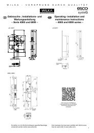
Installation and fixing instructions<br />
• Applicable for 1- and 2-leafed elements made of PVC,<br />
timber, aluminium and steel.<br />
• The sash and frame must run parallel to each other over the<br />
entire height; max. 4 mm warpage is permissible.<br />
• On double-leafed doors, check that the interlocking door<br />
leafs warrant the simultaneous opening of both leafs<br />
(force-opening). In the same way check that the controls<br />
(e.g. panic bars, lever-handles) are not blocking each<br />
other. The use of a connector flap is necessary for moving<br />
the active leaf.<br />
• Main-lock casing routing in accordance with the drawing.<br />
• The routing for the profile cylinder and lever-handle must<br />
be aligned.<br />
• Never carry out hardware drilling work with the lock<br />
installed.<br />
• Before installing the lock, all impurities are to be removed<br />
from the routed area e.g. swarf.<br />
• Screw fix faceplates and strikers with Ø 4 mm screws, their<br />
length adapted to the profile system.<br />
• The installation screws must be screwed in at a right angle<br />
to the faceplate.<br />
• Upon tightening the faceplate screws, ensure that the<br />
connecting-rods can move freely.<br />
• Observe the exact location of the strikers in accordance<br />
with the drawing, in order to warrant secure engagement<br />
of the locking system.<br />
• Ensure that both the latch and all locking components close<br />
softly.<br />
• Door gaskets (e.g. profile gaskets, floor gaskets) may not<br />
have an effect on the smooth operation and stipulated<br />
function of the emergency exit doorlock.<br />
• Remove the cylinder transport protection only shortly<br />
before the installation of the cylinder.<br />
• Use a non-restricted profile cylinder with cylinder-cam<br />
forced decoupling! The cylinder must be marked with ‘FZG’.<br />
• Never resort to violent measures in the event of arduous<br />
operation after installing the lock! Instead find out the reason<br />
and fix it.<br />
• When transporting doors – also when the lock is locked –<br />
protect the door leaf against permanent dislocation.<br />
• When using a panic push bar, its rotary motion must be<br />
lined up with the spindle receiver hole (72/92 mm PC<br />
centres: 35° rotary motion).<br />
• The fixing of panic and/or emergency exit locks can differ<br />
depending on the door material. In order to mount panic<br />
bars and lever handles reliably, through bolts should be use.<br />
• If a door closer is installed, one should take into account<br />
that children, disabled persons and elderly people operating<br />
the door are not unnecessarily hindered.<br />
• If panic/emergency exit locks are to be fixed on doubleleafed<br />
doors with rebated centre mullion and door closers,<br />
an operating sequence control device in accordance with<br />
EN 1158 should be installed in order to warrant the correct<br />
operating sequence the door (particularly important on fire<br />
protection/smoke protection doors).<br />
• Before installing a fire protection/smoke protection door,<br />
ensure that the emergency exit doorlock is suitable for that<br />
particular door.<br />
• If the emergency exit doorlocks are to be mounted on<br />
glazed doors, care must be taken to ensure that the glass<br />
parts are safety glass or laminated safety glass.<br />
• Panic/emergency exit locks are not suitable for use on<br />
swing doors.<br />
• Panic push bars or lever handles are usually installed at<br />
a height of between 900 mm and 1100 mm above the<br />
surface of the finished floor (with the door closed). If it<br />
is known that the majority of the users in a building are<br />
small children, a reduction of the height the bar should be<br />
considered.<br />
• On panic exit hardware the panic push bar<br />
should be installed in order to achieve the<br />
most effective rod length.<br />
• Upon installing emergency exit locks with<br />
lever handle operation (particularly on doors<br />
with stepped surfaces), any possible safety<br />
hazards (e.g. trapped fingers or clothes)<br />
should be avoided as far as possible.<br />
• A pictogram with opening information should<br />
be attached to the inside of exit doors.<br />
7<br />
GB DE