Trumatic S 3002 FS
Trumatic S 3002 FS
Trumatic S 3002 FS

Erfolgreiche ePaper selbst erstellen
Machen Sie aus Ihren PDF Publikationen ein blätterbares Flipbook mit unserer einzigartigen Google optimierten e-Paper Software.
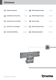
Warm air distribution<br />
The warm air is drawn in by the Trumavent fan (35) and led<br />
mainly into the floor area via two warm air outlets at the air<br />
distributor (37) via flexible pipes (36).<br />
If necessary, remove ridges<br />
(38) at warm air outlet<br />
(allows heater to be pulled<br />
forward, even with fixed<br />
warm air pipe routing).<br />
The 2 connections at the<br />
warm air distributor (37)<br />
are designed for the Truma<br />
dia. 65 mm ÜR and dia.<br />
72 mm VR fan ducts.<br />
The fan ducts slide firmly<br />
into / onto the warm air<br />
connections. If original<br />
pressure-proof Truma fan<br />
ducts are not used, the<br />
ducts must be prevented<br />
from slipping out of the<br />
warm air connections with<br />
two dia. 2.9 mm sheet<br />
metal screws.<br />
16<br />
38<br />
36<br />
37 37<br />
39<br />
38<br />
A warm air pipe must be connected to each warm air<br />
outlet (with several air outlets if necessary).<br />
If the fan ducts are of different lengths or at sides with differing<br />
heating requirements, the dia. 72 mm fan duct must be<br />
used. This allows the full air capacity to be used at this side.<br />
The quantity of air can be individually increased by adjusting<br />
the air flap (39). This reduces the air capacity at the other side.<br />
The warm air system is individually designed for each<br />
installation using a modular principle. A wide range of<br />
accessories is available for this purpose.<br />
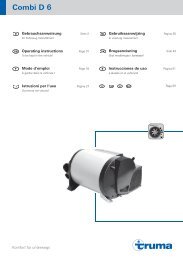
Electrical connection<br />
Trumavent fan (12 V)<br />
Prior to working on electric components the appliance<br />
must be disconnected from the power supply. Switching<br />
off at the control panel is not sufficient!<br />
The plug-in connection<br />
K only applies to<br />
the <strong>Trumatic</strong> S <strong>3002</strong> K and<br />
S 5002 K heaters and is not<br />
used.<br />
Connect device to a fuseprotected<br />
12 V (5 – 10 A)<br />
power supply using a<br />
2 x 1.5 mm² cable, or a<br />
2 x 2.5 mm² for distances<br />
exceeding 6 metres.<br />
When connecting directly to the battery, fuse the plus and<br />
minus line. Connect with faston terminals (40), fully insulated<br />
(motor vehicle flat connector system 6.3 mm).<br />
If the connections are interchanged there is a risk<br />
of cables burning. Fur thermore, this rules out any<br />
guarantee or liability claim.<br />
When power packs or power supply units are being used,<br />
note that the output voltage is between 11 V and 15 V and the<br />
alternating current ripple is < 1.2 Vpp.<br />
K<br />
40<br />
35<br />
36<br />
Connecting 230 V<br />
The Trumavent fan TEB can also be operated with<br />
230 V – by using the Truma voltage converter SPU (part<br />
no. 40000-47700). The assembly of the SPU voltage converter<br />
should be as close to the floor as possible. It is not possible to<br />
connect further 12 V appliances to this voltage converter.<br />
When power packs or power supply units are being<br />
used, note that the output voltage is between 11 V and<br />
15 V and the alternating current ripple is< 1.2 Vpp. The Truma<br />
battery charger NT12/ 3-18 (part no. 39901-01) is recommended<br />
for connecting multiple 12 V devices. This charger (with a<br />
charging current of 18 A) is suitable for charging lead-acid or<br />
lead-gel batteries.<br />
Cable routing<br />
Attach edge protection profiles (41) in the warm air outlets at<br />
the heater box for leading cables through and route all cables<br />
(12 V and 230 V) to the outside together with the warm air pipe.<br />
41<br />
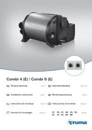
Attaching the heater<br />
1. Place heater at intended installation site at a slight angle.<br />
2. Insert the flue gas pipe (28) through the opening (20) into<br />
the inner installation box. Attach the combustion air supply<br />
pipe (1) to the connection (43) using a worm drive hose<br />
clip (42) and slide the condensate hose (32) through the<br />
hole (34) in the floor without kinking, descending along its<br />
entire length.<br />
44<br />
32<br />
43<br />
34<br />
42<br />
1<br />
41<br />
20<br />
28<br />
3. Then push the heater box against the outer wall and firmly<br />
secure with 6 screws (44).<br />
When screwing on the heater box, please ensure that<br />
no hoses or pipes are trapped or kinked.