Einbauanleitung - DEHN (UK)
Einbauanleitung - DEHN (UK)
Einbauanleitung - DEHN (UK)

Sie wollen auch ein ePaper? Erhöhen Sie die Reichweite Ihrer Titel.
YUMPU macht aus Druck-PDFs automatisch weboptimierte ePaper, die Google liebt.
Technische Daten<br />
Druckschrift Nr. 1068/ DE / STAND 02.11 Id.-Nr. 064004<br />
Überspannungsfeinschutzgerät<br />
Typ UGKF ...<br />
<strong>DEHN</strong> + SÖHNE GMBH + CO. KG. Hans-Dehn-Str. 1<br />
Postfach 1640<br />
92306 Neumarkt<br />
Germany<br />
www.dehn.de Tel: +49 9181 906-0<br />
info@dehn.de Fax: +49 9181 906-100<br />
EINBAUANLEITUNG<br />
Typ UGKF/... BNC N L B L<br />
Nennspannung UN 5 V DC –8 V DC/+1 V DC<br />
Ableiter-Bemessungsspannung Uc<br />
(max. zul. Betriebsspannung) 8 V DC –10 V DC/+1,4 V DC<br />
Nennableitstoßstrom (8/20) isn 2,5 kA (A/Schirm)<br />
10 kA (Schirm/PG)<br />
erhöhter Ableitstoßstrom (8/20) Imax 5 kA (A/Schirm)<br />
20 kA (Schirm/PG)<br />
Schutzpegel<br />
– Restspannung bei isn<br />
Up<br />
(A/Schirm)<br />
– Ansprechspannung bei 1 kV/µs<br />
25 V 20V 35 V<br />
(A/Schirm) 13 V 15 V<br />
(Ader oder Schirm/PG) 600 V<br />
Ansprechzeit tA 1 ns (A/Schirm)<br />
100 ns (Schirm/PG)<br />
Grenzfrequenz (50 -System) fG 300 MHz 90 MHz 300 MHz<br />
für Datenübertragungs vs<br />
geschwindigkeit bis 16 MBit/s<br />
Längsimpedanz/Ader R 10 1 <br />
Rückfl ussdämpfung aR 20 dB 20 dB 20 dB<br />
(bezogen auf 50 ) (bis 40 MHz) (bis 20 MHz) (bis 100 MHz)<br />
Einfügungsdämpfung aE 1 dB 1 dB 0,5 dB<br />
(50 -System) (bis 40 MHz) (bis 35 MHz) (bis 100 MHz)<br />
3 dB 3 dB 1 dB<br />
(bis 300 MHz) (bis 90 MHz) (bis 190 MHz)<br />
3 dB<br />
(bis 300 MHz)<br />
Anschlüsse Eingang (Buchse) BNC N BNC<br />
Ausgang (Stecker) BNC N BNC<br />
Erdung des Schirmes indirekt über integrierte Funkenstrecke<br />
und herausgeführte Erdungsleitung<br />
0,75mm2 , 0,3m lang<br />
Zubehör Isolierhülse<br />
Abmessung Ø 24 mm, 25 mm, Ø 24 mm,<br />
74 mm lang 90 mm lang 74 mm lang<br />
Art.-Nr. 929 010 929 012 929 017<br />
© COPYRIGHT 2011 <strong>DEHN</strong> + SÖHNE/protected by ISO 16016<br />
© COPYRIGHT 2004 <strong>DEHN</strong> + SÖHNE<br />
1. Anwendung<br />
Das Überspannungsfeinschutzgerät Typ UGKF<br />
wird mittels beidseitiger Anschlüsse direkt in<br />
den Leitungszug des zu schützenden Systems/<br />
Gerätes geschaltet. Die Überspannungsschutzbeschaltung<br />
hat eine Ventilcharakteristik, d. h.<br />
das UGKF wird so eingebaut, dasss der am<br />
Typenschild angegebene Ausgang ( protected)<br />
im Leitungszug dem zu schützenden Gerät<br />
zugewandt ist. Ein- und Ausgang dürfen nicht<br />
vertauscht werden. Der Einbau des Schutzgerätes<br />
ist möglichst nahe am zu schützenden Gerät<br />
vorzunehmen.<br />
Das Überspannungsschutzgerät ist im Rahmen<br />
des Blitz-Schutzzonen-Konzeptes (siehe auch<br />
DIN V VDE V 0185:... / IEC 61312-1:...) am Blitz-<br />
Schutzzonen-Übergang 1 auf 2 oder unmittelbar<br />
vor dem zu schützenden Gerät einzubauen.<br />
2. Sicherheitshinweise<br />
Das Überspannungsschutzgerät darf nur von<br />
einer Elektrofachkraft unter Berücksichtigung<br />
der DIN VDE-Bestimmungen montiert werden.<br />
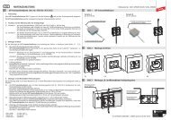
Einbaubeispiel Typ UGKF N L<br />
Schutzrohr<br />
Einbaubeispiel Typ UGKF B L<br />
T-Verbinder<br />
Sein Einsatz ist nur im Rahmen der in dieser<br />
<strong>Einbauanleitung</strong> genannten und gezeigten<br />
Bedingungen zulässig.<br />
Bei Belastungen, die über den ausgewiesenen<br />
Werten liegen, z. B. durch einen direkten Blitzeinschlag,<br />
können das Überspannungsschutzgerät<br />
und das angeschlossene Gerät zerstört werden.<br />
Vor dem Einbau ist das Überspannungsschutzgerät<br />
durch die Elektrofachkraft auf äußere<br />
Beschädigungen zu kontrollieren. Sollte bei dieser<br />
Kontrolle eine Beschädigung oder ein sonstiger<br />
Mangel festgestellt werden, darf das Überspannungsschutzgerät<br />
nicht eingebaut werden.<br />
Achtung:<br />
Öffnen Sie niemals das Gerät !<br />
Durch das Öffnen des Gerätes oder jeden sonstigen<br />
Geräteeingriff kann die Schutzschaltung<br />
zerstört werden. Bei Geräteeingriff erlischt die<br />
Gewährleistung.<br />
3. Erdung<br />
Die Erdung ist auf kürzestem Wege vorzunehmen.<br />
Das Schutzgerät kann wie folgt geerdet werden:<br />
3.1 Direkte Erdung<br />
Montageschirmklemme<br />
ÜGKF/N-L UGKF N L<br />
Buskoppler Montageplatte<br />
ÜGKF/B-L UGKF B L<br />
Schnittstellenkarte<br />
am Computer<br />
Das Gehäuse des UGKF ist direkt mit dem<br />
Schirm des Koaxialkabels verbunden. Dadurch<br />
kann der Schirm direkt geerdet werden,<br />
indem das UGKF - Gehäuse mittels einer<br />
Rohrschelle (z. B. Art.-Nr. 540 001) geerdet<br />
wird. In diesem Fall bleibt die herausgeführte<br />
Erdungsleitung unbenutzt.<br />
3.2 Indirekte Erdung<br />
Diese Maßnahme wird mittels der isoliert<br />
aus dem UGKF-Gehäuse herausgeführten<br />
Erdungsleitung durchgeführt. Hiermit kann<br />
der Schirm des Koaxialkabels erdfrei betrieben<br />
werden (z. B. zur Vermeidung von Brummschleifen).<br />
Die Erdungsleitung des UGKF ist<br />
mit dem Gehäuse/Masse des zu schützenden<br />
Gerätes zu verbinden.<br />
Bei dieser Anwendung ist zu beachten, dass<br />
das zu schützende Gerät zwischen Elektronik<br />
und Masse eine Spannungsfestigkeit von<br />
mindestens 1,5 kV aufweisen muss. Um<br />
diesen Wert schutztechnisch sicherzustellen,<br />
darf die Erdungsleitung des UGKF keinesfalls<br />
verlängert werden.<br />
Bei zu schützenden Geräten der Schutzklasse<br />
II ist die Erdungsleitung des UGKF mit<br />
dem nächstgelegenen Potentialausgleich zu<br />
verbinden.<br />
4. Besondere Einbauhinweise für<br />
UGKF N L<br />
Diese Ausführung ist zum Schutz von LAN-<br />
Schnittstellen entsprechend IEEE 802.3 mit<br />
N-Connector-Anschluss (Ethernet/10 Base 5)<br />
konzipiert.<br />
Das Schutzgerät wird direkt am Buskoppler<br />
angeschraubt (siehe Einbaubild). Die Erdungsleitung<br />
des UGKF N L wird unmittelbar mit der<br />
Montageschirmklemme oder Schirmklemme der<br />
Montageplatte verbunden.<br />
Über das Schutzgerät ist der mitgelieferte<br />
Isolationsschutz (Rohr) so anzubringen, dass<br />
ein unbeabsichtigtes Erden oder Berühren mit<br />
potentialfremden Systemteilen nicht möglich ist.<br />
Der Isolationsschutz ist nach der Montage mit der<br />
Arretierschraube zu fi xieren.<br />
5. Besondere Einbauhinweise für<br />
UGKF B L<br />
Diese Ausführung ist zum Schutz von LAN-<br />
Schnittstellen entsprechend IEEE 802.3 mit<br />
BNC-Connector-Anschluss (Cheapernet/10 Base<br />
2) konzipiert.<br />
Das Schutzgerät wird direkt an der Schnittstellenkarte<br />
des Computers (siehe Einbaubeispiel)<br />
angeschraubt. Die Erdungsleitung des UGKF B L<br />
ist unmittelbar mit dem Gehäuse des Computers<br />
zu verbinden.<br />
6. Wartung<br />
Soweit vorgenannte Einbaubedingungen eingehalten<br />
und die Nenndaten nicht überschritten<br />
werden, ist das Überspannungsschutzgerät über<br />
lange Zeit wartungsfrei.<br />
Eine Kontrolle ist deshalb nur im Zusammenhang<br />
mit routinemäßigen Wartungsarbeiten an der<br />
Anlage notwendig.
Technical Data<br />
Publication No. 1068 / GB / UPDATE 02.11 Id. No. 064004<br />
<strong>DEHN</strong> + SÖHNE GMBH + CO. KG. Hans-Dehn-Str. 1<br />
P.O. Box 1640<br />
92306 Neumarkt<br />
Germany<br />
www.dehn.de Tel: +49 9181 906-0<br />
export@dehn.de Fax: +49 9181 906-100<br />
Overvoltage Fine Protector<br />
Type UGKF ...<br />
INSTALLATION INSTRUCTIONS<br />
Type UGKF/... BNC N L B L<br />
nominal voltage UN 5 V DC –8 V DC/+1 V DC<br />
rated voltage (maximum Uc<br />
continuous operating voltage) 8 V DC –10 V DC/+1.4 V DC<br />
nominal discharge current (8/20) isn 2.5 kA (A/shield)<br />
10 kA (shield/PG)<br />
max. discharge current (8/20) Imax 5 kA (A/shield)<br />
20 kA (shield/PG)<br />
voltage protection level<br />
– residual voltage at isn<br />
Up<br />
(A/shield)<br />
– at 1 kV/µs<br />
25 V 20V 35 V<br />
(A/shield) 13 V 15 V<br />
(line or shield/PG) 600 V<br />
response time tA 1 ns (A/shield)<br />
100 ns (shield/PG)<br />
bandwidth (50 -system) fG 300 MHz 90 MHz 300 MHz<br />
for data transmission vs<br />
rates up to 16 Mbit/s<br />
series impedance/line R 10 1 <br />
return loss aR 20 dB 20 dB 20 dB<br />
(matched to 50 ) (to 40 MHz) (to 20 MHz) (to 100 MHz)<br />
insertion loss aE 1 dB 1 dB 0,5 dB<br />
(50 -system) (to 40 MHz) (to 35 MHz) (to 100 MHz)<br />
3 dB 3 dB 1 dB<br />
(to 300 MHz) (to 90 MHz) (to 190 MHz)<br />
3 dB<br />
(to 300 MHz)<br />
connections input (jack) BNC N BNC<br />
output (connector) BNC N BNC<br />
earthing of shield indirectly via built-in spark gap<br />
and external 0.75mm2 earthing<br />
conductor, 0.3m long<br />
accessories insulat.<br />
sleeve<br />
dimensions Ø 24 mm, 25 mm, Ø 24 mm,<br />
74 mm long 90 mm long 74 mm long<br />
art. no. 929 010 929 012 929 017<br />
UL requirements<br />
1. This device are intended for ordinary indoor<br />
us on communication loop circuits that are<br />
isolated from the Public Switched Telephone<br />
Network.<br />
2. The protector shall be secured using the<br />
methods described in this instruction.<br />
3. Proper grounding continuity shall be<br />
determined.<br />
4. Please install the protector in accordance<br />
with the applicable requirements of the<br />
National Electrical Code, Article 800 or<br />
other applicable local codes.<br />
5. The maximum circuit current for UL 497 B<br />
applications is limited to 100 mA.<br />
© COPYRIGHT 2004 <strong>DEHN</strong> + SÖHNE<br />
1. Application<br />
The type UGKF overvoltage fi ne protector is<br />
connected directly into the cable of the system/<br />
equipment to be protected using the connectors<br />
at both ends. The overvoltage protection<br />
circuit has a valve characteristic, i.e. the UGKF<br />
is installed so that the output indicated on the<br />
equipment label ( protected) faces towards<br />
the equipment to be protected in the cable run.<br />
The input and output are not to be reversed.<br />
The protector is to be installed as close as<br />
possible to the equipment to be protected.<br />
The overvoltage protector is to be installed as<br />
part of the lightning protection zone concept<br />
(see DIN V VDE V 0185:... / IEC 61312-1:...) at<br />
the interface from lightning protection zone<br />
1 to 2 or directly before the equipment to<br />
be protected.<br />
Installation example for Type UGKF N L<br />
Installation example for Type UGKF B L<br />
T-connector<br />
ÜGKF/B-L<br />
2. Safety Instructions<br />
The overvoltage protector is only to be installed<br />
by a trained electrician in accordance<br />
with the DIN VDE Regulations.<br />
Its use is only permitted under the conditions<br />
stated and shown in these installation<br />
instructions.<br />
The overvoltage protector and the equipment<br />
connected to it can be destroyed by loads<br />
exceeding the stated values, e.g. due to a<br />
direct lightning strike.<br />
The overvoltage protector is to be checked<br />
by the electrician for external damage prior to<br />
installation and is not to be installed if damage<br />
or any other defect is detected in this check.<br />
Warning:<br />
Never open the equipment!<br />
Opening or otherwise tampering with the<br />
equipment can destroy the protection circuit<br />
and invalidates the warranty.<br />
Mounting screen clamp<br />
Mounting screen clamp<br />
Protection tube<br />
ÜGKF/N-L<br />
Bus coupler Mounting plate<br />
Interface card<br />
of Computer<br />
Tabulation Strike voltage in accordance with UL 497 B (Protectors for Data Communication and Fire Alarm Circuits)<br />
Strike voltage 100 Volts / sec Surge voltage 100 Volts / sec<br />
Type Part No. Shield to Ground Line to Shield Shield to Ground Line to Shield<br />
min. max. min. max. min. max. min. max.<br />
UGKF BNC 929 010 70 V 110 V 9 V 15 V 70 V 600 V 9 V 18 V<br />
© COPYRIGHT 2011 <strong>DEHN</strong> + SÖHNE / protected by ISO 16016<br />
3. Earthing<br />
The earth is to be provided by the shortest<br />
possible path. The protector can be earthed<br />
as follows:<br />
3.1 Direct earth<br />
The housing of the UGKF is directly connected<br />
to the screen of the coaxial cable.<br />
This enables the screen to be directly<br />
earthed by earthing the UGKF housing<br />
using a pipe clamp (e.g. Art. no. 540 001).<br />
The earth lead fed out of the housing is<br />
not used in this case.<br />
3.2 Indirect earth<br />
This measure uses the insulated earth<br />
lead fed out of the UGKF housing. The<br />
screen of the coaxial cable can then be<br />
operated without an earth (e.g. to avoid<br />
hum loops). The earth lead of the UGKF<br />
is to be connected to the housing/earth<br />
of the equipment to be protected.<br />
Note for this application that the equipment<br />
to be protected must have an electric<br />
strength of at least 1.5 kV between the<br />
electronic circuitry and earth. The earth<br />
lead of the UGKF must not under any circumstances<br />
be extended if this protection<br />
is to be maintained.<br />
4. Special Installation Instructions for<br />
UGKF N L<br />
This version is designed for the protection<br />
of LAN interfaces to IEEE 802.3 using N<br />
connectors (Ethernet/10 Base 5).<br />
The protector is screwed directly to the bus<br />
coupler (see installation example). The earth<br />
lead of the UGKF N L is directly connected to<br />
the screen installation terminal or the screen<br />
terminal of the mounting panel.<br />
The protective insulator (tube) supplied with<br />
the protector is to be fi tted over the protector<br />
such that unintentional earthing or contact<br />
with parts of the system at other voltages is<br />
not possible. The protective insulator is to be<br />
secured by the locking screw after installation.<br />
5. Special Installation Instructions for<br />
UGKF B L<br />
This version is designed for the protection<br />
of LAN interfaces to IEEE 802.3 using BNC<br />
connectors (Cheapernet/10 Base 2).<br />
The protector is screwed directly to the interface<br />
card of the computer (see installation<br />
example). The earth lead of the UGKF B L is to<br />
be directly connected to the computer housing.<br />
6. Maintenance<br />
The overvoltage protector requires no maintenance<br />
for a long period of time provided the<br />
above installation conditions are complied<br />
with and the nominal data are not exceeded.<br />
A check is therefore only necessary in<br />
connection with routine maintenance work<br />
on the system.