Montageanleitung HALFEN Schubdornsystem HSD HSD- 4/07 ...
Montageanleitung HALFEN Schubdornsystem HSD HSD- 4/07 ...
Montageanleitung HALFEN Schubdornsystem HSD HSD- 4/07 ...

Sie wollen auch ein ePaper? Erhöhen Sie die Reichweite Ihrer Titel.
YUMPU macht aus Druck-PDFs automatisch weboptimierte ePaper, die Google liebt.
<strong>Montageanleitung</strong> <strong>HALFEN</strong> <strong>Schubdornsystem</strong> <strong>HSD</strong> <strong>HSD</strong>- 4/<strong>07</strong><br />
Instructions <strong>HALFEN</strong> <strong>HSD</strong> Shear Dowel System Seite Page 1/2<br />
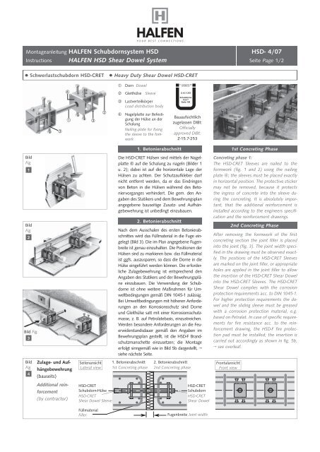
● Schwerlastschubdorn <strong>HSD</strong>-CRET ● Heavy Duty Shear Dowel <strong>HSD</strong>-CRET<br />
Bild<br />
Fig.<br />
1<br />
Bild<br />
Fig.<br />
2<br />
Bild Fig.<br />
3<br />
Bild<br />
Fig.<br />
4<br />
<br />
Zulage- und Aufhängebewehrung<br />
(bauseits)<br />
Additional reinforcement<br />
(by contractor)<br />
<br />
Seitenansicht<br />
Lateral view<br />
<strong>HSD</strong>-CRET<br />
Schubdorn-Hülse<br />
<strong>HSD</strong>-CRET<br />
Shear Dowel Sleeve<br />
Füllmaterial<br />
Filler<br />
<br />
Dorn Dowel<br />
Gleithülse Sleeve<br />
Lastverteilkörper<br />
Load distribution body<br />
Nagelplatte zur Befestigung<br />
der Hülse an der<br />
Schalung<br />
Nailing plate for fi xing<br />
the sleeve to the fomwork<br />
Die <strong>HSD</strong>-CRET Hülsen sind mittels der Nagelplatte<br />
auf die Schalung zu nageln (Bilder 1<br />
u. 2); dabei ist auf die horizontale Lage der<br />
Hülsen zu achten. Der Schutzaufkleber darf<br />
nicht entfernt werden, da er das Eindringen<br />
von Beton in die Hülsen während des Betoniervorganges<br />
verhindert. Die gem. den Angaben<br />
des Statikers und dem Bewehrungsplan<br />
angegebene bauseitige Zusatz- und Aufhängebewehrung<br />
ist unbedingt einzubauen.<br />
Nach dem Ausschalen des ersten Betonierabschnittes<br />
wird das Füllmaterial in die Fuge eingelegt<br />
(Bild 3). Die im Plan angegebene Fugenbreite<br />
ist genau einzuhalten. Die Positionen der<br />
Hülsen sind zu markieren bzw. das Füllmaterial<br />
ist ggfs. auszusparen, so dass die Dorne in die<br />
Hülse eingeführt werden können. Die erforderliche<br />
Zulagebewehrung ist entsprechend den<br />
Angaben des Statikers und der Bewehrungspläne<br />
einzubauen. Die Verwendung der Schubdorne<br />
ist ohne weitere Maßnahmen für Umweltbedingungen<br />
gemäß DIN 1045-1 zulässig.<br />
Bei Umweltbedingungen mit höheren Anforderungen<br />
an den Korrosionsschutz sind Dorne<br />
und Gleithülse satt mit einer Korrosionsschutzmasse,<br />
z. B. auf Petrolatebasis, einzustreichen.<br />
Werden besondere Anforderungen an die Feuerwiderstandsdauer<br />
gemäß den Angaben im<br />
Bewehrungsplan gestellt, ist die <strong>HSD</strong>-F Brandschutzmanschette<br />
einzusetzen; die Montage<br />
erfolgt sinngemäß wie in Bild 5b dargestellt, →<br />
siehe nächste Seite.<br />
1. Betonierabschnitt<br />
1st Concreting phase<br />
2. Betonierabschnitt<br />
253<br />
Bauaufsichtlich<br />
zugelassen DIBt:<br />
Officially<br />
approved DIBt:<br />
Z-15.7-253<br />
1. Betonierabschnitt 1st Concreting Phase<br />
2. Betonierabschnitt<br />
2nd Concreting phase<br />
<strong>HSD</strong>-CRET<br />
Schubdorn<br />
<strong>HSD</strong>-CRET<br />
Shear Dowel<br />
Fugenbreite Joint width<br />
Concreting phase 1:<br />
The <strong>HSD</strong>-CRET Sleeves are nailed to the<br />
formwork (fi g. 1 and 2) using the nailing<br />
plate ; the sleeves must be placed exactly<br />
in horizontal position. The protective sticker<br />
may not be removed, because it protects<br />
the ingress of concrete into the sleeve during<br />
the concreting. It is absolutely important,<br />
that the additional reinforcement is<br />
installed according to the engineers specifi -<br />
cation and the reinforcement drawings.<br />
2nd Concreting Phase<br />
After removing the formwork of the fi rst<br />
concreting section the joint fi ller is placed<br />
into the joint (fi g. 3). The joint width specifi<br />
ed in the drawing must be observed exactly.<br />
The positions of the <strong>HSD</strong>-CRET Sleeves<br />
are marked on the joint fi ller, or appropriate<br />
holes are applied in the joint fi ller to allow<br />
the insertion of the <strong>HSD</strong>-CRET Shear Dowel<br />
into the <strong>HSD</strong>-CRET Sleeves. The <strong>HSD</strong>-CRET<br />
Shear Dowel complies with the corrosion<br />
protection requirements acc. to DIN 1045-1.<br />
For higher protection requirements the dowel<br />
and the sliding sleeve must be greased<br />
with a corrosion protection material, e.g.<br />
based on Petralat. In case of specifi c requirements<br />
for fi re resistance acc. to the reinforcement<br />
drawing, the <strong>HSD</strong>-F fi re protection<br />
pad must be installed; the insertion is<br />
carried out accordingly as shown in fi g. 5b,<br />
→ see overleaf.<br />
Frontalansicht<br />
Front view
<strong>Montageanleitung</strong> <strong>HALFEN</strong> <strong>Schubdornsystem</strong> <strong>HSD</strong> <strong>HSD</strong>- 4/<strong>07</strong><br />
Instructions <strong>HALFEN</strong> <strong>HSD</strong> Shear Dowel System Seite Page 2/2<br />
● Einzelschubdorne <strong>HSD</strong> ● Single Shear Dowel <strong>HSD</strong><br />
1<br />
2<br />
3<br />
4<br />
5a<br />
5b<br />
Brandschutzmanschette <strong>HSD</strong>-F<br />
Fire protection pad <strong>HSD</strong>-F<br />
6<br />
Halfen GmbH<br />
Liebigstr. 14 ⋅ 4<strong>07</strong>64 Langenfeld ⋅ GERMANY<br />
+49 - (0)2173 / 970-9030<br />
+49 - (0)2173 / 970-420<br />
E-Mail: bewehrung@halfen.de<br />
www.halfen.com<br />
1. Betonierabschnitt 1st Concreting Phase<br />
1. 1 <strong>HSD</strong> Hülse an Schalung befestigen 1. 1 Fixing the <strong>HSD</strong> sleeve to the formwork<br />
<strong>HSD</strong> Hülse gemäß vorgesehener Position Nail the <strong>HSD</strong> Sleeve to the formwork at<br />
an die Schalung nageln. Wichtig: Die Hül- the specifi ed position. Important: the<br />
se muss exakt in Gleitrichtung ausgerich- sleeve must aligned exaclty in the directet<br />
sein.<br />
tion of sliding.<br />
HINWEIS: Aufkleber nicht entfernen.<br />
Dieser schützt die Hülse gegen das Eindringen<br />
von Frischbeton<br />
2. 2 Bewehrung<br />
Verlegen der bauseitigen Zulage- und Rückhängebewehrung<br />
sowie der Bauteilbewehrung.<br />
Betonieren des 1. Abschnitts.<br />
3. 3 Fugenmaterial<br />
Anbringen des Fugenmaterials.<br />
4. 4 Markierung der Hülsenpositionen<br />
Die Positionen der <strong>HSD</strong> Hülsen sind ggf.<br />
genau zu markieren.<br />
5. 5a Schubdorn<br />
Der zur <strong>HSD</strong> Hülse passende Schubdorn<br />
<strong>HSD</strong>-D ist nun durch das Fugenmaterial<br />
hindurch einzuführen und bis zum Anschlag<br />
(Sicherheitsstopfen) in die Hülse zu<br />
schieben.<br />
5b Schubdorn mit Brandschutzmanschette<br />
Bei Brandschutzanforderungen gem.<br />
DIN 4102 ist für die Brandschutzmanschette<br />
<strong>HSD</strong>-F eine Aussparung im Fugenmaterial<br />
vorzusehen. Die Brandschutzmanschette<br />
wird auf den Schubdorn aufgesteckt, wie<br />
dargestellt. Einsetzen des Schubdorns in die<br />
Gleithülse wie unter 5a beschrieben.<br />
6. 6 Bewehrung<br />
Verlegen der bauseitigen Zulage- und Rückhängebewehrung<br />
sowie der Bauteilbewehrung.<br />
Betonieren des 2. Abschnitts.<br />
NOTE: Do not remove the label. It is necessary<br />
to protect the sleeve against ingress<br />
of fresh concrete.<br />
2. 2 Reinforcement<br />
Install the reinforcement specifi ed additionally<br />
for the shear dowel (by contractor)<br />
and the reinforcement of the structure.<br />
Concreting of the 1st phase.<br />
2. Betonierabschnitt 2nd Concreting Phase<br />
3. 3 Joint fi ller<br />
Apply the joint fi lling material.<br />
4. 4 Marking the positions of the sleeves<br />
Mark the exact positions of the <strong>HSD</strong><br />
sleeves, if required.<br />
5 5a Shear dowel<br />
Insert the appropriate shear dowel<br />
<strong>HSD</strong>-D through the joint fi ller into the<br />
<strong>HSD</strong> sleeve until it comes to the stop (safety<br />
plug).<br />
5 5b Shear dowel with fi re protection pad<br />
If fi re protection acc. to DIN 4102 is<br />
required, a recess must be provided in<br />
the joint fi ller to accomodate the <strong>HSD</strong>-F<br />
fi re protection pad. The fi re protection<br />
pad is shifted on the shear dowel as<br />
shown in the drawing. Insert the shear<br />
dowel into the sleeve as described in 5a.<br />
6. 6 Reinforcement<br />
Install the reinforcement specifi ed additionally<br />
for the shear dowel (by contractor)<br />
and the reinforcement of the structure.<br />
Concreting of the 2nd phase.<br />
Das Qualitätsmanagementsystem von Halfen GmbH ist für die<br />
Standorte in Deutschland, in der Schweiz und in Polen zertifiziert<br />
nach DIN EN ISO 9001:2000, Zertifikat-Nr. QS-281 HH.<br />
The Quality Management System of Halfen GmbH is certified for<br />
the locations in Germany, Switzerland and Poland according to<br />
, Certificate No. QS-281 HH.<br />
U - 329 - 04/<strong>07</strong><br />
117