Montageanleitung - HZ Weitzel
Montageanleitung - HZ Weitzel
Montageanleitung - HZ Weitzel

Erfolgreiche ePaper selbst erstellen
Machen Sie aus Ihren PDF Publikationen ein blätterbares Flipbook mit unserer einzigartigen Google optimierten e-Paper Software.
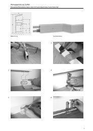
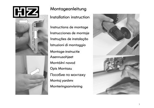
<strong>Montageanleitung</strong><br />
Installation instruction<br />
Instructions de montage<br />
Instrucciones de montaje<br />
Instruções de instalação<br />
Istruzioni di montaggio<br />
Montage-instructie<br />
Asennusohjeet<br />
Montážní navod<br />
Opis Montazu<br />
<br />
Montaj yardm yardimi<br />
Monteringsanvisning<br />
1
<strong>Montageanleitung</strong> SLF 2000: Das universelle Profil zur Rohrverkleidung bis 22 mm in acht Dekoren<br />
Installation instruction: SLF 2000 and Basics: The universal profile up to 22 mm in eight finishes<br />
1 2<br />
~0,5 m<br />
2
3 4<br />
Ø 8 mm<br />
3..5 mm<br />
5 6<br />
3
<strong>Montageanleitung</strong> SLF 2000: Das universelle Profil zur Rohrverkleidung bis 22 mm in acht Dekoren<br />
Installation instruction: SLF 2000 and Basics: The universal profile up to 22 mm in eight finishes<br />
7 8<br />
9 10<br />
0,5 m<br />
1<br />
2<br />
4
11 12<br />
Ø 8 mm<br />
3..5 mm<br />
13 14<br />
5
<strong>Montageanleitung</strong> SLF 2000: Das universelle Profil zur Rohrverkleidung bis 22 mm in acht Dekoren<br />
Installation instruction: SLF 2000 and Basics: The universal profile up to 22 mm in eight finishes<br />
15 16<br />
1<br />
2<br />
17 18<br />
1<br />
2<br />
3<br />
3..5 mm<br />
6
19 20<br />
2<br />
1<br />
21 22<br />
Ø 8 mm<br />
- 45 mm<br />
7
<strong>Montageanleitung</strong> SLF 2000: Das universelle Profil zur Rohrverkleidung bis 22 mm in acht Dekoren<br />
Installation instruction: SLF 2000 and Basics: The universal profile up to 22 mm in eight finishes<br />
23 24<br />
25 26<br />
Ø 8 mm<br />
8
27 90° +/- 10°<br />
28<br />
29 30<br />
90° +/- 10°<br />
+/- 10°<br />
9
<strong>Montageanleitung</strong> SLF 2000: Das universelle Profil zur Rohrverkleidung bis 22 mm in acht Dekoren<br />
Installation instruction: SLF 2000 and Basics: The universal profile up to 22 mm in eight finishes<br />
31 32<br />
33 34<br />
10
35 36<br />
37 38<br />
45°<br />
11
<strong>Montageanleitung</strong> SLF 2000: Das universelle Profil zur Rohrverkleidung bis 22 mm in acht Dekoren<br />
Installation instruction: SLF 2000 and Basics: The universal profile up to 22 mm in eight finishes<br />
39 40<br />
41 42<br />
12
A B<br />
Schelle Art. 2250 Bracket art. no. 2250 Schelle Art. 2150 Bracket art. no. 2150<br />
Die Schelle Art.-Nr. 2250 ist besonders bei unebenen Wänden, weichem oder schadhaftem Putz geeignet. Der empfohlene<br />
Schellenabstand beträgt 50 cm. Bei den Ecken besteht die Wahlmöglichkeit zwischen Eckschellen mit Formteil (ohne<br />
Gehrungsschnitt) und Ecken für Sonderlösungen (mit Gehrungsschnitt). Bei Verwendung der Inneneckschelle mit Inneneck-<br />
formteil sind für jedes zuzuschneidende Profil 45 mm in der Länge abzuziehen.<br />
Bracket art. no. 2250 is particularly well suited for uneven walls, damaged or soft plaster. We recommend spacing the brackets every 50 cm.<br />
When using the inner corner you need an inner corner bracket, when using the outer corner an outer corner bracket is needed.<br />
When cutting the skirting board profile to size, remember that for each inner corner bracket used the profile has to be shortened by 45 mm.<br />
For working without inner or outer corner brackets use inner or outer corner for custom solutions and mitre cuts are needed.<br />
Falls eine spannungsfreie Rohrausdehnung nicht möglich ist, sind Ausgleichsbögen oder handelsübliche Kompensatoren einzubauen!<br />
If expansion of the pipes without stress is not possible, standard commercial expansion joints should be used.<br />
13
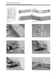
<strong>Montageanleitung</strong> SLT 2000: Profil zur Rohrverkleidung bis 22 mm mit Selbstklebeband für Teppichboden<br />
Installation instruction SLT 2000: Profile with self-adhesive tape for laying carpets, for pipes up to 22 mm<br />
Folgen Sie zunächst der Basisanleitung SLF 2000,<br />
At first follow basic instruction SLF 2000,<br />
Bild 1 bis 22 und Bild 26 bis 30<br />
picture 1 - 22 and picture 26 -30<br />
43<br />
- 45 mm<br />
44<br />
14
45 46<br />
47 48<br />
Das Selbstklebeband ist nur für Teppichböden mit glatter Schaumbeschichtung geeignet. Bei sonstigen Teppichböden<br />
ist zusätzlich ein Kontaktkleber oder ein Doppelklebeband erforderlich.<br />
The self-adhesive tape is only suitable for carpets with a smooth foam coating. With other carpeting additional<br />
contact adhesive or additional double-sided adhesive tape is necessary.<br />
15
<strong>Montageanleitung</strong> SLL 2000: Profil für Einsatz eines Kabelkanals oder eines dritten Rohres bis 22 mm<br />
Installation instruction SLL 2000: The profile for inserting a cable duct or a 3rd pipe up to 22 mm<br />
Folgen Sie zunächst der Basisanleitung SLF 2000,<br />
Bild 1 bis 22 und Bild 26 bis 30 unter Beachtung der<br />
nachfolgenden Schritte<br />
49 50<br />
30 mm x<br />
30 mm<br />
At first follow basic instruction SLF 2000,<br />
picture 1 - 22 and picture 26 - 30 under<br />
consideration of following steps<br />
Ø 8 mm<br />
16
51 52<br />
30 mm x<br />
30 mm<br />
53 54<br />
Ø 8 mm<br />
3..5 mm<br />
Ø 8 mm<br />
1<br />
2<br />
Ø 6 mm<br />
17
<strong>Montageanleitung</strong> SLL 2000: Profil für Einsatz eines Kabelkanals oder eines dritten Rohres bis 22 mm<br />
Installation instruction SLL 2000: The profile for inserting a cable duct or a 3rd pipe up to 22 mm<br />
55 56<br />
Obere Rohrleitung ist immer Vorlauf, untere Rohrleitung ist immer Rücklauf. Die Schelle Art.-Nr. 2250 ist besonders bei unebenen<br />
Wänden, weichem oder schadhaftem Putz geeignet. Der empfohlene Schellenabstand beträgt 50 cm. In den Ecken besteht die<br />
Wahlmöglichkeit zwischen Eckschellen mit Formteil (ohne Gehrungsschnitt) und Ecken für Sonderlösungen (mit Gehrungsschnitt).<br />
Bei Verwendung der Inneneckschelle mit Inneneckformteil sind für jedes zuzuschneidende Profil 45 mm in der Länge abzuziehen.<br />
Bracket art. no. 2250 is particularly well suited for uneven walls, damaged or soft plaster. We recommend spacing the brackets<br />
every 50 cm. When using the inner corner you need an inner corner bracket, when using the outer corner an outer corner bracket<br />
is needed. When cutting the skirting board profile to size, remember that for each inner corner bracket used the profile has to be<br />
shortened by 45 mm. For working without inner or outer corner brackets use inner or outer corner for custom solutions and mitre<br />
cuts are needed.<br />
1<br />
2<br />
18
Der Prüfbericht der Informationsprüfung des VDE- Institutes vom 21.06.1996, Az: 19692-8100-4001-A3D, kann bei der<br />
Hans <strong>Weitzel</strong> GmbH & Co. KG eingesehen werden. Die Verwendung eines Kabelkanals (z.B. 30 x 30 mm) ist grundsätzlich<br />
vorzusehen, wobei dieser unter der Rücklaufleitung zu platzieren ist. Bei Vorlauftemperaturen von über 70 °C oder<br />
abweichenden Betriebsbedingungen setzten Sie sich bitte mit uns in Verbindung!<br />
The test report from the informative inspection by the VDE institute dated 21.06.96, ref. 19692-8100-4001-A3D, is available from<br />
Hans <strong>Weitzel</strong> GmbH & Co. KG. Rules for installation:<br />
Forward flow - always upper pipe, backflow - always lower pipe. Cable ducts from 30 x 30 mm, use those with VDE approv.<br />
symbol (e.g. Tehalit LF 30030), have to be placed under the backflow pipe.<br />
C D<br />
19
Passende Referenzfabrikate zur Montage in den <strong>HZ</strong>-Steckdosencontainer:<br />
GIRA<br />
Giersiepen GmbH & Co.KG<br />
Dahlienstr.<br />
D- 42477 Radevormwald<br />
weitere Hersteller für<br />
Geräteeinsätze:<br />
Busch-Jaeger Elektro GmbH<br />
Freisenbergstr. 2<br />
D- 58513 Lüdenscheid<br />
Albrecht Jung GmbH & Co.KG<br />
Volmestr. 1<br />
D- 58579 Schalksmühle<br />
Berker GmbH & Co.KG<br />
PSF. 1160<br />
D- 58567 Schalksmühle<br />
Merten GmbH & Co.KG<br />
PSF. 100653<br />
D- 51606 Gummersbach<br />
20
<strong>Montageanleitung</strong> SLF 28- 2000: Profil zur Rohrverkleidung bis 28 mm und größerem Platzbedarf<br />
Installation instruction SLF 28- 2000: The profile for pipes up to 28 mm and when more space is needed<br />
57 58<br />
~0,5 m<br />
Ø 8 mm<br />
3..5 mm<br />
21
<strong>Montageanleitung</strong> SLF 28- 2000: Profil zur Rohrverkleidung bis 28 mm und größerem Platzbedarf<br />
Installation instruction SLF 28- 2000: The profile for pipes up to 28 mm and when more space is needed<br />
59 60<br />
Folgen Sie dann weiter der Basisanleitung SLF 2000,<br />
Bild 33 bis Bild 42<br />
Please follow with basic instruction SLF 2000,<br />
picture 33 to 42<br />
Der empfohlene Schellenabstand beträgt 50 cm.<br />
In den Ecken erfolgt ein Gehrungsschnitt (45°) und Verwendung der Innen- bzw. Außenecke als Formteil.<br />
We recommend spacing the brackets every 50 cm. Profile SLF 28 is only working without inner or outer<br />
corner brackets. Please use inner or outer corner for custom solutions and mitre cuts.<br />
Grundsätzlicher Hinweis bei der Rohrverlegung:<br />
Falls eine spannungsfreie Rohrausdehnung nicht möglich ist, sind Ausgleichsbögen (Lyrabogen bzw.<br />
Richtungswechsel) oder handelsübliche Kompensatoren einzubauen!<br />
If expansion of the pipes without stress is not possible, standard commercial expansion joints should be<br />
used.<br />
22
<strong>Montageanleitung</strong> SLHW: Holzwerkstoffsockelleiste, Natur oder mit Funier Abachi bzw. Funier Eiche hell<br />
Installation instruction SLHW: Skirting board of wood-based material<br />
61 62<br />
23
<strong>Montageanleitung</strong> SLHW: Holzwerkstoffsockelleiste, Natur oder mit Funier Abachi bzw. Funier Eiche hell<br />
Installation instruction SLHW: Skirting board of wood-based material<br />
63 64<br />
50 mm<br />
65 66<br />
24
67 68<br />
69 70<br />
~130 mm<br />
~130 mm<br />
25
<strong>Montageanleitung</strong> SLHW: Holzwerkstoffsockelleiste, Natur oder mit Funier Abachi bzw. Funier Eiche hell<br />
Installation instruction SLHW: Skirting board of wood-based material<br />
71 72<br />
73 74<br />
Ø 8 mm<br />
45 mm<br />
45°<br />
26
75 76<br />
Ø 8 mm<br />
77 78<br />
27
<strong>Montageanleitung</strong> SLHW: Holzwerkstoffsockelleiste, alternative Befestigung mit Linsenschrauben<br />
Installation instruction SLHW: Skirting board of wood-based material - alternativ of plugging<br />
79 80<br />
81 82<br />
45°<br />
28
83<br />
Grundsätzlicher Hinweis bei der Rohrverlegung:<br />
Falls eine spannungsfreie Rohrausdehnung nicht möglich ist, sind Ausgleichsbögen (Lyrabogen bzw.<br />
Richtungswechsel) oder handelsübliche Kompensatoren einzubauen!<br />
If expansion of the pipes without stress is not possible, standard commercial expansion joints should<br />
be used.<br />
29
<strong>Montageanleitung</strong> BLF: Blindleistenprofile aus Kunststoffhohlkammerprofil<br />
Installation instruction BLF: Dummy skirting board profiles of plastic hollow space profile<br />
84 85<br />
~0,5 m<br />
~0,5 m<br />
Ø 6 mm<br />
32
86 87<br />
1<br />
88 89<br />
2<br />
BLF - SLF<br />
rechts<br />
right<br />
BLF - BLF<br />
BLF - SLF<br />
links<br />
left<br />
33
<strong>Montageanleitung</strong> BLF: Blindleistenprofile aus Kunststoffhohlkammerprofil<br />
Installation instruction BLF: Dummy skirting board profiles of plastic hollow space profile<br />
90 91<br />
45°<br />
Blindleistenhalter sind alle 50 cm zu setzen. Die Formteile (Innenecke, Außenecke, Stoßverbinder, Endstück)<br />
sind an ihrer Unterseite mit einer Sollbruchstelle versehen. Wir empfehlen, das Formteil mit einem Teppichmesser<br />
(Cutter) zu kürzen; bewährt hat sich auch der Einsatz einer Mini-Schwingsäge.<br />
Durch vollständiges Einkürzen (z.B. Bild 87) können die Formteile zur Verbindung zweier Blindleisten verwendet<br />
werden. Durch einseitiges Kürzen (z.B. Bild 88 und Bild 89) kann mit den Formteilen ein Übergang<br />
zwischen Blindleiste und rohrführender Sockelleiste hergestellt werden.<br />
Dummy skirting board holders should be spaced every 50 cm. The moulded parts for the SLF profile<br />
illustrated below have a predetermined breaking point on the backside. This means they can be used both as<br />
mouldet parts for dummy skirting boards and also for transition from skirting board to dummy skirting board.<br />
We recommend cutting the breaking points off with a carpet knife or scissors.<br />
34
BLT Blindleistenprofil mit Teppicheinsatz und BL Blindleiste aus Massivholz<br />
BLT Dummy skirting board for carpets and BL dummy skirting board made of solid wood<br />
Blindleistenprofil mit Teppicheinsatz / Dummy skirting board for carpets:<br />
Die Blindleisten werden alle 50…70 cm mit dem Nageldübel Art. 204 befestigt, wobei der Schraubenkopf durch den<br />
aufgeklebten Teppichboden verdeckt wird. In den Ecken wird auf Gehrung gearbeitet. Das Selbstklebeband ist nur<br />
für Teppichböden mit glatter Schaumbeschichtung geeignet. Ansonsten verwenden Sie zusätzlichen Kontaktkleber.<br />
The dummy skirting boards are mounted with the nail plug art. no. 204 in space every 50 cm. The screw head is<br />
covered by the carpet once it is stuck down. Dummy skirting board holders are unnecessary. Precise mitre cuts are<br />
needed in the corners. The self-adhesive tape is only suitable for carpets with a smooth foam coating with other<br />
carpeting additional contact adhesive or additional double-sided adhesive tape is necessary.<br />
Blindleiste aus Massivholz / Dummy skirting board made of solid wood:<br />
Die Befestigung sollte mit Messinglinsenkopf- oder Edelstahlschrauben und entsprechenden Dübeln (bauseits)<br />
erfolgen. Ein deckender Anstrich (nach vorherigem Grundieren) oder eine Oberflächenbehandlung (mit Wachs,<br />
Beize, Lasur, Klarlack oder Parkettversiegelung) ist nötig. In den Ecken wird auf Gehrung gearbeitet.<br />
To obtain a better appearance a brass cheese head screw and wall plug should be used for mounting. Precise mitre<br />
cuts are needed in the corners. The HW-skirting boards with a veneer are for staining, for varnishing or applying<br />
an opaque coat of paint.<br />
35
<strong>Montageanleitung</strong> Heizkörperanschlüsse HKU ohne Springbogen: Löten 15/ 18/ 22 mm, Pressen 15/ 18 mm, Schrauben<br />
Installation instruction radiator connections HKU: For soldering 15/ 18/ 22 mm, pressfitting 15/ 18 mm or screw elements<br />
92 93<br />
50 mm<br />
36
94 95<br />
96 97<br />
A<br />
A<br />
B<br />
37
<strong>Montageanleitung</strong> Heizkörperanschlüsse HKU ohne Springbogen: Löten 15/ 18/ 22 mm, Pressen 15/ 18 mm, Schrauben<br />
Installation instruction radiator connections HKU: For soldering 15/ 18/ 22 mm, pressfitting 15/ 18 mm or screw elements<br />
98 99<br />
B<br />
100 101<br />
38
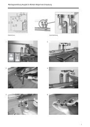
102 103<br />
104 105<br />
Einstellung der Durchflussmenge siehe Bild "L", S. 46<br />
Adjustment of flow rate at picture "L" , page 46<br />
+ zu<br />
zu<br />
close<br />
close<br />
39
<strong>Montageanleitung</strong> Heizkörperanschlüsse HKU ohne Springbogen: Löten 15/ 18/ 22 mm, Pressen 15/ 18 mm, Schrauben<br />
Installation instruction radiator connections HKU: For soldering 15/ 18/ 22 mm, pressfitting 15/ 18 mm or screw elements<br />
106 107<br />
zu<br />
close<br />
H 2O<br />
108 109<br />
40
110 111<br />
E<br />
T max = 90 °C<br />
p max = 5 bar<br />
41
F<br />
G<br />
<strong>Montageanleitung</strong> Heizkörperanschlüsse HKU - Übersicht der Heizkörperanschlüsse<br />
Installation instruction: General summery of radiator connections HKU<br />
HKU, zweiteilig,<br />
zum Löten.<br />
HKU, two-piece,<br />
for soldering.<br />
HKU, zweiteilig,<br />
zum Löten.<br />
HKU, two-piece,<br />
for soldering.<br />
Im Falle des Hartlötens empfehlen wir Degussa Braze Tec<br />
Flussmittel Braze Tec Hartlot 4576<br />
For braze joints we recommend Braze Tec Flussmittel<br />
Degussa h and Braze Tec Hartlot Degussa 4576.<br />
Im Falle des Hartlötens empfehlen wir Degussa Braze Tec<br />
Flussmittel Braze Tec Hartlot 4576<br />
For braze joints we recommend Braze Tec Flussmittel<br />
Degussa h and Braze Tec Hartlot Degussa 4576.<br />
42
H<br />
I<br />
K<br />
HKU, zweiteilig,<br />
zum Kupferpressen,<br />
für Viega "profipress".<br />
HKU, two-piece,<br />
for copper press-fitting,<br />
for Viega "profipress".<br />
HKU, zweiteilig,<br />
zum Kupferpressen,<br />
für Mapress System.<br />
HKU, two-piece,<br />
for copper press-fitting,<br />
for Mapress System.<br />
HKU, zweiteilig,<br />
zum Kupferpressen,<br />
für Viega "profipress"<br />
HKU, two-piece,<br />
for copper press-fitting,<br />
for Viega "profipress"<br />
43
L<br />
M<br />
<strong>Montageanleitung</strong> Heizkörperanschlüsse HKU - Übersicht der Heizkörperanschlüsse<br />
Installation instruction: General summery of radiator connections HKU<br />
HKU, zweiteilig,<br />
mit 1/2" Innengewinde.<br />
HKU, two-piece,<br />
with 1/2" female thread.<br />
HKU, zweiteilig,<br />
mit 3/4" Eurokonus.<br />
HKU, two-piece,<br />
with 3/4" male thread<br />
and tapered seal<br />
(Eurokonus).<br />
Die passende Übergangsverschraubung auf 1/2" Innengewinde<br />
erfragen Sie bei Ihrem Verbundrohrhersteller.<br />
The pipe is connected with an adaptor union fitting the<br />
12” female thread / tapered seal from the relevant pipe<br />
manufacturer.<br />
Die passende Übergangsverschraubung auf 3/4" AG<br />
Eurokonus erfragen Sie bei Ihrem Verbundrohrhersteller.<br />
The pipe is connected with an adaptor union fitting the<br />
34” male thread / tapered seal from the relevant pipe<br />
manufacturer.<br />
44
<strong>HZ</strong>-Heizkörperanschlüsse und Ausgleichs-Winkel-<br />
Absperrverschraubungen sind für einen Betriebsüberdruck<br />
von maximal 5 bar und eine Dauerbetriebstemperatur von<br />
maximal 90 °C geeignet. Für beabsichtigte<br />
Betriebsbedingungen über diesen maximalen Werten<br />
kontaktieren Sie uns bitte.<br />
Obere Rohrleitung ist immer Vorlauf, untere Rohrleitung ist<br />
immer Rücklauf. Die Anschlüsse sind für rechten, linken oder<br />
mittigen Anschluss am Heizkörper einsetzbar.<br />
Falls eine spannungsfreie Rohrausdehnung nicht möglich<br />
ist, sind Ausgleichsbögen bzw. handelsübliche<br />
Kompensatoren einzubauen!<br />
Für alle von <strong>HZ</strong> gelieferten Klemmring- Verschraubungen<br />
gilt immer: Überwurfmutter handfest anziehen und mit<br />
einem Schraubenschlüssel maximal eine Umdrehung<br />
nachziehen!<br />
Bei Verwendung der <strong>HZ</strong>- Profile müssen folgende<br />
Mindestabstände zwischen dem Anschlußgewinde des<br />
Heizkörpers und der Oberkante des Fertigfußbodens<br />
berücksichtigt werden:<br />
Profile SLF, SLT und SLHW:<br />
Profil SLF 28<br />
Profil SLL<br />
mindestens 165 mm<br />
mindestens 180 mm<br />
mindestens 190 mm<br />
Für den Anschluß der Ausgleichs-Winkel-Absperrverschraubung<br />
sind nur die von <strong>HZ</strong> gelieferten<br />
Klemmringverschraubungen oder gleichwertige metallisch<br />
dichtende Verschraubungen zugelassen.<br />
<strong>HZ</strong> radiator connections and 90° elbows with shut-off<br />
valve are designed for a maximal positive operating<br />
pressure of 5 bar and a maximal permanent operating<br />
temperature of 90°C. Please contact us if your planned<br />
operating conditions exceed these maximal values.<br />
The upper pipe is the forward flow. The lower pipe is the<br />
backflow. It can be used both for the right, the left and<br />
the middle-hand radiator connection.<br />
If expansion of the pipes without stress is not possible,<br />
standard commercial expansion joints should be used.<br />
The following applies to all <strong>HZ</strong> compression joints:<br />
tighten the union nut as far as possible by hand and then<br />
turn max. once with a spanner.<br />
When using the <strong>HZ</strong> skirting board profiles the following<br />
minimum clearances must be observed between the<br />
connection thread of the radiator and the finished floor<br />
level:<br />
Profile SLF, SLT and SLHW:<br />
Profil SLF 28<br />
Profil SLL<br />
at least 165 mm<br />
at least 180 mm<br />
at least 190 mm<br />
Only the compression fittings supplied by <strong>HZ</strong> or<br />
equivalent metal-to-metal sealing fittings must be used to<br />
connect the 90° elbow with shut-off valve.<br />
45
N<br />
O<br />
<strong>Montageanleitung</strong> Ausgleichs-Winkel-Absperrverschraubung AWA und Passbogenverschraubung PB<br />
Installation instruction AWA: 90° elbow with shut-off valve and 90° bend PB<br />
Einstellung der Durchflussmenge für Ausgleichs-Winkel-Absperrverschraubung, Art.-Nr. 1022, 1023L<br />
Adjustment of flow rate for art. no. 1022, 1023L<br />
NEU BEI <strong>HZ</strong>:<br />
AWA- Montagelehre<br />
zum schnellen und einfachen Einmessen<br />
zwischen <strong>HZ</strong> Heizkörperanschluss und<br />
Heizkörper<br />
46
P<br />
R<br />
voreinstellbar<br />
absperrbar 15 mm Kupferrohr, verchromt,<br />
Tiefe: 125 mm passend zu allen <strong>HZ</strong>- Heizkörperanschlüssen.<br />
Höhe: 100 mm Höhe und Tiefe durch Ablängen frei wählbar,<br />
integrated valve inkl. Klemmringverschraubung zum Heizkörpercan<br />
be shut off<br />
Length: 125 mm<br />
anschluss.<br />
AWA Art. 1022 Height: 100 mm 15 mm precision steel tube, chromium plated,<br />
fits with all <strong>HZ</strong> radiator connections.<br />
Can be trimmed to required height and depth,<br />
incl. compression joint to the radiator connector<br />
voreinstellbar<br />
absperrbar<br />
Entleerungsfunktion<br />
Tiefe: 150 mm<br />
Höhe: 100 mm<br />
integrated valve<br />
can be drained<br />
AWA Art. 1023L Length: 150 mm<br />
Height: 100 mm<br />
Für alle Ausgleichs-Winkel-Absperrverschraubungen<br />
und Passbogenverschraubungen:<br />
For all 90° elbow with shut-off valve and 90° bend:<br />
Klemmringverschraubung zum Anschluß am<br />
Heizkörper mit KVI Art.: 1026 (1/2" Innengewinde<br />
am Heizkörper) oder KVA Art. 1025<br />
(3/4" Außengewinde am Heizkörper)<br />
Compression joint between 90° bend and the<br />
radiator art. no. 1026 (with self-sealing double<br />
nipple with 12” female thread) or art. no. 1025<br />
(with self-sealing 3/4” male thread)<br />
47
S<br />
T<br />
<strong>Montageanleitung</strong> Ausgleichs-Winkel-Absperrung AWA und Passbogenverschraubung PB: Übersicht<br />
Installation instruction: General summery of 90° elbow with shut-off valve and 90° bend PB<br />
Vorlaufbogen:<br />
Tiefe: 120 mm<br />
Höhe: 1000 mm<br />
Rücklaufbogen:<br />
Tiefe: 120 mm<br />
Höhe: 72 mm<br />
Forward flow:<br />
Length: 120 mm<br />
PBV- L Art. 1031 Height:1000 mm<br />
Backflow:<br />
Length: 20 mm<br />
Height: 72 mm<br />
PBV Art. 1021<br />
Tiefe: 120 mm<br />
Höhe: 72 mm<br />
Length: 120 mm<br />
Height: 72 mm<br />
Für seitlichen oben liegenden Anschluss am<br />
Heizkörper geeignet<br />
Suitable for side-top connection to the radiator<br />
Vorlauf mit Thermostatkopf und Rücklauf muss<br />
in Axialform oder Winkelform mit Klemmring für<br />
ø 15 mm sein<br />
forward flow with thermostat head and backflow<br />
must be valve in axial or angular form with<br />
locking ring for 15 mm Ø<br />
Passbogenverschraubung 1031 in Verbindung mit<br />
zweiteiligen, flachen Heizörperanschlüssen (Art.<br />
14XX) kann bei Verbundrohr bis 20 mm ø, bei<br />
Kupferrohr bis 18 mm ø verwendet werden<br />
90° bend 1031 for fitting two-piece flat radiator<br />
connections (art. no. 14XX) can only be used with<br />
composite pipes up to 20 mm Ø or with copper<br />
pipes up to 18 mm Ø<br />
48
U<br />
V<br />
<strong>Montageanleitung</strong> Heizkörperanschlüsse HKU : Unterputzanschluss, universell<br />
Installation instruction radiator connections HKU: In-wall connection, universal<br />
49
<strong>Montageanleitung</strong> Heizkörperanschlüsse HKU : Unterputzanschluss, universell<br />
Installation instruction radiator connections HKU: In-wall connection, universal<br />
112 113<br />
114<br />
50
W<br />
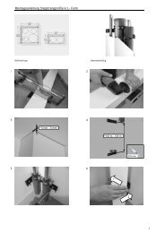
<strong>Montageanleitung</strong> STP-U: Steigstrangprofile in U-Form<br />
Installation instruction STP-U: Riser section, U-shaped<br />
STP-U, STP-L<br />
115 116<br />
51
<strong>Montageanleitung</strong> STP-U: Steigstrangprofile in U-Form<br />
Installation instruction STP-U and Basics: Riser section, U-shaped<br />
117 118<br />
119 120<br />
1<br />
~3 mm…5 mm<br />
2<br />
~0,6 m…0,8 m<br />
Ø 6 mm<br />
52
121 122<br />
123<br />
<strong>HZ</strong> Abhebewerzeug, Art. Nr. 9151 (AW)<br />
<strong>HZ</strong> lifting tool art. no. 9151 (AW)<br />
Befestigt werden die Steigstrangprofile mit den<br />
dazu gehörenden Befestigungsklammern in einem<br />
Abstand von ca. 0,6 m…0,8 m. Zur Befestigung<br />
eignet sich der Nageldübel Art. Nr. 204 (6 mm).<br />
The riser sections are mounted with matching<br />
mounting brackets, which are spaced approx. every<br />
0,6 m…0,8 m. Nail plugs, art. no. 204, are used to<br />
attach the brackets.<br />
Ø 6 mm<br />
53
X<br />
<strong>Montageanleitung</strong> STP-U: Steigstrangprofile in U-Form<br />
Installation instruction STP-U and Basics: Riser section, U-shaped<br />
Art. 780<br />
Art. 880<br />
Art. 980<br />
Art. 6580<br />
Bei Verlegung der Steigstrangprofile an der Decke<br />
muss aus Sicherheitsgründen das Profil zusätzlich<br />
mit Schrauben/ Dübeln befestigt werden.<br />
When laying riser sections on the ceiling, it is<br />
essential that wall plugs and screws are also used to<br />
attach the section as a safety measure.<br />
Die Steigstrangprofile sind tapezierbar und<br />
streichfähig (Acryl- und Latexfarben). Hierzu ist<br />
vorher das Profil mit Schleifvlies leicht anzurauhen.<br />
The riser sections can be wallpapered and painted<br />
(acrylic and latex paint). Slightly roughen the<br />
section surface with abrasive fabric before applying<br />
wallpaper or paint.<br />
Aufgrund der UV-Stabilität ist auch eine<br />
Außenanwendung der Steigstrangprofile möglich<br />
(z.B. Verkleidung von Solarleitungen). Es ist jedoch<br />
notwendig, das Hohlkammerprofil vor<br />
eindringender Nässe zu schützen (z.B. Verwendung<br />
von Enddeckeln).<br />
Their UV stability also allows outdoor installation<br />
of the riser sections (e.g. casing of solar lines).<br />
However, it is necessary to protect the hollow<br />
chamber profile against moisture penetration (e.g.<br />
use of end caps).<br />
54
<strong>Montageanleitung</strong> STP-L: Steigstrangprofile in L-Form<br />
Installation instruction STP-L: Riser section, L-shaped<br />
Folgen Sie zunächst der Basisanleitung STP-U,<br />
Bild 115 bis 123 unter Beachtung der Hinweise<br />
auf Seite 53.<br />
At first follow basic instruction STP-U picture<br />
115-123 unter consideration of remarks on<br />
page 53<br />
124<br />
125 126<br />
1<br />
2<br />
55
Y<br />
<strong>Montageanleitung</strong> STP-L: Steigstrangprofile in L-Form<br />
Installation instruction STP- L: Riser section, L-shaped<br />
Art. 6280<br />
Art. 6380<br />
Art. 6480<br />
Befestigt werden die Steigstrangprofile mit den<br />
dazu gehörenden Befestigungsklammern in einem<br />
Abstand von ca. 0,6 m…0,8 m. Zur Befestigung<br />
eignet sich der Nageldübel Art. Nr. 204 (6 mm).<br />
The riser sections are mounted with matching<br />
mounting brackets, which are spaced approx. every<br />
0,6 m …0,8 m. Nail plugs, art. no. 204, are used to<br />
attach the brackets.<br />
Für die Montage des Steigstrangprofiles Art. Nr.<br />
6480 werden werden 4 Befestigungklammern pro<br />
Meter benötigt (Abstand der Befestigungspunkte<br />
ca. 0,5 m).<br />
Four mounting brackets art. no. 989 are<br />
required per metre to install the riser<br />
section art. no. 6480.<br />
56
<strong>Montageanleitung</strong> STP: Zubehör<br />
Installation instruction STP: Accessories for riser sections<br />
weiche Dichtlippe, weiß, RAL 9010,<br />
zum Abdichten zur Wand hin,<br />
selbstklebend, 3 m- Längen,<br />
Art.-Nr. 6088<br />
Stoßabdeckprofil, weiß, RAL 9010,<br />
selbstklebend, Länge: 1m, zum Abdecken<br />
zweier Stöße, Art.-Nr. 6078<br />
Flexible sealing lip, white, RAL 9010,<br />
for sealing the STP on the wall, selfadhesive,<br />
length: 3 m, art. no. 6088<br />
Butt joint cover section, white, RAL 9010,<br />
for all riser sections, self-adhesive,<br />
length: 1 m, art. no. 6078<br />
Steigstrangrosette, weiß, RAL 9010,<br />
Riser rosette, white, RAL 9010,<br />
für seitlichen Rohraustritt:<br />
for pipe outlets at the side of riser sections:<br />
ø 15 mm/ ø 18 mm Art.-Nr. 6081 ø 15 mm/ ø 18 mm art.no. 6081<br />
ø 22 mm Art.-Nr. 6082 ø 22 mm<br />
art.no. 6082<br />
Enddeckel weiß, RAL 9010:<br />
<strong>HZ</strong> plastic end cover, white, RAL 9010:<br />
für STP 50 x 100 Art.-Nr. 784 for STP 50 x 100 art.no. 784<br />
für STP 75 x 150 Art.-Nr. 884 for STP 75 x 150 art.no. 884<br />
für STP 100 x 200 Art.-Nr. 984 for STP 100 x 200 art.no. 984<br />
Revisionstür, aus Stahlblech, Inspection door, white, RAL 9010,<br />
weiß, RAL 9010:<br />
sheet steel, for installing in STP:<br />
15 cm x 15 cm Art.-Nr. 6018 15 cm x 15 cm art.no. 6018<br />
15 cm x 20 cm Art.-Nr. 6028 15 cm x 20 cm art.no. 6028<br />
15 cm x 25 cm Art.-Nr. 6038 15 cm x 25 cm art.no. 6038<br />
57
Zubehör für Sockelleisten, Heizkörperanschlüsse und Steigstrangprofile<br />
Accessories for skirting boards, radiator connections and riser sections<br />
127 128<br />
Gehrungsschneidlade, Art. Nr. 146<br />
Mitre cutting device, art. no. 146<br />
129 130<br />
Abdeckblende für HKU, Art.Nr. 1310…1390<br />
Cover strip for radiator connection, art. no. 1310...1390<br />
Ausklinkzange Art. Nr. 9150<br />
Notching pliers to make recesses in skirting boards<br />
for the <strong>HZ</strong> radiator connection, art. no. 9150<br />
58
Notizen<br />
Notes<br />
59
Materialliste<br />
List of materials<br />
Nr.<br />
no.<br />
St./ m<br />
pc./ m<br />
Art. Nr.<br />
art no.<br />
Bezeichnung<br />
Description<br />
Größe/ Farbe<br />
Size/ Colour<br />
Notiz<br />
Note<br />
60
Materialliste<br />
List of materials<br />
Nr.<br />
no.<br />
St./ m<br />
pc./ m<br />
Art. Nr.<br />
art no.<br />
Bezeichnung<br />
Description<br />
Größe/ Farbe<br />
Size/ Colour<br />
Notiz<br />
Note<br />
61
Notizen<br />
Notes<br />
Es gelten die Vorschriften der AGB, des HGB und Preise des jeweiligen Fach- oder Großhandels. Stand der Technik: September 2010. Die Beschreibungen und Darstellungen erheben keinen<br />
Anspruch auf Vollständigkeit. Die hier und in unseren gesamten Unterlagen enthaltenen Angaben - einschließlich der Abbildungen - entsprechen dem aktuellen Stand unserer Kenntnisse und<br />
sind nach bestem Wissen richtig und zuverlässig. Sie stellen jedoch keine verbindliche Eigenschaftszusicherung dar. Eine solche Zusicherung erfolgt nur über unsere Erzeugnisnormen. Der<br />
Anwender dieser Erzeugnisse muss in eigener Verantwortung über dessen Eignung für den vorgesehenen Einsatz sorgfältig prüfen, erproben und entscheiden. Unsere Haftung richtet sich<br />
ausschließlich nach unseren Liefer - und Zahlungsbedingungen. Konstruktive und technische Aenderungen behalten wir uns im Zuge der Weiterentwicklung und Verbesserung ohne<br />
Vorankündigung vor, insofern die Einhaltung zutreffender Spezifikationen nicht beeinträchtigt wird. Für Profile gelten, soweit in vereinbarten DIN-Normen, Werksnormen und sonst nicht<br />
anders angegeben, folgende Toleranzen als vereinbart: soweit messbar, DIN 16941-3A sehr grob. Eine Garantie für Farbgleichheit und Farbbeständigkeit kann bei Artikeln aus polymeren<br />
Werkstoffen, sofern nicht ausdrücklich vereinbart, nicht übernommen werden. Bitte beachten Sie, dass wir keine Gewährleistung übernehmen können, wenn unsere Einbau-, Betriebs- oder<br />
Wartungsanleitungen nicht befolgt werden, die Produkte anderweitig als beschrieben eingesetzt werden oder wenn Aenderungen, Fremdeingriffe und Manipulationen durchgeführt werden<br />
oder Teile ausgewechselt oder hinzugefügt werden, die nicht unsere Originalteile sind oder der Spezifikation entsprechen.<br />
62
Faxantwort an: +49 (0) 6132 / 78 36 21<br />
Bitte schicken Sie uns kostenlos und unverbindlich:<br />
Please send us free of charge and without commitment:<br />
<strong>HZ</strong> Prospekte <strong>HZ</strong> prospects Firma:<br />
<strong>HZ</strong> Gesamtkatalog Main Catalogue Company:<br />
<strong>HZ</strong> Endkundenfolder End Consumer Folder z.Hd.:<br />
Attn:<br />
<strong>HZ</strong> Planerfolder Engineer Folder<br />
<strong>HZ</strong> Preisliste Price List<br />
Straße, Nr.:<br />
Street no.:<br />
<strong>HZ</strong> <strong>Montageanleitung</strong> Installation Instructions PLZ, Ort:<br />
<strong>HZ</strong> Musterbox <strong>HZ</strong> Sample Box Land:<br />
Absender:<br />
Postal code City:<br />
(incl. Prospekt/ Preisliste) (incl. <strong>HZ</strong> prospects and <strong>HZ</strong> price list) Country:<br />
CD mit Ausschreibungstexten Tel/ Fone:<br />
CD ROM with text for invitation tender<br />
Fax:<br />
Handmuster von Art.Nr.<br />
Sample of art. no. e-mail:<br />
Wir bitten um: We ask for: Wir sind Handwerker Händler<br />
we are plumber wholesaler<br />
Außendienstbesuch Visit by representative Endkunde Planer<br />
end customer engineer<br />
Telefonische Beratung Telephone consultation Sonstige: Wohnungsbau<br />
others<br />
housing construction<br />
63
Hans <strong>Weitzel</strong> GmbH & Co. KG Hans <strong>Weitzel</strong> GmbH<br />
Konrad-Adenauer-Str. 20 Am Exerzierplatz 10<br />
D- 55218 Ingelheim D- 04158 Leipzig/ Radefeld<br />
Verkauf West: Verkauf Ost:<br />
Tel.: +49 (0) 6132 / 790 89 - 11 Tel.: +49 (0) 341 / 467 96 - 10<br />
+49 (0) 6132 / 790 89 - 12 +49 (0) 341 / 467 96 - 13<br />
+49 (0) 6132 / 790 89 - 23 Fax: +49 (0) 341 / 467 96 - 33<br />
Fax: +49 (0) 6132 / 78 36 - 11 e-mail: verkauf@hz-weitzel.de<br />
+49 (0) 6132 / 78 36 - 12<br />
+49 (0) 6132 / 78 36 - 23<br />
e-mail: verkauf@hz-weitzel.de<br />
Export:<br />
Tel.: +49 (0) 6132 / 790 89 - 10<br />
Fax: +49 (0) 6132 / 78 36 - 10<br />
e-mail: export@hz-weitzel.de<br />
Muster und Prospekte:<br />
Tel.: +49 (0) 6132 / 790 89 - 21<br />
Fax: +49 (0) 6132 / 78 36 - 21<br />
www.hz-weitzel.de<br />
info@hz-weitzel.de<br />
Bitte benutzen Sie parallel zu dieser <strong>Montageanleitung</strong> den<br />
Gesamtprospekt, die Preisliste und die Ausschreibungsunterlagen.<br />
Die Elektrosockelleisten werden in gesonderten<br />
Unterlagen präsentiert. Hierfür gibt es eine gesonderte<br />
<strong>Montageanleitung</strong> SLE. Weiterführende Dokumente und<br />
Zulassungen finden Sie im Internet unter: www.hz-weitzel.de<br />
In accordance with this installation instruction please use also the<br />
<strong>HZ</strong>-main catalogue, the current <strong>HZ</strong>-price list as well as the<br />
documents for invitation tender. Further documentation and<br />
permissions are published on: www.hz-weitzel.de<br />
<strong>HZ</strong>_MA_Dr_09/2010<br />
64