Trumatic E 2400 E - Truma Gerätetechnik GmbH & Co. KG
Trumatic E 2400 E - Truma Gerätetechnik GmbH & Co. KG
Trumatic E 2400 E - Truma Gerätetechnik GmbH & Co. KG

Sie wollen auch ein ePaper? Erhöhen Sie die Reichweite Ihrer Titel.
YUMPU macht aus Druck-PDFs automatisch weboptimierte ePaper, die Google liebt.
<strong><strong>Truma</strong>tic</strong> E <strong>2400</strong> E<br />
Gebrauchsanweisung Seite 2<br />
Einbauanweisung Seite 6<br />
Im Fahrzeug mitzuführen!<br />
Operation instructions Page 13<br />
Installation instructions Page 16<br />
To be kept in the vehicle!<br />
Komfort für unterwegs
Einbaubeispiel<br />
1 Bedienteil (nach Wahl)<br />
2 Zeitschaltuhr (Zubehör)<br />
3 Verbrennungsluft-Zuführung<br />
4 Abgasführung<br />
5 Elektronische Steuereinheit<br />
6 Stromzuführung<br />
7 Gasanschluss<br />
W Warmluft<br />
U Umluft<br />
Installation example<br />
1 <strong>Co</strong>ntrol panel (of your choice)<br />
2 Time switch (accessory)<br />
3 <strong>Co</strong>mbustion air<br />
4 Flue gas<br />
5 Electronic control unit<br />
6 Power supply<br />
7 Gas connection<br />
W Warm air<br />
U Return air<br />
Einbauvarianten<br />
Installation options<br />
2<br />
Inneneinbau mit<br />
Bodenkamin<br />
Installation inaside the<br />
vehicle with floor flue<br />
Nicht zulässig in:<br />
Not allowed in:<br />
2<br />
1<br />
Inneneinbau mit<br />
Wandkaminset<br />
Installation inside the<br />
vehicle with wall flue kit<br />
3<br />
Außenmontage mit<br />
Bodenkamin<br />
Installation outside the<br />
vehicle with floor flue<br />
4<br />
Unterflurmontage mit<br />
Wandkaminset<br />
Underfloor installation with<br />
exterior wall flue
<strong><strong>Truma</strong>tic</strong> E <strong>2400</strong> E<br />
Erdgasheizung mit elektronischer Steuerung, Luftverteilung<br />
und Thermostat<br />
Allgemeine Sicherheitshinweise<br />
Bei Undichtigkeiten der Gasanlage bzw. bei Gasgeruch:<br />
– alle offenen Flammen löschen<br />
– nicht rauchen<br />
– Geräte ausschalten<br />
– Gasflasche schließen<br />
– Fenster und Türe öffnen<br />
– keine elektrischen Schalter betätigen<br />
– die gesamte Anlage von einem Fachmann überprüfen<br />
lassen!<br />
Reparaturen dürfen nur vom Fach mann durchgeführt<br />
werden!<br />
Nach jeder Demontage der Abgasfüh rung muss ein neuer<br />
O-Ring montiert werden!<br />
Jede Veränderung am Gerät (einschließlich Abgasführung und<br />
Kamin) oder die Verwendung von Ersatzteilen und funktionswichtigen<br />
Zubehörteilen (z. B. Zeitschaltuhr), die keine <strong>Truma</strong><br />
Originalteile sind, sowie das Nichteinhalten der Einbau- und<br />
Gebrauchsanweisung führt zum Erlöschen der Garantie sowie<br />
zum Ausschluss von Haftungsansprüchen. Außerdem erlischt<br />
die Betriebserlaubnis des Gerätes und dadurch in manchen<br />
Ländern auch die Betriebserlaubnis des Fahrzeuges.<br />
Der Betriebsdruck der Gasversorgung 50 mbar muss<br />
mit dem Betriebsdruck des Gerätes (siehe Fabrikschild)<br />
über einstimmen.<br />
Erdgasheizungen müssen nach den jeweils gültigen technischen<br />
und administrativen Vorschriften des Bestimmungslandes<br />
an die Fahrzeugeigene CNG-Anlage angeschlossen<br />
sein. In Deutschland z. B. nach dem DVGW-Arbeitsblatt G 609<br />
Entwurf und dem VdTÜV-Merkblatt 757. Die <strong>Truma</strong> Arbeitsanweisung<br />
„Erdgas-(CNG) Heizungen in Kraftfahrzeugen“<br />
berücksichtigt die entsprechenden Anforderungen.<br />
Bei gewerblich genutzten Fahrzeugen sind die entsprechenden<br />
Unfall-Verhütungsvorschriften der Berufsgenossenschaften<br />
(BGV D 34) zu beachten.<br />
Die Prüfung der Niederdruck-Gasversorgung zur Heizung<br />
sowie das Gerät selbst ist in Deutschland gemäß G 609 Entwurf<br />
in den gleichen Zeiträumen wie die HU (§ 29 StVZO) von<br />
einem Sachkundigen (DVFG, TÜV, DEKRA) zu wiederholen und<br />
auf einer entsprechenden Prüfbescheinigung (in Deutschland<br />
z. B. G 609 Entwurf, d. h. in der <strong>Truma</strong> Prüfbescheinigung) zu<br />
bestätigen.<br />
Verant wortlich für die Veranlas sung der Überprüfung ist<br />
der Fahrzeughalter.<br />
Druckregelgeräte und Schlauchleitungen müssen spätestens<br />
10 Jahre (bei gewerblicher Nutzung 8 Jahre) nach Herstellungsdatum<br />
gegen neue ausgewechselt werden. Der Betreiber<br />
ist dafür verantwortlich.<br />
Gasgeräte dürfen beim Tanken, in Parkhäusern, Garagen oder<br />
auf Fähren nicht benutzt werden.<br />
Bei erster Inbetriebnahme eines fabrikneuen Gerätes (bzw.<br />
nach längerer Still standszeit) kann kurzzeitig eine leichte<br />
Rauch- und Geruchsentwicklung auftreten. Es ist zweckmäßig,<br />
das Gerät dann mit höchster Leistung brennen zu lassen<br />
und für gute Durchlüftung des Raumes zu sorgen.<br />
Ein ungewohntes Brennergeräusch oder Abheben der Flamme<br />
lässt auf einen Reglerdefekt schließen und macht eine<br />
Überprüfung des Reglers notwendig.<br />
Wärmeempfindliche Ge genstände (z. B. Spraydosen) dürfen<br />
nicht im Ein bauraum der Heizung verstaut werden, da es hier<br />
un ter Umständen zu erhöhten Temperaturen kommen kann.<br />
Für die Gasanlage dürfen nur Druckregeleinrichtungen gemäß<br />
EN 12864 oder in Deutschland nach DIN 4811 (in Fahrzeugen)<br />
mit einem festen Ausgangsdruck von 50 mbar verwendet<br />
werden. Die Durchflussrate der Druckregeleinrichtung muss<br />
mindestens dem Höchstverbrauch aller vom Anlagenhersteller<br />
eingebauten Geräte entsprechen.<br />
Es dürfen nur für das Bestimmungsland geeignete Regler-<br />
Anschlussschläuche, die den Anforderungen des Landes<br />
entsprechen, verwendet werden. Diese sind regelmäßig auf<br />
Brüchigkeit zu überprüfen. Für Winterbetrieb sollten nur winterfeste<br />
Spezialschläuche verwendet werden.<br />
Falls der Druckregler Witterungseinflüssen ausgesetzt ist<br />
– besonders am LKW – ist der Regler stets durch die <strong>Truma</strong><br />
Schutzhaube zu schützen (Serienzubehör im LKW-Anbausatz).<br />
Wichtige Bedienungshinweise<br />
Falls der Kamin in der Nähe bzw. direkt unterhalb eines zu<br />
öffnenden Fensters platziert wurde, muss das Gerät mit einer<br />
selbsttätigen Abschaltvorrichtung versehen sein, um einen<br />
Betrieb bei geöffnetem Fenster zu verhindern.<br />
Das Abgas-Doppelrohr muss regelmäßig, insbesondere nach<br />
längeren Fahrten, auf Unversehrtheit und festen Anschluss<br />
überprüft werden, ebenso die Befestigung des Gerätes und<br />
des Kamins.<br />
Nach einer Verpuffung (Fehlzündung) Abgasführung vom<br />
Fachmann überprüfen lassen!<br />
Bei den außerhalb des Fahrzeuges montierten Heizungen sind<br />
die flexiblen Luft rohre regelmäßig auf Beschädigungen zu<br />
prüfen. Durch ein beschädigtes Rohr könnten evtl. Abgase ins<br />
Fahrzeug gelangen.<br />
Der Kamin für Abgasab führung und Verbrennungs luftzufuhr<br />
muss immer frei von Verschmutzungen gehalten werden<br />
(Schneematsch, Laub etc.).<br />
Der eingebaute Temperaturbegrenzer sperrt die Gaszufuhr,<br />
wenn das Gerät zu heiß wird. Die Warmluftauslässe und die<br />
Öffnung für die Umluft-Rückführung dürfen deshalb nicht verschlossen<br />
werden.<br />
Bei Defekt der elektronischen Steuerplatine, diese gut gepolstert<br />
zurücksenden. Wird dies nicht beachtet, erlischt jeglicher<br />
Garantieanspruch. Als Ersatzteil nur Original-Steuerplatine<br />
verwenden!<br />
Für Wartungs- und Reparaturarbeiten dürfen nur <strong>Truma</strong><br />
Originalteile verwendet werden.<br />
Bei Abgasführung unter Boden muss der Fahrzeugboden<br />
dicht sein. Außerdem müssen mindestens drei Seiten unterhalb<br />
des Fahrzeugbodens frei sein, um ein ungehindertes Abziehen<br />
der Abgase sicherzustellen (Schnee, Schürzen usw.).<br />
3
4<br />
Gebrauchsanweisung<br />
Verwendungszweck<br />
Dieses Gerät wurde für den Einbau in Kraftfahrzeugen mit Erdgasantrieb<br />
konstruiert. Der Einbau in Boote ist nicht zulässig.<br />
Andere Anwendungen sind nach Rücksprache mit <strong>Truma</strong><br />
möglich.<br />
Vor Inbetriebnahme unbedingt Gebrauchsanwei sung<br />
und Wichtige Bedienungshinweise beachten! Der Fahrzeughalter<br />
ist dafür verantwortlich, dass die Be dienung des<br />
Gerätes ordnungsgemäß erfolgen kann!<br />
Der dem Gerät beigegebene gelbe Aufkleber mit den Warnhinweisen<br />
muss durch den Einbauer bzw. Fahrzeug halter an<br />
einer für jeden Benutzer gut sichtbaren Stelle im Fahrzeug<br />
angebracht werden! Fehlende Aufkleber können bei <strong>Truma</strong><br />
angefordert werden.<br />
Bedienteil mit Schiebeschalter<br />
a = Schiebeschalter<br />
Heizen – Aus – Ventilation<br />
b = Schiebeschalter für<br />
Volllast (großes Flammensymbol)<br />
Teillast (kleines Flammensymbol)<br />
Bedienteil mit Drehschalter<br />
b<br />
a<br />
<strong><strong>Truma</strong>tic</strong> E<br />
5<br />
c = Drehschalter „Heizen“<br />
Volllast (großes Flammensymbol)<br />
Teillast (kleines Flammensymbol)<br />
d = Drehschalter „Aus“<br />
e = Drehschalter „Ventilation“<br />
Volllast (großes Symbol)<br />
Teillast (kleines Symbol)<br />
Inbetriebnahme Heizen<br />
– Kaminkappe abnehmen.<br />
– Gasentnahmeventil öffnen.<br />
9<br />
7<br />
– Schnellschlussventil in der Gaszuleitung öffnen.<br />
– Gewünschte Raumtem pe ratur am Drehknopf ein stellen.<br />
– Einschalten der Heizung:<br />
Bedienteil mit Schiebeschalter<br />
Schalter (a) auf Heizen und Schalter (b) auf die gewünschte<br />
Leistung stellen.<br />
Bedienteil mit Drehschalter<br />
Drehschalter auf die gewünschte Leistung (c) stellen.<br />
Bei tiefen Außentempera turen Heizung auf voller Leis tung<br />
anlaufen lassen.<br />
3<br />
1<br />
e<br />
d<br />
c<br />
Die Heizung <strong><strong>Truma</strong>tic</strong> E ist geprüft und zugelassen zum<br />
Betrieb auch während der Fahrt. Der gebläseunterstützte<br />
Brenner garantiert eine einwandfreie Funktion, auch bei<br />
extremen Windverhältnissen. Evtl. müssen nationale Einschränkungen<br />
zum Betrieb von Gasgeräten während der Fahrt<br />
berücksichtigt werden.<br />
Inbetriebnahme Ventilation<br />
Bedienteil mit Schiebeschalter<br />
Schalter (a) auf Ventilation und Schalter (b) auf die gewünschte<br />
Leistung stellen.<br />
Bedienteil mit Drehschalter<br />
Drehschalter auf die gewünschte Leistung (e) stellen.<br />
Ausschalten<br />
Schiebeschalter (a) bzw. Drehschalter (d) in die Mitte stellen.<br />
Wird die Heizung nach einer Heizphase abgeschaltet, kann<br />
das Gebläse zur Ausnutzung der Restwärme noch nachlaufen.<br />
Wird das Gerät längere Zeit nicht benutzt, Kaminkappe aufsetzen,<br />
Schnellschluss ventil in der Gaszuleitung schließen.<br />
Grüne Kontrolllampe „Betrieb“<br />
(unter Drehknopf)<br />
Bei eingeschaltetem Gerät (Heizen oder Ventilation) muss<br />
die grüne Kontrolllampe leuchten (das Gebläse ist in Betrieb).<br />
Leuchtet die Kontrolllampe nicht, eventuelle (Haupt-) Schalter<br />
kontrollieren. Hierzu die jeweilige Anleitung des Fahrzeugherstellers<br />
beachten.<br />
Beim Heizen, während die Flamme brennt, verdoppelt sich<br />
die Leuchtstärke der grünen Kontrolllampe. Damit kann auch<br />
der momentane Schaltpunkt der Raumtemperatur ermittelt<br />
werden.<br />
Sicherungen<br />
Die Gerätesicherung sowie die Sicherung des Bedienteils befinden<br />
sich auf der elektronischen Steuereinheit am Gerät.<br />
Gerätesicherung (F1):<br />
3,15 AT – träge – (EN 60127-2-3)<br />
Bedienteilsicherung (F3):<br />
1,6 AT – träge –<br />
Die Feinsicherung darf nur gegen eine baugleiche Sicherung<br />
ausgetauscht werden.<br />
Rote Kontrolllampe „Störung“<br />
Bei einer Störung leuchtet die rote Kontrolllampe ununterbrochen<br />
auf. Ursachen sind z. B. Gasmangel, Verbrennungsluftmangel,<br />
stark verschmutztes Lüfterrad, Defekt einer Sicherung<br />
usw. Die Entriegelung der Störung erfolgt jeweils durch<br />
Ausschalten und erneutes Einschalten.<br />
Wird das Fenster geöffnet und wieder geschlossen, an<br />
dem ein Fensterschalter montiert ist, entspricht dies<br />
einem Aus / Ein am Bedienteil (z. B. bei Störungsreset)!<br />
Blinken deutet auf eine zu geringe oder zu hohe Betriebsspannung<br />
für die Heizung hin (ggf. Batterie laden).<br />
In Deutschland ist bei Störungen grundsätzlich das <strong>Truma</strong><br />
Servicezentrum zu benachrichtigen; in anderen Ländern stehen<br />
die jeweiligen Servicepartner zur Verfügung (siehe <strong>Truma</strong><br />
Serviceheft oder www.truma.com).
Zubehör<br />
1. Vorschaltgerät VG 2<br />
für Fahrerhausheizungen von Gefahrgut-Tankfahrzeugen<br />
nach ADR (darf nicht zusammen mit einer Zeitschaltuhr<br />
verwendet werden).<br />
2. Außenschalter AS<br />
zum Ein- bzw. Ausschalten der Heizung außerhalb des Fahrzeuges,<br />
z. B. bei Laderaumheizungen (mit 4 m oder 10 m<br />
Anschlusskabel lieferbar).<br />
3. Akustischer Störmelder ASM<br />
gibt akustisches Signal bei einer eventuellen Störung.<br />
4. Zeitschaltuhr ZUE / ZUE 2<br />
zum Vorprogrammieren von 3 Einschaltzeiten innerhalb von<br />
7 Tagen, kpl. mit 4 m Anschlusskabel (für 12 V und 24 V<br />
Bordnetz geeignet).<br />
ZUE, Art.-Nr.39890-00, für den Einbau in vorhandenen<br />
Ausschnitten, passend zum Bedienteil mit Schiebeschalter.<br />
ZUE 2, Art.-Nr. 39891-00 mit Abdeckrahmen, passend zum<br />
Bedienteil mit Drehschalter.<br />
5. Fernfühler FF<br />
überwacht die Raumtemperatur unabhängig von der<br />
Positionierung des Bedienteils (mit 4 m oder 10 m<br />
Anschluss kabel lieferbar).<br />
6. Multisteckdose MSD<br />
zum Anschluss mehrerer Zubehörteile (z. B. Zeitschaltuhr<br />
und Fernfühler).<br />
Verlängerungskabel für Zubehör<br />
Positionen 1 – 6 mit 4 m oder 10 m (ohne Abbildung).<br />
7. Direktschalter DIS<br />
für Betrieb der Heizung nur in Großstellung ohne Temperaturregelung<br />
(mit 4 m oder 10 m Anschlusskabel lieferbar).<br />
Ersetzt das Bedienteil.<br />
Oder Direkt-Festtemperaturschalter DFS<br />
für Betrieb der Heizung mit einer fest eingestellten<br />
Temperatur (40° C – 70° C je nach Ausfüh rung). Ersetzt das<br />
Bedienteil.<br />
Alle elektrischen Zubehörteile sind mit Stecker versehen und<br />
können einzeln aufgesteckt werden.<br />
Technische Daten<br />
ermittelt nach EN 624 bzw. <strong>Truma</strong> Prüfbedingungen<br />
Gasart<br />
Erdgas (aus der fahrzeugeigenen CNG-Anlage)<br />
Betriebsdruck<br />
50 mbar (siehe Fabrikschild)<br />
Nennwärmeleistung<br />
Volllast: <strong>2400</strong> W<br />
Teillast: 1200 W<br />
Gasverbrauch<br />
Volllast: 240 l/h<br />
Teillast: 130 l/h<br />
Luftfördermenge<br />
Volllast: ca. 78 m ³/h<br />
Teillast: ca. 49 m ³/h<br />
Stromaufnahme bei 12 V<br />
Volllast: 1,1 A<br />
Teillast: 0,6 A<br />
Stromaufnahme bei 24 V<br />
Volllast: 0,7 A<br />
Teillast: 0,4 A<br />
Ruhestromaufnahme<br />
0,01 A<br />
Gewicht<br />
ca. 4,7 kg<br />
Konformitätserklärung<br />
Die <strong><strong>Truma</strong>tic</strong> E <strong>2400</strong> E ist durch den DVGW geprüft und erfüllt<br />
die Gasgeräte-Richtlinie (90/396/EWG) sowie die mitgeltenden<br />
EG-Richtlinien. Für EU-Länder liegt die CE-Produkt-Ident-<br />
Nummer vor: CE-0085AO0008.<br />
Die Heizung erfüllt die Heizgeräte-Richtlinie 2001/56/EG mit<br />
Ergänzung 2004/78/EG und 2006/119/EG trägt die Typengenehmigungsnummer:<br />
e1 00 0144.<br />
Die Heizung erfüllt die Richtlinie zur Funkentstörung von<br />
Kraftfahrzeugmotoren 72/245/EWG mit den Ergänzungen<br />
2004/104/EG, 2005/83/EG und 2006/28/EG und trägt die<br />
Typengenehmigungsnummer: e1 03 2605.<br />
Die Heizung erfüllt die EMV-Richtlinie 89/336/EWG und die<br />
Niederspannungs-Richtlinie 73/23/EWG.<br />
5
6<br />
Einbauanweisung<br />
Einbau und Reparatur des Gerätes darf nur vom Fachmann<br />
durchgeführt werden. Vor Beginn der Arbeiten Einbauanweisung<br />
sorgfältig durchlesen und befolgen!<br />
Bei Nichteinhaltung der Einbauvorschriften bzw.<br />
unsachgemäßem Einbau besteht Lebensgefahr!<br />
Verwendungszweck<br />
Dieses Gerät wurde für den Einbau in Fahrzeuge (Motorcaravans,<br />
PKW, LKW) konstruiert. Der Einbau in Boote ist nicht<br />
zulässig. Andere Anwendungen sind nach Rücksprache mit<br />
<strong>Truma</strong> möglich.<br />
Der Einbau in das Innere von Kraftomnibussen (Fahrzeugklasse<br />
M2 und M3) ist nicht zulässig.<br />
Fahrzeuge EX/II und EX/III<br />
Verbrennungsheizgeräte für gasförmigen Brennstoff sind nicht<br />
zugelassen.<br />
Zulassung<br />
Konformitätserklärung<br />
Die <strong><strong>Truma</strong>tic</strong> E <strong>2400</strong> E ist durch den DVGW geprüft und erfüllt<br />
die Gasgeräte-Richtlinie (90/396/EWG) sowie die mitgeltenden<br />
EG-Richtlinien. Für EU-Länder liegt die CE-Produkt-Ident-<br />
Nummer vor: CE-0085AO0008.<br />
Die Heizung erfüllt die Heizgeräte-Richtlinie 2001/56/EG mit<br />
Ergänzung 2004/78/EG und 2006/119/EG trägt die Typengenehmigungsnummer:<br />
e1 00 0144.<br />
Die Heizung erfüllt die Richtlinie zur Funkentstörung von<br />
Kraftfahrzeugmotoren 72/245/EWG mit den Ergänzungen<br />
2004/104/EG, 2005/83/EG und 2006/28/EG und trägt die<br />
Typengenehmigungsnummer: e1 03 2605.<br />
Die Heizung erfüllt die EMV-Richtlinie 89/336/EWG und die<br />
Niederspannungs-Richtlinie 73/23/EWG.<br />
Das Heizgerät ist für den Einbau in Kraftfahrzeugen (Motorcaravans<br />
Fahrzeugklasse M1) für Personenbeförderung mit<br />
höchstens 8 Sitzplätzen außer dem Fahrersitz, sowie für Nutzfahrzeuge<br />
(Fahrzeugklasse N) zugelassen.<br />
Das Jahr der ersten Inbetriebnahme muss auf dem<br />
Fabrikschild angekreuzt werden.<br />
Vorschriften<br />
Jede Veränderung am Gerät (einschließlich Abgasführung und<br />
Kamin) oder die Verwendung von Ersatzteilen und funktionswichtigen<br />
Zubehörteilen (z. B. Zeitschaltuhr), die keine <strong>Truma</strong><br />
Originalteile sind, sowie das Nichteinhalten der Einbau- und<br />
Gebrauchsanweisung führt zum Erlöschen der Garantie sowie<br />
zum Ausschluss von Haftungsansprüchen. Außerdem erlischt<br />
die Betriebserlaubnis des Gerätes und dadurch in manchen<br />
Ländern auch die Betriebserlaubnis des Fahrzeuges.<br />
Der Einbau in Fahrzeuge muss den technischen und administrativen<br />
Bestimmungen des jeweiligen Verwendungslandes<br />
entsprechen. Nationale Vorschriften und Regelungen (in<br />
Deutschland z. B. das DVGW-Arbeitsblatt G 609 Entwurf und<br />
VdTÜV-Merkblatt 757) müssen beachtet werden.<br />
In Deutschland sind für gewerblich genutzte Fahrzeuge die<br />
entsprechenden Unfall-Verhütungsvorschriften der Berufsgenossenschaften<br />
(BGV D 34) zu beachten.<br />
In anderen Ländern sind die jeweils gültigen Vorschriften zu<br />
beachten.<br />
Nähere Angaben zu den Vorschriften in den entsprechenden<br />
Bestimmungsländern können über unsere Auslands-Vertretungen<br />
(siehe <strong>Truma</strong> Serviceheft oder www.truma.com)<br />
angefordert werden.<br />
Einbauhinweise für Nutzfahrzeuge<br />
Bei Einbau des Heizgerätes in Sonderfahrzeuge (z. B. Fahrzeuge<br />
zum Transport gefährlicher Güter) müssen die für solche<br />
Fahrzeuge geltenden Vorschriften berücksichtigt werden.<br />
Einbauhinweise für Fahrerhäuser<br />
Bei Heizungen mit Abgasführung unter den Fahrzeugboden<br />
muss der Abgaskamin bis in die Nähe der seitlichen oder<br />
hinteren Begrenzung des Fahrerhauses oder des Fahrzeuges<br />
gebracht werden, so dass das Eindringen von Abgasen in das<br />
Fahrzeuginnere nicht zu erwarten ist.<br />
Typbezogene Montageanleitungen und Einbausätze stehen<br />
bei <strong>Truma</strong> zur Verfügung.<br />
In Deutschland ist für Gefahrgut-Tankfahrzeuge im Geltungsbereich<br />
der ADR die Heizung nur mit <strong>Truma</strong> Vorschaltgerät<br />
zugelassen.<br />
Platzwahl<br />
Das Gerät und seine Abgasführung grundsätzlich so einbauen,<br />
dass es für Servicearbeiten jederzeit gut zugänglich ist und<br />
leicht aus- und eingebaut werden kann.<br />
Um eine gleichmäßige Aufheizung des Fahrzeuges zu erzielen,<br />
muss die Heizung möglichst zentral im (oder unter dem)<br />
Fahrzeug montiert werden, so dass die Luftver teilungsrohre<br />
annähernd gleich lang verlegt werden können.<br />
Kamine müssen so platziert sein, dass das Eindringen von<br />
Abgasen in den Innenraum nicht möglich ist.<br />
Der Wandkamin ist so anzubringen, dass sich innerhalb von<br />
500 mm (R) kein Tankstutzen oder Tankentlüftungsöffnung<br />
befindet. Außerdem darf sich innerhalb von 300 mm (R) keine<br />
Entlüftungsöffnung für den Wohnbereich oder Fensteröffnung<br />
befinden.<br />
R<br />
300 mm<br />
300 mm<br />
Bei der Montage des Kamins direkt unter einem zu<br />
öffnenden Fenster, ist dieser mit einem elektrischen<br />
Schalter auszustatten. Das Gasgerät muss sich bei Öffnen des<br />
Fensters über die <strong>Truma</strong> Abschaltautomatik (Zubehör Art.-Nr.<br />
39050-00800) selbständig abschalten.
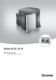
Abgasführung<br />
Für die Heizung <strong><strong>Truma</strong>tic</strong> E <strong>2400</strong> E darf für den Einbau mit<br />
Wandkamin nur das <strong>Truma</strong> Abgasrohr AA 24 (Art.-Nr. 39420-<br />
00) und das Verbrennungsluft-Zuführungs rohr ZR 24 (Art.-Nr.<br />
39440-00) verwendet werden, da das Gerät nur mit diesen<br />
Rohren geprüft und zugelassen ist.<br />
Nach jeder Demontage der Abgasfüh rung muss ein<br />
neuer O-Ring montiert werden!<br />
Zulässige Rohrlängen<br />
1. Inneneinbau mit Wandkamin (siehe Einbauvarianten 1,<br />
Seite 2):<br />
– Rohrlängen bis max. 70 cm können beliebig steigend<br />
oder mit einem Gefälle von max. 30 cm verlegt werden.<br />
– Rohrlängen von 70 cm bis max. 150 cm müssen steigend<br />
mit einem Steigungswinkel von mind. 45° verlegt<br />
werden.<br />
2. Unterflurmontage mit Wandkamin (siehe Einbauvariante<br />
4, Seite 2):<br />
Kamin-Doppelrohr Länge max. 70 cm,<br />
Verlegung beliebig steigend oder bis zu 30 cm fallend.<br />
Inneneinbau mit Wandkaminset<br />
Siehe Einbauvarianten Bild 1 (Seite 2).<br />
Montage des Wandkamins<br />
Wand kamin an einer möglichst geraden Fläche montieren, die<br />
allseitig vom Wind umströmt werden kann. Öffnung (8) mit<br />
Ø 70 mm bohren (bei Hohlräu men im Bereich der Kamin bohrung<br />
mit Holz ausfüttern). Abdichtung erfolgt mit beigelegter<br />
Gummidichtung (10). Bei strukturierten Oberflä chen mit plastischem<br />
Karosserie-Dichtmittel – kein Silikon – bestreichen.<br />
Bei größeren Wandstärken zuerst Abgas-Doppelrohr von<br />
außen am Kamin anschließen.<br />
Gummidichtung (10) und Schelle (4) auf das Kamin-Innenteil<br />
(11) schieben.<br />
1 4<br />
Abgasrohr (1) am Anfang zusammenstauchen, dass Windung<br />
an Windung liegt, über den O-Ring (2a) auf den Stutzen (2) bis<br />
zum Bund (3) schieben (die Kamin-Abwinkelung zeigt nach<br />
oben) und Schelle (4) so festschrauben, dass der Bördelrand<br />
der Schelle um den Bund greift.<br />
Gezahnten Stutzen (9) mit plastischem Karosseriedichtmittel<br />
– kein Silikon! – bestreichen und Verbrennungsluft-Zuführungsrohr<br />
(5) darüber schieben.<br />
2a<br />
3<br />
2<br />
Kamininnenteil (11) mit 3 Schrauben (12) befestigen (Einbaulage<br />
beachten! Der <strong>Truma</strong> Schriftzug muss unten sein).<br />
Kamin-Außenteil (13) aufsetzen und mit 2 Schrauben (14)<br />
anschrauben.<br />
Nach jeder Demontage muss ein neuer O-Ring montiert<br />
werden!<br />
Befestigung der Heizung<br />
Je nach Einbaulage Heizung mit Befestigungsbügel (a) oder<br />
Befestigungswinkeln (b) fest anschrauben.<br />
Abgas-Doppelrohr ggf. mit Rohrschelle ZR 24 (c) an der Wand<br />
befestigen (Teile im Beipack).<br />
Doppelrohranschluss an die Heizung<br />
Abgasrohr (1) am Anfang zusammenstauchen, dass Windung<br />
an Windung liegt. Schelle (4) über das Abgasrohr (1) schieben.<br />
Ab gas rohr über den O-Ring auf den Stutzen (2) bis zum<br />
Bund (3) schieben. Mit Schelle (4) so befestigen, dass der<br />
Bördelrand der Schelle um den Bund greift. Verbrennungs luft-<br />
Zuführungsrohr (5) auf Stutzen (6) mit Schelle (7) befestigen.<br />
Nach jeder Demontage muss ein neuer O-Ring montiert<br />
werden!<br />
Unterflurmontage mit Wandkaminset<br />
Siehe Einbauvariante Bild 4 (Seite 2).<br />
Wandkamin an einer möglichst geraden Fläche an einer Außenwand<br />
(Fahrzeug schürze) einbauen (siehe „Inneneinbau mit<br />
Wandkaminset“).<br />
Falls der Wandkamin mit Haltewinkeln o. Ä. unter dem<br />
Boden eingebaut wird, muss der Fahrzeugboden dicht<br />
sein (siehe „Inneneinbau mit Bodenkamin“)!<br />
Befestigung der Heizung<br />
Die 3 Befestigungsbügel (1, 2 + 3) an der Heizung anschrauben.<br />
Heizung mit den Laschen 1 + 2 fest am Fahrzeugboden<br />
anschrauben. Montagebügel (4 – Zubehör Art.-Nr. 39050-<br />
74000) und Lasche (3) mit Schrau ben (5) befestigen. Federringe<br />
unter alle Schrauben köpfe und Muttern legen.<br />
7
Inneneinbau mit Bodenkamin<br />
Siehe Einbauvariante Bild 2 (Seite 2).<br />
Bei der Verwendung des Bodenkamins müssen eventuelle<br />
Einschränkungen in den nationalen Vorschriften des Bestimmungslandes<br />
beachtet werden.<br />
In der Regel wird die Heizung mit langem Bodenkamin eingebaut.<br />
Der Einbau mit kur zem Bodenkamin ist nur bis Bodenstärken<br />
von 10 mm zulässig.<br />
Die Heizung darf nur stehend montiert werden. Bei Fahrzeugen,<br />
die Wohn- und Aufenthaltszwecken dienen, muss<br />
der Fahrzeug boden dicht sein und darf keine Öffnungen<br />
zum Innenraum aufweisen, wie z. B. Lüftungsöffnungen für<br />
Kühlschrank, offene Pedal durchbrüche, Belüftungs schieber,<br />
hohle Doppelböden.<br />
Der Bodenkamin darf nicht im Spritzbereich der Räder liegen<br />
(evtl. Spritzschutz an bringen) und muss freistehen, damit die<br />
Funktion nicht durch Träger, Achsen, Traver sen u. Ä. gestört<br />
wird. Außer dem müssen mindestens drei Seiten unterhalb des<br />
Fahr zeugbodens frei sein, um ein ungehindertes Abziehen der<br />
Abgase sicherzustellen.<br />
Montage des Bodenkamins<br />
Die rechteckige Öffnung für den Abgasaustritt (7) muss quer<br />
zur Fahrtrichtung stehen.<br />
8<br />
Am Bodenkamin dürfen keine Veränderungen vorgenommen<br />
werden!<br />
Schablone für die Positionierung von Bodenkamin und Befestigungsbohrungen<br />
entsprechend der Ein baulage der Heizung<br />
auflegen. Die Punkte vorstechen oder anzeichnen. Die Öffnung<br />
(1) Ø 64 mm für den Bodenkamin bohren. Zwi schen Kamin<br />
und Fahrzeug boden mit plastischem Karosseriedichtmittel<br />
(2) – kein Silikon! – abdichten. Bodenkamin (3) mit Schrau ben<br />
(4) befestigen. Abweiser (5) aufsetzen und mit Schraube (6)<br />
befestigen.<br />
Befestigung der Heizung<br />
Heizung auf Kaminöffnung aufsetzen und mit 4 Befestigungswinkeln<br />
fest anschrauben.<br />
Außenmontage mit kurzem Boden kamin<br />
Siehe Einbauvariante Bild 3 (Seite 2).<br />
Die Heizung darf nur mit Kaminstutzen senkrecht nach unten<br />
montiert werden. Die Heizung kann außerhalb des Fahrzeuges<br />
an einer senkrechten Wand (z. B. an der Fahrerhaus-Rückwand<br />
oder an der Aufbau-Stirnwand eines LKW) befestigt<br />
werden. Bei Sattelschleppern auf ausreichenden Abstand<br />
zwischen Fahrerhaus-Rückwand und Sattelauflieger achten<br />
(Dreh- und Knickbewegungen berücksichtigen).<br />
Montage des Bodenkamins<br />
Am Bodenkamin dürfen keine Veränderungen vorgenommen<br />
werden!<br />
Abweiser (1) aufsetzen und mit Schraube (2) befestigen. Kamin<br />
(3) auf den Abgasstutzen der Heizung (4) stecken. Die Befestigungslöcher<br />
seitlich unterhalb des Bundes durchbohren<br />
(Bohrer Ø 2,5 mm). Kamin mit 2 Schrauben (5) befestigen.<br />
Befestigung der Heizung<br />
Die 3 Laschen (8, 9 + 10) an der Heizung anschrauben. Heizung<br />
mit den Laschen 8 + 9 an der Außenwand mit mind. M 5<br />
Durchgangsschrauben anschrauben. Montagebügel (11 – Zubehör<br />
Art.-Nr. 39050-74000) oben zusammen mit Lasche (10)<br />
befestigen und unten anschrauben (12). Federringe unter alle<br />
Schraubenköpfe und Muttern legen.<br />
Warmluftverteilung und Umluft-<br />
Rückführung bei Inneneinbau<br />
Warmluftverteilung<br />
Heizluftansaugöffnungen müssen so angeordnet sein, dass<br />
ein Ansaugen von Abgasen des Fahrzeugmotors und des<br />
Heizgerätes nicht erfolgen kann. Durch bauliche Maßnahmen<br />
muss gewährleistet sein, dass die in das Fahrzeug innere geführte<br />
Heizluft nicht verunreinigt werden kann (z. B. durch<br />
Öldämpfe). Das ist erfüllt zum Beispiel bei Luftheizungen im<br />
Umluftbetrieb sowohl bei Innenraum einbauten als auch bei<br />
Außeneinbau (bei Luftheizungen im Frischluftbetrieb darf die<br />
Frischluft nicht aus dem Motorraum oder in der Nähe des<br />
Auspuffs oder der Abgasausströmöffnung der Heizung<br />
angesaugt werden).<br />
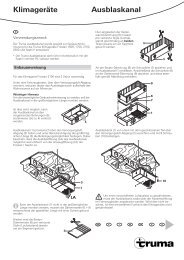
Die Warmluft (W) wird von der Heizung ausgeblasen, entweder<br />
direkt oder über ein Warmluftrohr VR 80 (Ø 80 mm).<br />
Gitter am Warmluftaustritt der Heizung entfernen. Rohr VR 80<br />
(Ø 80 mm) anschließen. Nach dem Setzen eines Teiles zur<br />
Rohrverzweigung können auch die Rohre VR (Ø 72 mm), ÜR<br />
(Ø 65 mm) oder ZR 18 (Ø 49 mm) weiterverlegt werden.
Um eine Überhitzung zu vermeiden, muss zumindest ein<br />
Luftstrang unverschließbar sein (Schwenkdüse SCW 2).<br />
Alle Rohranschlüsse mit Blechschrauben sichern. Rohre mit<br />
Schellen befestigen.<br />
Das Warmluftsystem wird für jeden Fahrzeugtyp individuell<br />
im Baukastenprinzip ausgelegt. Dafür steht ein reichhaltiges<br />
Zubehör-Programm zur Verfügung (siehe Prospekt). Skizzen<br />
mit optimalen Ein bauvorschlägen für Warm luftanlagen können<br />
über das <strong>Truma</strong> Servicezentrum kostenlos angefordert<br />
werden.<br />
Umluft-Rückführung<br />
Die Umluft (U) wird von der Heizung wieder angesaugt,<br />
entweder direkt oder über ein Rohrstück VR 80 (Ø 80 mm).<br />
1. Direktansaugung: Ist die Heizung in einem Staukasten o. Ä.<br />
eingebaut, in diesem 2 Bohrungen Ø 75 mm oder eine<br />
entsprechend große Öffnung für die Umluft-Rückführung<br />
anbringen.<br />
Luftwege zur Heizung nicht zustauen!<br />
2. Über ein Rohrstück VR 80 (1) Ø 80 mm (max. 1 m Länge)<br />
kann Umluft außerhalb des Stauraums angesaugt und zur<br />
Heizung rückgeführt werden. Der Stauraum ist dann voll<br />
nutzbar.<br />
Schutzgitter aus dem Stutzen (3) ausbauen. Rohrstück (1) in<br />
den Gitterstutzen stecken und mit vorhandenen Schrauben<br />
befestigen. Schwenkdüse SCW 2 am Rohrende (4) anbringen.<br />
Warmluftzuführung und Umluft-<br />
Rück füh rung bei Außen montage<br />
Siehe Einbauvarianten Bild 3 + 4 (Seite 2).<br />
Die Warmluft-Zufüh rung und die Umluft-Rückführung zwischen<br />
Heizung und Fahrzeug ist mit den flexiblen Luftrohren<br />
LF 18 (Ø 83 mm, Länge 60 cm) herzustellen. Die Luftrohre<br />
können beliebig gekürzt werden. Ein Schutzkasten über die<br />
ganze Heizungsanlage schützt diese vor Beschädi gung und<br />
Witterungsein flüssen und dient als zusätzliche Isolierung.<br />
Anschluss der Rohre an die Heizung<br />
Die beiden Schutzgitter aus der Heizung ausbauen. Die beiden<br />
Rohrstücke LF 18 (1) an den versteiften Enden (2) mit<br />
plastischem Karosseriedichtmittel einstreichen und in die Öffnungen<br />
der Heizung (W + U) schieben. Mit 2 Blechschrauben (3)<br />
sichern. Die Rohrverbindung erfordert eine korrekte Montage,<br />
da sonst Spritzwasser in die Heizung eindringen kann!<br />
Montage der Rohre bei Durchführungen<br />
Zwei Öffnungen Ø 73 mm (W + U) bohren. Die Anschlussstücke<br />
(4) am Flansch mit plastischem Karosseriedichtmittel einstreichen<br />
und anschrauben, bei der Bohrung (U) das Schutzgitter<br />
(5) dazwischenlegen.<br />
Die beiden Rohrstücke LF 18 (6) bei Bedarf entsprechend<br />
ablängen, innen mit plastischem Karosseriedichtmittel einstreichen<br />
und auf die Anschlussstücke (4) schieben. Mit<br />
Schneckengewindeschelle (7) befestigen.<br />
Im Innenraum über der Öffnung (W) das Anschlussstück (8)<br />
anschrauben (kann auch mit dem außenliegenden Anschlussstück<br />
gemeinsam verschraubt werden). Bei hohlen Doppelwänden<br />
ist der Zwischenraum abzudichten.<br />
Warmluftverteilung<br />
Rohr VR 80 (9) Ø 80 mm anschließen und mit Blechschraube<br />
(10) sichern. Auf das Anschluss stück (8) können auch die verschiedenen<br />
Teile zur Rohrverzweigung aufgesetzt werden, die<br />
eine Weiterver legung der Rohre VR (Ø 72 mm), ÜR (Ø 65 mm)<br />
oder ZR 18 (Ø 49 mm) ermöglichen.<br />
Um Überhitzung zu vermeiden, muss zumindest ein<br />
Luftstrang unverschließbar sein (Schwenkdüse SCW 2).<br />
Alle Rohranschlüsse mit Blechschrauben sichern. Rohre mit<br />
Schellen befestigen.<br />
Das Warmluftsystem wird für jeden Fahrzeugtyp individuell<br />
im Baukastenprinzip ausgelegt. Dafür steht ein reichhaltiges<br />
Zubehör-Programm zur Verfügung (siehe Prospekt). Skizzen<br />
mit optimalen Ein bauvorschlägen für Warm luftanlagen in allen<br />
gängigen Reisemobiltypen können über das <strong>Truma</strong> Servicezentrum<br />
kostenlos angefordert werden.<br />
9
Umluft-Rückführung<br />
Durch die Öffnung (U) muss die Heizung ausreichend<br />
Umluft ansaugen können. Erfolgt die Umluft-Rückführung<br />
innerhalb eines Staukastens, in diesem zwei Bohrungen<br />
(13) mit je Ø 75 mm oder eine entsprechend große Öffnung<br />
anbringen.<br />
10<br />
Luftwege zur Heizung nicht zustauen<br />
Soll der Stauraum voll nutzbar bleiben, kann die Rückluft über<br />
eine Schwenkdüse SCW 2 und ein Rohrstück VR 80 angesaugt<br />
werden. Hierzu über der Öffnung (U) ein Anschlussstück<br />
anschrauben. Gesamtlänge bis zur Heizung max. 2 m!<br />
Montage des Bedienteils<br />
Bei Verwendung von fahrzeug- bzw. herstellerspezifischen<br />
Bedienteilen, muss der elektrische Anschluss<br />
gemäß den <strong>Truma</strong> Schnittstellenbeschreibungen erfolgen.<br />
Jede Veränderung der dazugehörigen <strong>Truma</strong> Teile führt zum<br />
Erlöschen der Garantie sowie zum Ausschluss von Haftungsansprüchen.<br />
Der Einbauer (Hersteller) ist für eine Gebrauchs -<br />
anweisung für den Benutzer sowie für die Bedruckung der<br />
Bedienteile verantwortlich!<br />
Bei der Platzwahl beachten, dass die Bedienteile nicht direkter<br />
Wärmeabstrahlung ausgesetzt sein dürfen. Länge des<br />
Anschluss kabels 4 m oder 10 m.<br />
Ist eine Montage nur hinter Vor hängen oder ähnlichen Plätzen<br />
mit Temperaturschwankungen möglich, so muss ein Fernfühler<br />
für die Raumtemperatur verwendet werden (Zubehör).<br />
Montage des Bedienteils mit Drehschalter<br />
Ist eine Unterputzmontage des Bedienteils nicht möglich,<br />
liefert <strong>Truma</strong> auf Wunsch einen Aufputzrahmen (1 – Art.-<br />
Nr. 40000-52600) als Zubehör.<br />
Loch Ø 55 mm bohren.<br />
Das Bedienteilkabel (2) am Bedienteil (3) anstecken und anschließend<br />
die hintere Abdeckkappe (4) als Zugentlastung<br />
aufstecken.<br />
Das Kabel nach hinten durchschieben und zur elektronischen<br />
Steuereinheit verlegen.<br />
Bedienteil mit 4 Schrauben (5) befestigen und Abdeckrahmen<br />
(6) aufstecken.<br />
Als Abschluss zu den Abdeckrahmen liefert <strong>Truma</strong> als<br />
Zubehör Seitenteile (7) in 8 verschiedenen Farben (bitte<br />
fragen Sie Ihren Händler).<br />
2<br />
1<br />
Ø 55 mm<br />
4<br />
3<br />
5<br />
7 6<br />
7<br />
Montage des Bedienteils mit Schiebeschalter<br />
Für vorhandene Einbauausschnitte.<br />
Abdeckblende aus dem Einbauausschnitt entfernen.<br />
Bedienteilkabel (12) am Bedienteil (14) anstecken, durch den<br />
Einbauausschnitt nach hinten durchführen und zur elektronischen<br />
Steuereinheit verlegen.<br />
Bedienteil (14) eindrücken, bis Frontfläche bündig ist.<br />
Wenn kein Einbauausschnitt vorhanden ist, kann das<br />
Bedienteil mit dem mitgelieferten Unterputzrahmen<br />
montiert werden.<br />
Ist eine Unterputzmontage nicht möglich, liefert <strong>Truma</strong> auf<br />
Wunsch einen Aufputzrahmen (Art.-Nr. 39050-11600) als<br />
Zubehör.<br />
Montage der elektronischen Steuereinheit<br />
Deckel der Steuer einheit abschrauben.<br />
Die Stecker an der elektronischen Steuereinheit dürfen<br />
nur abgezogen oder aufgesteckt werden, wenn zuvor<br />
die Versorgungsspannung abgeklemmt wurde. Stecker<br />
gerade abziehen!<br />
Stecker vom Bedienteilkabel (1) gemäß Bild auf die rote<br />
Stiftenleiste der Steuereinheit aufstecken.<br />
Wird eine Zeitschaltuhr oder ein Fernfühler eingebaut, ist<br />
deren Stecker an der schwarzen Stiftenleiste anzustecken.<br />
Bei gleichzeitiger Verwendung von mehreren Zubehörteilen<br />
erfolgt der Anschluss über die Multisteckdose (Zubehör).<br />
Unterteil an gut zugänglicher, vor Nässe geschützter Stelle<br />
mit 2 Schrauben befestigen (darf nicht über 65° C erwärmt<br />
werden).<br />
Deckel der Steuereinheit aufschrauben.<br />
Bei außerhalb des Fahrzeuges montierten Heizungen muss<br />
die elektronische Steuerein heit im Fahrzeug-Innenraum gegen<br />
Feuchtigkeit und Be schädigung geschützt montiert werden.<br />
Im Boden bzw. in der Wand eine Öffnung von Ø 25 mm bohren,<br />
Stecker (2) des 20-poligen Kabels von der Steuereinheit<br />
abziehen und durch die Öffnung führen. Mit Kabeltülle abdichten.<br />
Stecker wieder aufstecken.<br />
In Ausnahmefällen kann die elektronische Steuereinheit mit<br />
Schutzkasten für außenliegende Elektronik (Zubehör Art.-Nr.<br />
39950-00) außerhalb des Fahrzeuges montiert werden.
Elektrischer Anschluss 12 V / 24 V<br />
Elektrische Leitungen, Schalt- und Steuergeräte für Heizgeräte<br />
müssen im Fahrzeug so angeordnet sein, dass ihre einwandfreie<br />
Funktion unter normalen Betriebsbedin gungen nicht<br />
beeinträchtigt werden kann. Alle nach außen führenden Leitungen<br />
müssen am Durchbruch spritzwasserdicht verlegt sein.<br />
Vor Beginn der Arbeit an elektrischen Teilen muss das<br />
Gerät von der Stromversorgung abgeklemmt werden.<br />
Ausschal ten am Bedienteil reicht nicht!<br />
Bei Elektro-Schweißarbeiten an der Karosserie muss der<br />
Geräteanschluss vom Bordnetz getrennt werden.<br />
Bei Verpolung der Anschlüsse besteht Gefahr von<br />
Kabelbrand. Außerdem erlischt jeder Garantie- oder<br />
Haftungs anspruch!<br />
Das rote Kabel ist Plus, das blaue Minus!<br />
Gerät am abgesicherten Bord netz (Zentralelektrik 5 – 10 A) mit<br />
Kabel 2 x 1,5 mm ² , bei Längen über 6 m mit Kabel 2 x 2,5 mm²<br />
anschließen. Minusleitung an Zentral mas se. Bei direktem<br />
An schluss an die Batterie ist die Plus- und Minusleitung abzusichern.<br />
Anschlüsse in Faston, voll isoliert (Kfz-Flach stecksystem<br />
6,3 mm) ausführen.<br />
An die Zuleitung dürfen keine weiteren Verbraucher<br />
angeschlossen werden!<br />
Bei Verwendung von Netzteilen ist zu beachten, dass die<br />
Ausgangsspannung zwischen 11 V und 15 V liegt und<br />
die Wechselspannungswelligkeit < 1,2 Vss beträgt.<br />
Für den Anschluss mehrerer 12 V-Geräte empfehlen wir das<br />
<strong>Truma</strong> Batterie-Ladegerät NT 12/ 3-18 (Art.-Nr. 39901-01).<br />
Dieses Ladegerät (18 A Ladestrom) ist für das Laden von<br />
Blei-Säure- oder Blei-Gel-Batterien geeignet. Andere Ladegeräte<br />
sind nur mit einer Batterie 12 V als Puffer zu verwenden.<br />
Netz- bzw. Stromversorgungsgeräte müssen einen geregelten<br />
12 V-Ausgang besitzen (Wechselspannungsanteil kleiner als<br />
1,2 Vss).<br />
Um die Batteriekapazität zu schonen, empfehlen wir<br />
Sonnenkollektoren. Bitte informieren sie sich darüber im<br />
Fachhandel.<br />
Gasanschluss<br />
Der Betriebsdruck der Gasversorgung 50 mbar muss<br />
mit dem Betriebsdruck des Gerätes (siehe Fabrikschild)<br />
über einstimmen.<br />
Das Gaszuleitungsrohr Ø 8 mm muss mit einer Schneidringverschraubung<br />
am Anschlussstutzen angeschlossen werden.<br />
Beim Festziehen sorgfältig mit einem zweiten Schlüssel<br />
gegenhalten!<br />
Der Gasanschlussstutzen am Gerät darf nicht gekürzt oder<br />
verbogen werden.<br />
Vor dem Anschluss an das Gerät sicherstellen, dass die Gasleitungen<br />
frei von Schmutz, Spänen u. Ä. sind!<br />
Die Rohrverlegung ist so zu wählen, dass für Service-Arbeiten<br />
das Gerät wieder ausgebaut werden kann.<br />
In der Gaszuleitung ist die Anzahl der Trennstellen in von<br />
Personen benutzten Räumen auf die technisch unvermeidbare<br />
Anzahl zu begrenzen.<br />
Die Gasanlage muss ab dem Mitteldruckregler den technischen<br />
und administrativen Bestimmungen des jeweiligen<br />
Verwendungslandes entsprechen. Nationale Vorschriften<br />
und Regelungen (in Deutschland z. B. das DVGW-Arbeitsblatt<br />
G 609 Entwurf für Fahrzeuge) müssen beachtet werden.<br />
Nach der Montage der Gasanlage muss die Hochdruckseite<br />
einmalig von einen Sachverständigen des TÜV überprüft<br />
werden.<br />
Funktionsprüfung<br />
Nach dem Einbau muss die Dichtigkeit der Gaszuleitung<br />
nach der Druckabfallmethode geprüft werden. Eine Prüfbescheinigung<br />
(in Deutschland z. B. gemäß DVGW-Arbeitsblatt<br />
G 609 Entwurf für Fahrzeuge) ist auszustellen.<br />
Anschlie ßend gemäß der Gebrauchsanweisung sämtliche<br />
Funktionen des Gerätes prüfen.<br />
Die Gebrauchsanweisung mit ausgefüllter Garantiekarte ist<br />
dem Fahrzeughalter auszu händigen.<br />
Das Fabrikschild der Gebrauchs- und Einbauan weisung<br />
entnehmen und an gut sichtbarer, gegen Beschädigungen<br />
geschützter Stelle auf die Heizung kleben. Das Jahr<br />
der ersten Inbetriebnahme muss auf dem Fabrikschild angekreuzt<br />
werden.<br />
Warnhinweise<br />
Der dem Gerät beigegebene gelbe Aufkleber mit den Warnhinweisen<br />
muss durch den Einbauer bzw. Fahrzeughalter an<br />
einer für jeden Benutzer gut sichtbaren Stelle im Fahrzeug<br />
angebracht werden! Fehlende Aufkleber können bei <strong>Truma</strong><br />
angefordert werden.<br />
11
<strong>Truma</strong> Hersteller-Garantieerklärung<br />
1. Garantiefall<br />
Der Hersteller gewährt Garantie für Mängel des Gerätes, die<br />
auf Material- oder Fertigungsfehler zurückzuführen sind. Daneben<br />
bestehen die gesetzlichen Gewährleistungsansprüche<br />
gegen den Verkäufer fort.<br />
Der Garantieanspruch besteht nicht<br />
– für Verschleißteile und bei natürlicher Abnutzung,<br />
– infolge Verwendung von anderen als <strong>Truma</strong> Originalteilen<br />
in den Geräten und bei Verwendung ungeeigneter<br />
Gasdruckregler,<br />
– infolge Nichteinhaltung der <strong>Truma</strong> Einbau- und Gebrauchsanweisungen,<br />
– infolge unsachgemäßer Behandlung,<br />
– infolge unsachgemäßer, nicht von <strong>Truma</strong> veranlass ter<br />
Transportverpackung.<br />
2. Umfang der Garantie<br />
Die Garantie gilt für Mängel im Sinne von Ziffer 1, die innerhalb<br />
von 24 Monaten seit Abschluss des Kaufvertrages zwischen<br />
dem Verkäufer und dem Endverbraucher eintreten. Der<br />
Hersteller wird solche Mängel durch Nacherfüllung beseitigen,<br />
das heißt nach seiner Wahl durch Nach besserung oder Ersatzlieferung.<br />
Leistet der Hersteller Garantie, beginnt die Garantiefrist<br />
hinsichtlich der reparierten oder ausgetauschten Teile<br />
nicht von neuem, sondern die alte Frist läuft weiter. Weitergehende<br />
Ansprüche, insbesondere Schadensersatzansprüche<br />
des Käufers oder Dritter sind ausgeschlos sen. Die Vorschriften<br />
des Produkthaftungs gesetzes bleiben unberührt.<br />
Die Kosten der Inanspruch nahme des <strong>Truma</strong> Werks kun dendienstes<br />
zur Beseitigung eines unter die Garantie fallenden<br />
Mangels – insbesondere Transport-, Wege-, Arbeits- und<br />
Materialkosten – trägt der Hersteller, soweit der Kundendienst<br />
innerhalb von Deutschland eingesetzt wird. Kundendiensteinsätze<br />
in anderen Ländern sind nicht von der Garantie gedeckt.<br />
Zusätzliche Kosten aufgrund erschwerter Aus- und Einbaubedingungen<br />
des Gerätes (z. B. Demontage von Möbel- oder<br />
Karosserieteilen) können nicht als Garantieleistung anerkannt<br />
werden.<br />
3. Geltendmachung des Garantiefalles<br />
Die Anschrift des Herstellers lautet:<br />
<strong>Truma</strong> <strong>Gerätetechnik</strong> <strong>GmbH</strong> & <strong>Co</strong>. <strong>KG</strong>,<br />
Wernher-von-Braun-Straße 12,<br />
85640 Putzbrunn.<br />
In Deutschland ist bei Störungen grundsätzlich das <strong>Truma</strong><br />
Servicezentrum zu benachrichtigen; in anderen Ländern stehen<br />
die jeweiligen Servicepartner zur Verfügung (siehe <strong>Truma</strong><br />
Serviceheft oder www.truma.com). Beanstandungen sind näher<br />
zu bezeichnen. Ferner ist die ordnungsgemäß ausgefüllte<br />
Garantie-Urkunde vorzulegen oder die Fabriknummer des<br />
Gerätes sowie das Kaufdatum anzugeben.<br />
Damit der Hersteller prüfen kann, ob ein Garantiefall vorliegt,<br />
muss der Endverbraucher das Gerät auf seine Gefahr zum<br />
Hersteller bringen oder ihm übersenden. Bei Schäden an Heizkörpern<br />
(Wärmetau scher) ist der Gasdruckregler ebenfalls mit<br />
einzusenden.<br />
Bei Einsendung ins Werk hat der Versand per Frachtgut zu erfolgen.<br />
Im Garantiefall übernimmt das Werk die Transportkosten<br />
bzw. Kosten der Einsendung und Rücksendung. Liegt kein<br />
Garantiefall vor, gibt der Hersteller dem Kunden Bescheid und<br />
nennt die vom Hersteller nicht zu übernehmenden Reparaturkosten;<br />
in diesem Fall gehen auch die Versandkosten zu<br />
Lasten des Kunden.<br />
12
<strong><strong>Truma</strong>tic</strong> E <strong>2400</strong> E<br />
Natural gas heater with electronic control, built-in air distribution<br />
and thermostat<br />
General safety notes<br />
If the gas system is leaking or if there is a smell of gas:<br />
– extinguish all naked flames<br />
– do not smoke<br />
– switch off the appliances<br />
– shut off the gas cylinder<br />
– open windows and door<br />
– do not actuate any electrical switches<br />
– have the entire system checked by an expert!<br />
Repairs may only be carried out by an expert!<br />
A new O-ring must always be installed after dismantling the<br />
exhaust duct!<br />
Any modifications to the unit (including the exhaust duct and<br />
the cowl) or the use of spare parts and accessories that are<br />
important to the operation of the system (e.g. the time switch)<br />
that are not original <strong>Truma</strong> parts and failure to follow the installation<br />
and operating instructions will cancel the warranty<br />
and indemnify <strong>Truma</strong> from any liability claims. It also becomes<br />
illegal to use the appliance, and in some countries this even<br />
makes it illegal to use the vehicle.<br />
The operating pressure for the gas supply is 50 mbar and<br />
must correspond to the operating pressure of the appliance<br />
(see data plate).<br />
Natural gas heaters must be connected to the vehicles own<br />
CNG system according the relevant technical and administrative<br />
regulations applicable in the particular country of designation.<br />
In Germany, e.g. in accordance with DVGW Worksheet<br />
G 609 Draft and VdTÜV <strong>Co</strong>de of Practice 757. The <strong>Truma</strong> work<br />
instruction “Natural Gas (CNG) Heaters in Motor Vehicles”<br />
takes the relevant requirements into consideration.<br />
For vehicles for commercial use, the relevant accident prevention<br />
regulations issued by the professional associations are to<br />
be respected (BGV D 34).<br />
The testing of the low pressure gas supply for heating<br />
and the equipment itself must be repeated in Germany by<br />
an expert (DVFG, TÜV, DEKRA) in accordance with G 609<br />
Draft within the same time periods as the main inspection<br />
(§ 29 StVZO) and confirmed on an appropriate test certificate<br />
(in Germany e.g. G 609 Draft, i.e. in the <strong>Truma</strong> test certificate).<br />
The keeper of the vehicle is responsible for arranging the<br />
inspection.<br />
Pressure regulating equipment and hoses must be replaced<br />
with new ones no more than 10 years after the date of manufacture<br />
(every 8 years if used commercially). This is the<br />
responsibility of the operator.<br />
Gas equipment must not be used when refuelling, in multistorey<br />
car parks, in garages or on ferries.<br />
During the initial operation of a brand new appliance (or after<br />
it has not been used for some time), a slight amount of fumes<br />
and smell may be noticed for a short while. This can be remedied<br />
by running the heater at maximum output and ensuring<br />
adequate room ventilation.<br />
If the burner makes an un-usual noise or if the flame lifts off, it<br />
is likely that the regulator is faulty and it is essential to have it<br />
checked.<br />
Items sensitive to heat (e.g. spray cans) must not be stored<br />
in the installation area, since excess temperatures may under<br />
certain circumstances be incurred there.<br />
Only pressure regulating equipment that is compliant with<br />
EN 12864 or compliant with DIN 4811 in Germany (in vehicles)<br />
with a fixed output pressure of 50 mbar may be used for<br />
the gas system. The flow rate of the pressure control device<br />
must correspond to at least the maximum consumption of all<br />
devices installed by the system manufacturer.<br />
<strong>Co</strong>ntroller connecting hoses that meet national regulations<br />
must always be used in the respective country for which the<br />
equipment is destined. These hoses must be checked regularly<br />
for brittleness. Winter-proof special hoses must always<br />
be used if the equipment is operated during the winter.<br />
If the pressure regulator is exposed to weather conditions<br />
– especially on trucks – always make sure to protect the regulator<br />
using the <strong>Truma</strong> protective cover (standard accessory in<br />
truck attachment kit).<br />
Important operating notes<br />
If the chimney has been placed near or directly beneath an<br />
opening window, the device must be equipped with an automatic<br />
shut-off device in order to prevent operation with the<br />
window open.<br />
The integrity and tight fit of the exhaust gas double duct must<br />
be checked regularly, particularly at the end of long trips. Also<br />
check the mounting of the appliance and the cowl.<br />
Following a blow-back (misfire) always have the exhaust gas<br />
system checked by an expert!<br />
If appliances are assembled on the outside of the vehicle,<br />
regularly check the flexible air ducts for damage. A damaged<br />
duct could lead to exhaust gas entering the vehicle.<br />
Always keep the cowl for conducting exhaust gas and supplying<br />
combustion air, free from contamination (slush, leaves<br />
etc.).<br />
The installed temperature limiter shuts off the gas supply if the<br />
appliance becomes too hot. Therefore do not shut the warm<br />
air outlets and the opening for the returning circulating air.<br />
If the electronic control p.c.b. is defective, return it well<br />
packed. If you fail to do so, guarantee claims shall no longer<br />
be valid. Only use original p.c.b. as a spare part!<br />
Always use original <strong>Truma</strong> parts for maintenance and<br />
repair work!<br />
For conducting the exhaust gas under the floor, the vehicle<br />
floor must be sealed tight. There must also be three open<br />
sides beneath the vehicle floor to ensure unhindered escape<br />
of the exhaust gas (snow, aprons etc.).<br />
13
14<br />
Operating instructions<br />
Intended use<br />
This appliance has been designed for installation in natural gas<br />
operated vehicles. It is not approved for installation in boats.<br />
Other applications are also possible following consultation<br />
with <strong>Truma</strong>.<br />
Always observe the opera ting instructions and “Important<br />
operating notes” prior to starting! The vehicle owner<br />
is responsible for the correct operation of the appliance!<br />
The installer or vehicle owner must apply the yellow sticker<br />
with the warning information, which is enclosed with the appliance,<br />
to a place in the vehicle where it is clearly visible to all<br />
users! Ask <strong>Truma</strong> to send you stickers, if necessary.<br />
<strong>Co</strong>ntrol panel with sliding switch<br />
a = Slide valve<br />
Heating – Off – Ventilation<br />
b = Slide valve for<br />
high setting (large flame symbol)<br />
low setting (small flame symbol)<br />
<strong>Co</strong>ntrol panel with rotary switch<br />
b<br />
a<br />
<strong><strong>Truma</strong>tic</strong> E<br />
5<br />
c = “Heating” rotary switch<br />
high setting (large flame symbol)<br />
low setting (small flame symbol)<br />
d = “Off” rotary switch<br />
e = “Ventilation” rotary switch<br />
high setting (large symbol)<br />
low setting (small symbol)<br />
Switching on the Heating<br />
– Remove cowl cap.<br />
– Open gas extraction valve.<br />
9<br />
– Open quick-acting valve in the gas supply line.<br />
7<br />
– Adjust desired room temperature at rotary knob.<br />
– Switching the heating on:<br />
<strong>Co</strong>ntrol panel with sliding switch<br />
Set the switch (a) to Heating and switch (b) to the desired<br />
output setting.<br />
<strong>Co</strong>ntrol panel with rotary switch<br />
Set the rotary switch to the desired output setting (c).<br />
If the outside temperature is low, switch to high setting.<br />
The <strong><strong>Truma</strong>tic</strong> E heater has been tested and approved for<br />
operation, also when the vehicle is moving. The burner<br />
with fan assistance guarantees satisfactory operation, even<br />
under extremely windy conditions. National restrictions for<br />
the operation of gas equipment while driving may need to be<br />
taken into consideration.<br />
3<br />
1<br />
e<br />
d<br />
c<br />
Switching on the Ventilation<br />
<strong>Co</strong>ntrol panel with sliding switch:<br />
Set switch (a) to Ventilation and switch (b) to the desired<br />
output setting.<br />
<strong>Co</strong>ntrol panel with rotary switch:<br />
Set the rotary switch to the desired output setting (e).<br />
Switching off<br />
Set the sliding switch (a) or the rotary switch (d) to the centre.<br />
If the appliance is switched off after a heating phase, the fan<br />
can continue running in order to make use of the residual<br />
heat.<br />
If the device is not used for a long period, put on cowl cover<br />
and close quick-acting valve in the gas supply line.<br />
Green indicator lamp “Operation”<br />
(under rotary control knob)<br />
When the appliance is switched on (heating or ventilation) the<br />
green indicator lamp must be illuminated (the fan is running).<br />
If the indicator lamp is not illuminated, possibly check the<br />
(main) switch. For this purpose observe respective instructions<br />
of the vehicle manufacturer.<br />
During the heating operation, while the flame is burning, the<br />
green indicator lamp lights up with twice the intensity. This<br />
also makes it possible to determine the instantaneous<br />
switching point of the room temperature.<br />
Fuses<br />
The device and control panel fuses are on the electronic<br />
control unit on the device.<br />
Device fuse (F1): 3.15 AT – slow – (EN 60127-2-3)<br />
<strong>Co</strong>ntrol panel fuse (F3): 1.6 AT – slow –<br />
The fine-wire fuse must only be replaced by a fuse of the<br />
same design.<br />
Red indicator lamp “Failure”<br />
Should a failure occur, the red indicator is illuminated permanently.<br />
Possible causes for the failure can be e.g. no gas,<br />
insufficient combustion air, heavily soiled rotor, defective fuse<br />
etc.. Deactivate by switching off and then switching on again.<br />
Opening a window to which a window switch is fitted<br />
and closing it again is the equivalent of switching off / on<br />
at the control panel (e.g. a fault reset)!<br />
Flash operation indicates that the operating voltage is too<br />
low or too high for the appliance (charge battery, if necessary).<br />
In Germany, always notify the <strong>Truma</strong> Service Centre if problems<br />
are encountered; in other countries the relevant service<br />
partners should be contacted (see <strong>Truma</strong> Service Booklet or<br />
www.truma.com).
Accessories<br />
1. <strong>Co</strong>ntrol unit VG 2<br />
for heaters of driver's cabs in tank vehicles, for the transportation<br />
of hazardous goods according to ADR (not to be<br />
used in combination with a time switch).<br />
2. Outside switch AS<br />
for switching the heater on and off from the outside of the<br />
vehicle, e.g. for cargo space heaters (available with 4 m or<br />
10 m connecting cables).<br />
3. Acoustic signalling device ASM<br />
gives an acoustic signal in event of a failure.<br />
4. Time switch ZUE / ZUE 2<br />
for pre-programming 3 switch-on times within 7 days, including<br />
4 m connecting cable (suitable for 12 V and 24 V<br />
vehicle electrical system).<br />
ZUE, part no. 39890-00, for installation in existing cut-outs,<br />
suitable for control panel with slide switch.<br />
ZUE 2 part no. 39891-00 with cover frame, suitable for<br />
control panel with rotary switch.<br />
5. Remote sensor FF<br />
monitors the room tem perature independent of the position<br />
of the control panel (available with 4 m or 10 m connecting<br />
cable).<br />
6. Multiple connector MSD<br />
for connecting several accessories (e.g. time switch and<br />
remote sensor).<br />
Extension cable for accessories<br />
items 1 – 6 of 4 m or 10 m (not illustrated).<br />
7. Direct switch DIS<br />
for operating the heater at high setting only, without temperature<br />
control (available with 4 m or 10 m connecting<br />
cable). Replaces control panel.<br />
Or direct fixed temperature switch DFS<br />
for operating the heater at a fixed temperature (40° C –<br />
70° C depending on the version). Replaces the control<br />
panel.<br />
All electrical accessories are fitted with a connector and can<br />
be connected individually.<br />
Technical data<br />
determined in accordance with EN 624 or <strong>Truma</strong> test conditions<br />
Type of gas<br />
Natural gas (from the vehicles own CNG system)<br />
Operating pressure<br />
50 mbar (see data plate)<br />
Rated thermal output<br />
High setting: <strong>2400</strong> W<br />
Low setting: 1200 W<br />
Gas consumption<br />
High setting: 240 l/h<br />
Low setting: 130 l/h<br />
Air flow rate<br />
High setting: approx. 78 m ³/h<br />
Low setting: approx. 49 m ³/h<br />
Current input at 12 V<br />
High setting: 1.1 A<br />
Low setting: 0.6 A<br />
Current input at 24 V<br />
High setting: 0.7 A<br />
Low setting: 0.4 A<br />
Standby<br />
0.01 A<br />
Weight<br />
approx. 4.7 kg<br />
Declaration of conformity<br />
The <strong><strong>Truma</strong>tic</strong> E <strong>2400</strong> E has been tested by the DVGW and<br />
complies with the gas equipment directive (90/396/EEC) and<br />
the other applicable EC directives. The following CE Product<br />
Ident. No. is available for EU countries: CE-0085AP0008.<br />
The heater complies with heater directive 2001/56/EC and<br />
supplements 2004/78/EC and 2006/119/EC and bears the type<br />
approval number: e1 00 0144.<br />
The heater complies with vehicle engine interference suppression<br />
directive 72/245/EEC with supplements 2004/104/EC,<br />
2005/83/EC and 2006/28/EC and bears type approval number:<br />
e1 03 2605.<br />
The heater complies with EMC directive 89/336/EEC and low<br />
voltage directive 72/23/EEC.<br />
15
16<br />
Installation instructions<br />
The installation and repair of the appliance is only to be<br />
carried out by an expert. Read the installation instruc-tions<br />
carefully prior to starting work and observe the instructions!<br />
The consequences of failing to adhere to the installation<br />
instructions or installing the equipment<br />
incorrectly are potentially fatal!<br />
Intended use<br />
This device was designed for installing in vehicles (motor<br />
homes, cars and commercial vehicles). Other applications are<br />
permitted after prior consultation with <strong>Truma</strong>.<br />
Installation inside busses (vehicle classes M2 and M3) is not<br />
permitted.<br />
Vehicles EX/II and EX/III<br />
<strong>Co</strong>mbustion heaters for gaseous fuels are not permitted.<br />
Approval<br />
Declaration of conformity<br />
The <strong><strong>Truma</strong>tic</strong> E <strong>2400</strong> E has been tested by the DVGW and<br />
complies with the gas equipment directive (90/396/EEC) and the<br />
other applicable EC directives. The following CE Product Ident.<br />
No. is available for EU countries: CE-0085APO0008.<br />
The heater complies with heater directive 2001/56/EC and<br />
supplements 2004/78/EC and 2006/119/EC and bears the type<br />
approval number: e1 00 0144.<br />
The heater complies with vehicle engine interference suppression<br />
directive72/245/EEC with supplements 2004/104/EC,<br />
2005/83/EC and 2006/28/EC and bears type approval number:<br />
e1 03 2605.<br />
The heater complies with EMC directive 89/336/EEC and low<br />
voltage directive 72/23/EEC.<br />
The heater is approved for installation in motor vehicles for<br />
transporting passengers (motor caravans in vehicle class M1)<br />
that have no more than 8 seats excluding the driver’s seat and<br />
for commercial vehicles (vehicle class N).<br />
The first year of operation must be marked on the type<br />
plate.<br />
Regulations<br />
Any modifications to the unit (including the exhaust duct and<br />
the cowl) or the use of spare parts and accessories that are<br />
important to the operation of the system (e.g. the time switch)<br />
that are not original <strong>Truma</strong> parts and failure to follow the installation<br />
and operating instructions will cancel the warranty<br />
and indemnify <strong>Truma</strong> from any liability claims. It also becomes<br />
illegal to use the appliance, and in some countries this even<br />
makes it illegal to use the vehicle.<br />
In-vehicle installations must comply with the technical and administrative<br />
regulations of the respective country of use. The<br />
national rules and regulations (e.g. DVGW Worksheet G 609<br />
Draft and VdTÜV <strong>Co</strong>de of Practice 757 in Germany) must be<br />
observed.<br />
The relevant employer’s liability insurance association accident<br />
prevention regulations must be observed in Germany for vehicles<br />
used for commercial purposes (BGV D 34).<br />
In other countries always observe the respectively valid<br />
regulations.<br />
For further details on the rules and regulations in the respective<br />
country of designation, please contact our agencies<br />
abroad (see <strong>Truma</strong> Service Booklet or www.truma.com).<br />
Notes on the installation in commercial vehicles<br />
When installing the heater in special vehicles (e.g. vehicles for<br />
transporting hazardous goods), the respective regulations for<br />
such vehicles must be observed.<br />
Notes on installation in driver's cab<br />
For appliances with ex-haust ducts under the vehicle floor, the<br />
exhaust cowl must extend into the area of the side or rear wall<br />
of the cab or vehicle, in order to make sure exhaust gas does<br />
not enter the inside of the vehicle.<br />
Model-related assembly instructions can be obtained from<br />
<strong>Truma</strong>.<br />
In Germany, for tank vehicles carrying hazardous goods in the<br />
field of application covered by the ADR, the appliance is only<br />
approved with the <strong>Truma</strong> control unit.<br />
Choice of location<br />
Always install the appliance and its exhaust duct in such a<br />
way that it is always easily accessible for service work and can<br />
be removed and installed easily.<br />
For evenly distributed heat-ing, the installation of the appliance<br />
should be as much in the centre of the vehicle as possible<br />
(or under the vehicle), and in such a way that the air<br />
distribution ducts can be routed with approximately the same<br />
length.<br />
The cowl must be placed in such a way that exhaust gas<br />
cannot find its way into the vehicle interior.<br />
The wall cowl is to be fitted in such a way that no tank nozzles<br />
or tank ventilation apertures are located within 500 mm (R) of<br />
it. In addition, no air discharge apertures for the living area or<br />
window openings may be located with 300 mm (R) of it.<br />
R<br />
300 mm<br />
300 mm<br />
If the cowl is being installed directly beneath a window<br />
that can be opened, it must be equipped with an electric<br />
switch. The gas unit must automatically switch itself off<br />
using the <strong>Truma</strong> automatic shut-off facility if the window is<br />
opened (special accessory part no. 39050-00800).
Exhaust duct<br />
With the <strong><strong>Truma</strong>tic</strong> E <strong>2400</strong> E only use the <strong>Truma</strong> exhaust duct<br />
AA 24 (part no. 39420-00) for the installation with wall cowl<br />
and the combustion air supply duct ZR 24 (part no. 39440-<br />
00) as the appliance has only been tested and approved with<br />
these ducts.<br />
A new O-ring must always be installed after dismantling<br />
the exhaust duct!<br />
Permissible duct lengths<br />
1. Interior installation with wall cowl (refer to installation<br />
variant 1, page 2):<br />
– Duct lengths of up to max. 70 cm can be routed as ascending<br />
duct in any way required, or descending by max.<br />
30 cm.<br />
– Duct lengths from 70 cm to max. 150 cm must be routed<br />
as ascending duct with an ascending angle of min. 45°.<br />
2. Under-floor assembly with wall cowl (refer to installation<br />
variant 4, page 2):<br />
<strong>Co</strong>wl double duct length max. 70 cm, routed as ascending<br />
duct in any way required or descending by up to 30 cm.<br />
Interior installation using the wall cowl kit<br />
Refer to installation variant, Fig 1 (page 2).<br />
Assembly of wall cowl<br />
Assemble wall cowl on a surface which is as flat as possible<br />
and which is exposed to wind from all directions. Drill an<br />
opening (8) measuring 70 mm in diameter (pack wood into<br />
hollow spaces in the area of the cowl opening). Use the provided<br />
rubber seal (10) for sealing. In the event of structured<br />
surfaces, coat with plastic body sealant – do not use silicone.<br />
In the event of a greater wall thickness, first connect the<br />
exhaust double duct to the cowl from the outside.<br />
Slide rubber seal (10) and clamp (4) onto the cowl inner part<br />
(11).<br />
1 4<br />
Press end of ex-haust duct (1) together so that winding<br />
touches winding, slide over the O-ring (2a) on the connection<br />
fitting (2) up to the collar (3 – cowl bend pointing upward) and<br />
tighten clamp (4) in such a way that the knurled edge of the<br />
clamp encloses the collar.<br />
<strong>Co</strong>at serrated connection fitting (9) with plastic body sealant<br />
– do not use silicone! – and slide over combustion air supply<br />
duct (5).<br />
2a<br />
3<br />
2<br />
Fasten cowl inner part (11) with 3 screws (12 – observe installation<br />
position! The <strong>Truma</strong> lettering must be at the bottom).<br />
Mount cowl outer part (13) and screw on with 2 screws (14).<br />
Always install a new O-ring following any disassembly!<br />
Fastening the appliance<br />
Depending on the installation position, bolt on the appliance<br />
using fastening strap (a) or mounting brackets (b).<br />
Fasten exhaust double duct to the wall using duct clamp<br />
ZR 24 (c), if necessary (parts to be found in enclosed kit).<br />
Double cowl duct connection to the<br />
heating appliance<br />
Press end of ex haust duct (1) together so that winding touches<br />
winding. Slide clamp (4) over exhaust duct (1). Slide exhaust<br />
duct over O-ring on the connection fitting (2) up to the<br />
collar (3). Attach with clamp (4) in such a way that the knurled<br />
edge of the clamp encloses the collar. Fasten combustion air<br />
supply duct (5) on the connection fitting (6) using clamp (7).<br />
Always install a new O-ring following any dis-assembly!<br />
Under-floor assembly with wall cowl kit<br />
Refer to installation variant fig. 4 (page 2).<br />
Install wall cowl on as flat a surface as possible on an outside<br />
wall (vehicle apron, refer to “Interior installation using the wall<br />
cowl kit”).<br />
If the wall cowl is installed using mounting brackets, or<br />
such, under the floor, the vehicle floor must be sealed<br />
tight (refer to “Interior installation with floor cowl”)!<br />
Fastening the appliance<br />
Screw the 3 fastening strips (1, 2 + 3) to the appli-ance. Screw<br />
appliance to vehicle floor with the strips 1 + 2. Fasten assembly<br />
bracket (4 – special equipment Part. no. 39050-74000) together<br />
with strip (3) and screws (5). Place lock washers under<br />
all screw heads and nuts.<br />
17
Interior installation with floor cowl<br />
Refer to installation variant fig. 2 (page 2).<br />
When using the floor cowl always observe any restrictions<br />
given in the country-specific regulations.<br />
The appliance is usually installed with a long floor cowl. The<br />
installation with short floor cowl is only approved up to a floor<br />
thick ness of 10 mm.<br />
The appliance is only to be assembled in upright position. In<br />
vehicles designed for residential purposes or in vehicles<br />
with areas frequented by persons on a shortterm basis,<br />
the vehicle floor must be sealed tight and is to have no<br />
openings to the interior, e.g. vent openings for refrigerators,<br />
unsealed pedal openings, ventilation valves, hollow double<br />
floors.<br />
The floor cowl is not to lie within the splash range of the<br />
wheels (apply splash guard, if necessary) and it must be freestanding<br />
so as to prevent supports, axles, cross arms an such<br />
from impairing the correct operation. In addition, at least three<br />
sides beneath the vehicle floor must be open in order to ensure<br />
unhindered escape of the exhaust gas.<br />
Assembly of the floor cowl<br />
The rectangular opening for the exhaust gas outlet (7) must be<br />
right-angles to the direction of travel.<br />
18<br />
Do not make any changes to the floor cowl!<br />
Position the template for the positioning of the floor cowl and<br />
fastening holes corresponding to the installation of the appliance.<br />
Pre-punch the positions or just apply a mark. Drill the<br />
opening (1) 64 mm in diameter for the floor cowl. Seal the<br />
area between cowl and vehicle floor with plastic body sealant<br />
(2) – do not use silicone! Fasten floor cowl (3) with screws (4).<br />
Mount deflector (5) and fix with screw (6).<br />
Fastening the appliance<br />
Mount the appliance on the cowl opening and fasten using<br />
4 mounting brackets.<br />
Outside assembly with short floor cowl<br />
Refer to installation variant fig. 3 (page 2).<br />
The appliance is only to be assembled with cowl connec-tion<br />
fitting pointing vertically down. The appliance can be installed<br />
on the outside of the vehicle, on a perpendicular wall (e.g.<br />
on the cab rear wall or on the body fire wall of a truck). In articulated<br />
vehicles always pay attention to suffi-cient spacing<br />
between the cab rear wall and the semi-trailer (observe rotary<br />
and articulation movements).<br />
Assembly of the floor cowl<br />
Do not make any changes to the floor cowl!<br />
Mount deflector (1) and fix with screw (2). Place cowl (3) on<br />
the exhaust con-nection fitting of the heater (4). Drill through<br />
fastening holes on the side, beneath the collar (drill diameter<br />
2.5 mm). Fasten cowl using 2 screws (5).<br />
Fastening the appliance<br />
Screw on the 3 straps (8, 9 + 10) on the appliance. Screw appliance<br />
with the straps 8 + 9 to the outer wall using at least<br />
M 5 bolts. Fasten assembly bracket (11 – Special equipment<br />
part no. 39050-74000) at the top, to-gether with strap (10)<br />
and screw on at the bottom (12). Place lock washers under all<br />
screw heads and nuts.<br />
Warm air distribution and circulating air<br />
return with interior installation<br />
Warm air distribution<br />
Hot air suction apertures must be arranged in such a way that<br />
no exhaust gases from the engine or the heating device can<br />
be drawn in. It must be ensured by means of construction<br />
design that the heating air introduced into the vehicle is not<br />
polluted (e.g. by oil vapour). This is achieved, for example,<br />
with air heaters with circulating air operation, both for interior<br />
installations and for external installations (in heaters with fresh<br />
air operation the fresh air is not to come from the engine compartment<br />
or from the vicinity of the exhaust or the exhaust<br />
outlet of the heater).<br />
The warm air (W) is blown out from the appliance, either directly<br />
or using a warm air duct VR 80 (80 mm diameter).<br />
Remove grating from warm air outlet of the appliance. <strong>Co</strong>nnect<br />
duct VR 80 (80 mm diameter). By positioning a manifold<br />
section, the ducts VR (72 mm diameter), ÜR (65 mm diameter)<br />
or ZR 18 (49 mm diameter) can also be added on.
In order to avoid overheating, there must be at least one<br />
air passage which is always open (swivel nozzle SCW 2).<br />
Secure all duct connections with self-tapping screws. Fasten<br />
ducts with clamps.<br />
The warm air system is designed for each type of vehicle<br />
individually, on a modular basis. There is an extensive accessories<br />
program available (refer to brochure). Diagrams with<br />
optimum installation suggestions for warm air systems can be<br />
requested free of charge from the <strong>Truma</strong> Service Centre.<br />
Circulating air return<br />
The circulating air (U) is sucked back into the appliance, either<br />
directly or via a duct piece VR 80 (80 mm diameter).<br />
1. Direct intake: If the appliance is installed in a storage compartment<br />
or such, drill two holes measuring 75 mm in<br />
diameter into it, or make a corresponding opening for the<br />
circulating air return.<br />
Do not obstruct the air passage to the appliance!<br />
2. Circulating air outside the storage area can be drawn in via<br />
a duct piece VR 80 (1) 80 mm diameter (max. 1 m in length)<br />
and returned to the appliance. The storage compartment<br />
can then be used to the full.<br />
Remove protective grating from the connection fitting (3).<br />
Insert duct piece (1) into the grating connection fitting and<br />
fasten using the available screws. Attach swivel nozzle SCW 2<br />
to the duct end (4).<br />
Warm air supply and circulating air return<br />
with outside assembly<br />
Refer to installation variants fig. 3 + 4 (page 2).<br />
The warm air supply and the circulating air return between appliance<br />
and vehicle is provided by means of flexible air ducts<br />
LF 18 (83 mm diameter, 60 cm in length). The air ducts can<br />
be shortened as required. A protective casing over the entire<br />
heater system protects it against damage and weather conditions<br />
and simultaneously serves as insulation.<br />
<strong>Co</strong>nnection of the ducts to the appliance<br />
Remove the two protective gratings from the appliance. <strong>Co</strong>at<br />
the two pipe pieces LF 18 (1) and the rein-forced ends (2) with<br />
plastic body sealant and insert in the opening of the appliance<br />
(W + U). Secure with two self-tapping screws (3). The duct<br />
connection must be correctly assembled, otherwise splash<br />
water can enter the appliance!<br />
Assembly of the ducts at leadthroughs<br />
Drill two openings 73 mm diameter (W + U). <strong>Co</strong>at the connection<br />
fittings (4) on the flange with plastic body sealant and<br />
screw on, at opening (U) place the protective grating (5) in<br />
between.<br />
Cut the two duct pieces LF 18 (6) to the required length, if<br />
necessary, coat on the inside with plastic body sealant and<br />
slide onto the connection (4). Secure with worm drive hose<br />
clip (7).<br />
On the inside, screw on the connection fitting (8) over the<br />
opening (W – can also be screwed together with the connection<br />
fitting on the out-side). With hollow double walls make<br />
sure to seal the intermediate space.<br />
Warm air distribution<br />
<strong>Co</strong>nnect duct VR 80 (9) 80 mm diameter and se-cure with<br />
self-tapping screw (10). The various parts for the duct branching<br />
can also be mounted on the connection fitting (8), for the<br />
further routing of the ducts VR (72 mm diameter), ÜR (65 mm<br />
diameter) or ZR 18 (49 mm diameter).<br />
In order to prevent overheat-ing, at least one air passage<br />
must always be kept open (swivel nozzle SCW 2). Secure<br />
all duct connections with self-tapping screws. Fasten duct<br />
with clamp.<br />
The warm air system is designed for each type of vehicle individually,<br />
on a modular basis. There is an extensive accessories<br />
program available (refer to brochure). Diagrams with optimum<br />
installation suggestions for warm air systems can be requested<br />
free of charge from the <strong>Truma</strong> Service Centre.<br />
19
Circulating air return<br />
The appliance must be able to intake sufficient circulating<br />
air through the opening (U). If the circulating air return takes<br />
place inside a storage compartment, drill two holes (13) into it,<br />
each measuring 75 mm in diame-ter or apply an appropriately<br />
sized opening.<br />
20<br />
Do not obstruct air passages to the appliance!<br />
If the storage compartment is to remain in full use, the return<br />
air can be drawn in through a swivel nozzle SCW 2 and a duct<br />
piece VR 80. For this purpose screw a connection fitting over<br />
the opening (U). Overall length up to the appliance max. 2 m!<br />
Fitting the control panel<br />
When using control panels which are specific to the<br />
vehicle or manufacturer, the electrical connection must<br />
be effected in accordance with <strong>Truma</strong> interface specifications.<br />
Any modification made to the <strong>Truma</strong> components pertaining<br />
to this will lead to the cancellation of the guarantee and to the<br />
exclusion of any claims for liability. The installer (manufacturer)<br />
is responsible for providing operating instructions for the user<br />
as well as for the labelling of the control panels!<br />
When selecting the location, take note that the control panels<br />
must not be subjected to any direct radiant heat. Length of<br />
the connection cable 4 m or 10 m.<br />
If installation is only possible behind curtains or in similar locations<br />
with temperature fluctuations, a remote sensor for the<br />
ambient temperature must be used (Accessory).<br />
Installing the control panel with rotary switch<br />
If it is not possible to instal the control panel in a location<br />
flush with the surface, <strong>Truma</strong> can provide, on request, a<br />
surface-mounting frame (1 – part no. 40000-52600) as accessory.<br />
Drill a hole Ø 55 mm in diameter.<br />
Plug the control panel cable (2) into the control panel (3) and<br />
then fit the rear cover cap (4) as a stress-relieving device.<br />
Push the cable through to the rear and lay it to the electronic<br />
control unit.<br />
Secure the control panel with four screws (5) and fit the cover<br />
frame (6) in place.<br />
To round off the appearance of the cover frame, <strong>Truma</strong><br />
can provide side pieces (7) as special accessories in<br />
8 different colours (please ask your dealer).<br />
2<br />
1<br />
Ø 55 mm<br />
4<br />
3<br />
5<br />
7 6<br />
7<br />
Installing the control panel with slide switch<br />
For existing installation sections.<br />
Remove the cover screen from the installation section.<br />
Plug the control panel cable (12) into the control panel (14),<br />
feed it to the rear through the installation section, and lay it to<br />
the control panel.<br />
Push the control panel (14) in until the front face is flush with<br />
the surface.<br />
If there is no installation section present, the control<br />
panel can be fitted with the flush-fitting installation frame<br />
provided.<br />
If installation flush with the surface is not possible, <strong>Truma</strong> can<br />
provide a surface mounting frame (part no. 39050-11600) as<br />
accessory.<br />
Fitting the electronic control unit<br />
Unscrew the cover of the control unit.<br />
The plug on the electronic control unit should only be<br />
withdrawn or plugged in if the supply voltage had been<br />
disconnected beforehand. Pull the plug out straight!<br />
Insert the plug on the control panel cable (1) as shown in the<br />
diagram onto the red terminal strip of the control unit.<br />
If a timer switch or a fine sensor is fitted, its plug is to<br />
be inserted on the red terminal strip. If several accessory<br />
components are being used at the same time, connection is<br />
effected via the multiple socket (accessory).<br />
Secure the lower part with two screws at an easily accessible<br />
location, protected against moisture (must not be heated to<br />
above 65° C).<br />
Screw the cover of the control unit into place.<br />
If the appliance is assembled on the outside of the vehicle,<br />
the electronic control unit must be installed inside the vehicle,<br />
where it is protected against moisture and damage. Drill an<br />
opening of 25 mm diameter in the floor or wall, disconnect<br />
connector (2) of 20-pin cable form the control unit and pass<br />
through the opening. Seal with cable grommet. Re-insert<br />
connector.<br />
In special cases, the electronic control unit can be assembled<br />
on the outside of the vehicle, in a protective box, for the electronics<br />
on the outside (accessory part no. 39950-00).
Electrical connection 12 V / 24 V<br />
Electric cables, switching units and control units for heaters<br />
must be arranged in the vehicle in such a way that their satisfactory<br />
operation cannot be adversely affected under normal<br />
operating conditions. All cables leading to the outside must be<br />
splash proof at the leadthrough opening.<br />
Prior to working on electric components the appliance<br />
must be disconnected from the power supply. Switching<br />
off at the control panel is not sufficient!<br />
When carrying out electric welding work on the body the<br />
appliance connection must be disconnected from the vehicle<br />
electrical system.<br />
If the connections are transposed there is a risk of cable<br />
burning. This also rules out any guarantee or liability<br />
claims!<br />
The red cable is positive, the blue cable is negative!<br />
<strong>Co</strong>nnect the appliance to the fused vehicle electrical system<br />
(central electrical system 5 – 10 A) using the 2 x 1.5 mm ²<br />
cable, for lengths over 6 m use 2 x 2.5 mm 2<br />
cable. Negative<br />
cable to central ground. For direct connection to the battery<br />
the positive and negative cable must be fused. <strong>Co</strong>nnections in<br />
Faston terminals, fully insulated (motor vehicle flat connector<br />
system, 6.3 mm).<br />
Do not connect any other consumers to the supply line!<br />
When power supplies are being used, it must be noted<br />
that the output voltage is between 11 V and 15 V and the<br />
alternating current ripple is < 1.2 Vpp.<br />
The <strong>Truma</strong> battery charger NT 12 / 3-18 (Part no. 39901-01)<br />
is recommended for connecting multiple 12 V devices. This<br />
charger (with a charging current of 18 A) is suitable for charging<br />
lead-acid or lead-gel batteries. Other chargers must only<br />
be used with a 12 V battery as a buffer. Mains power supplies<br />
and other power supply equipment must have a controlled<br />
12 V output (AC component less than 1.2 Vpp).<br />
For saving the battery we recommend using solar collectors.<br />
Please ask for information from your dealer.<br />
Gas connection<br />
The operating pressure for the gas supply is 50 mbar<br />
and must correspond to the operating pressure of the<br />
appliance (see data plate).<br />
The 8 mm diameter gas supply pipe must be attached to the<br />
connecting piece with a cutting ring connection. Carefully<br />
counterhold with another spanner when tightening!<br />
The gas connecti on fitting on the appliance is not to be<br />
shortened or bent.<br />
Prior to connecting the appliance make sure that the gas lines<br />
are free from dirt, chips and such!<br />
Route the pipes in such a way that the appliance can be<br />
removed again for servicing.<br />
Keep the number of parting connections in the gas supply<br />
line in rooms frequented by people to a technically feasible<br />
minimum.<br />
The gas system must comply with the technical and administrative<br />
regulations of the country in which it is being used<br />
from the average pressure regulator onwards. The national<br />
rules and regulations (e.g. DVGW Worksheet G 609 Draft for<br />
vehicles in Germany) must be observed.<br />
After the gas system has been installed, the high-pressure<br />
side must be subjected to a one-off check by a TÜV expert.<br />
Function check<br />
After installation, the gas feed line must be tested for<br />
tightness by the pressure-drop method. A test certificate must<br />
be issued (e.g. in accordance with DVGW Worksheet G 609<br />
Draft for vehicles in Germany).<br />
All equipment functions must be tested in accordance with<br />
the user manual after installation.<br />
The operating instructions and completed guarantee card are<br />
to be given to the owner of the vehicle.<br />
Take the nameplate of the operating instructions and<br />
installation instructions and adhere to a place on the appliance<br />
which is clearly visible and protected against damage.<br />
The year of initial operation must be marked on the type plate.<br />
Warning information<br />
The installer or vehicle owner must apply the yellow sticker<br />
with the warning information, which is enclosed with the appliance,<br />
to a place in the vehicle where it is clearly visible to all<br />
users! Ask <strong>Truma</strong> to send you stickers,if necessary.<br />
21
Manufacturer’s terms of warranty<br />
1. Case of warranty<br />
The manufacturer grants a warranty for malfunctions in the<br />
appliance which are based on material or production faults.<br />
In addition to this, the statutory warranty claims against the<br />
seller remain valid.<br />
A claim under warranty shall not pertain:<br />
– for parts subject to wear and in cases of natural wear and tear,<br />
– as a result of using components in the units that are not<br />
original <strong>Truma</strong> parts and using unsuitable gas pressure<br />
regulators,<br />
– as a consequence of failure to respect <strong>Truma</strong> instructions<br />
for installation and use,<br />
– as a consequence of improper handling,<br />
– as a consequence of improper transport packing, not<br />
arranged by <strong>Truma</strong>.<br />
2. Scope of warranty<br />
The warranty is valid for malfunctions as stated under<br />
item 1, which occur within 24 months after conclusion of<br />
the purchase agreement between the seller and the final<br />
consumer. The manufacturers will make good such defects<br />
by subsequent fulfilment, i.e. at their discretion either by<br />
repair or replacement. In the event of manufacturers providing<br />
service under warranty, the term of the warranty shall not<br />
re commence anew with regard to the repaired or replaced<br />
parts; rather, the old warranty period shall continue to run.<br />
More extensive claims, in particular claims for compensatory<br />
damages by purchasers or third parties, shall be excluded.<br />
This does not affect the rules of the product liability law.<br />
The manufacturer shall bear the cost of employing the <strong>Truma</strong><br />
customer service for the removal of a malfunction under warranty<br />
- in particular transportation costs, travelling expenses,<br />
job and material costs, as long as the service is carried out in<br />
Germany. The warranty does not cover customer service work<br />
in other countries.<br />
Additional costs based on complicated removal and installation<br />
conditions of the appliance (e.g. removal of furniture or<br />
parts of the vehicle body) do not come under warranty.<br />
3. Raising the case of warranty<br />
The manufacturer's address is:<br />
<strong>Truma</strong> <strong>Gerätetechnik</strong><br />
<strong>GmbH</strong> & <strong>Co</strong>. <strong>KG</strong>,<br />
Wernher-von-Braun Strasse 12,<br />
85640 Putzbrunn.<br />
In Germany, always notify the <strong>Truma</strong> Service Centre if problems<br />
are encountered; in other countries the relevant service<br />
partners should be contacted (see <strong>Truma</strong> Service Booklet or<br />
www.truma.com). Any complaints are to be described in detail.<br />
In addition, the properly completed guarantee certificate<br />
is to be presented, or the factory number of the unit and the<br />
date of purchase given.<br />
In order for the manufacturers to be able to determine whether<br />
an incident subject to guarantee has occurred, the end user<br />
must, at his own risk, bring the device to the manufacturers or<br />
send it to them. If there is damage to heaters (heat exchangers),<br />
the gas pressure regulator must also be sent back to the<br />
factory.<br />
In instances of the device being sent to the works, dispatch is<br />
to be effected by freight transport. In cases under guarantee,<br />
the works shall bear the transport costs or the costs of delivery<br />
and return. If the damage is deemed not to be a warranty<br />
case, the manufacturer shall notify the customer and shall<br />
specify repair costs which shall not be borne by the manufacturer;<br />
in this case, the customer shall also bear the shipping<br />
costs.<br />
22
✂<br />
<strong><strong>Truma</strong>tic</strong> E <strong>2400</strong> E
In Deutschland ist bei Störungen grundsätzlich das<br />
<strong>Truma</strong> Servicezentrum zu benachrichtigen; in anderen<br />
Ländern stehen die jeweiligen Servicepartner zur<br />
Verfügung (siehe <strong>Truma</strong> Serviceheft oder www.truma.<br />
com). Für eine rasche Bearbeitung halten Sie bitte<br />
Gerätetyp und Fabriknummer (siehe Typenschild)<br />
bereit.<br />
In Germany, always notify the <strong>Truma</strong> Service Centre<br />
if problems are encountered; in other countries the<br />
relevant service partners should be contacted (see<br />
<strong>Truma</strong> Service Booklet or www.truma.com). Having<br />
the equipment model and the serial number ready (see<br />
type plate) will speed up processing.<br />
En Allemagne, toujours appeler le centre de SAV<br />
<strong>Truma</strong> en cas de dysfonctionnement. Dans les<br />
autres pays, les partenaires de service après-vente<br />
correspondants se tiennent à disposition (voir livret<br />
de service <strong>Truma</strong> ou www.truma.com). Pour un<br />
traitement rapide de votre demande, veuillez tenir<br />
prêts le type d’appareil et le numéro de fabrication<br />
(voir plaque signalétique).<br />
In Germania, in caso di guasti occorre rivolgersi, in<br />
linea di principio, al centro di assistenza <strong>Truma</strong>; negli<br />
altri paesi, sono disponibili i rispettivi partner per<br />
l’assistenza (v. opuscolo centri di assistenza <strong>Truma</strong> o<br />
il sito www.truma.com). Affinché la richiesta possa<br />
essere elaborata rapidamente, tenere a portata di<br />
mano il modello dell’apparecchio e il numero di<br />
matricola (v. targa dati).<br />
<strong>Truma</strong> <strong>Gerätetechnik</strong><br />
<strong>GmbH</strong> & <strong>Co</strong>. <strong>KG</strong><br />
Wernher-von-Braun-Straße 12<br />
85640 Putzbrunn<br />
Garantiekarte<br />
Guarantee Card<br />
Bon de Garantie<br />
Certificato di Garanzia<br />
Garantiebon<br />
Garantikort<br />
Tarjeta de garantía<br />
Verkaufsdatum<br />
Date of sale<br />
Date de vente<br />
Data di vendita<br />
Verkoopdatum<br />
Salgsdato<br />
Fecha de venta<br />
✂<br />
<strong><strong>Truma</strong>tic</strong> E <strong>2400</strong> E<br />
Händler-Adresse<br />
Dealer’s address<br />
Adresse du commerçant<br />
Timbro del rivenditore<br />
Dealeradres<br />
Forhandleradresse<br />
Dirección del comerciante<br />
Fabrik-Nummer<br />
Serial number<br />
No. de fabrication<br />
No. di matricola<br />
Serie-nummer<br />
Seriennummer<br />
Número de fábrica<br />
Service<br />
In Duitsland moet bij storingen in principe het <strong>Truma</strong><br />
servicecentrum worden gewaarschuwd; in andere<br />
landen staan de bestaande servicepartners tot uw<br />
beschikking (zie <strong>Truma</strong> Serviceblad of www.truma.<br />
com). Voor een snelle bediening dient u apparaattype<br />
en fabrieksnummer (zie typeplaat) gereed te houden.<br />
I tilfælde af fejl skal man i Tyskland principielt kontakte<br />
<strong>Truma</strong>s serviceafdeling. I andre lande kontaktes de<br />
pågældende servicepartnere (se <strong>Truma</strong>s servicehæfte<br />
eller på www.truma.com). Hav apparattype og<br />
serienummer (se typeskiltet) klar for hurtig behandling.<br />
Para las averías ocurridas en Alemania se tiene que<br />
avisar por principio a la Central de servicio <strong>Truma</strong>; en<br />
otros países están a disposición los correspondientes<br />
socios de servicio (véase cuaderno de servicio <strong>Truma</strong><br />
o www.truma.com). Para un procesamiento rápido,<br />
tenga preparado el tipo de aparato y el número de<br />
fábrica (véase placa de características).<br />
Telefon +49 (0)89 4617-2142<br />
Telefax +49 (0)89 4617-2159<br />
info@truma.com<br />
www.truma.com<br />
39050-49600 · 02 · 10/2007 · Fo. · ©