Vicon 2 Power Module / Touch Panel - Truma Gerätetechnik GmbH ...
Vicon 2 Power Module / Touch Panel - Truma Gerätetechnik GmbH ...
Vicon 2 Power Module / Touch Panel - Truma Gerätetechnik GmbH ...

Sie wollen auch ein ePaper? Erhöhen Sie die Reichweite Ihrer Titel.
YUMPU macht aus Druck-PDFs automatisch weboptimierte ePaper, die Google liebt.
Connection<br />
Before connecting or disconnecting the cables, the<br />
supply lines to the battery and mains supply must be<br />
disconnected!<br />
Make sure that all plugs have clicked in place.<br />
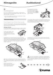
Connecting diagram<br />
T<br />
Y<br />
<strong>Truma</strong><br />
Combi<br />
...<br />
L<br />
230 V ~ N<br />
PE<br />
TP<br />
AVI<br />
R<br />
CAN CAN CAN<br />
PM PM PM<br />
A<br />
Alde<br />
Compact<br />
3010<br />
F<br />
Rs<br />
F<br />
S<br />
12 V<br />
TP <strong>Vicon</strong> 2 <strong>Touch</strong> <strong>Panel</strong><br />
PM <strong>Power</strong>modul<br />
AVI Alde-<strong>Vicon</strong>-Interface<br />
A Alde room temperature sensor<br />
CAN CAN-BUS<br />
F Fuse<br />
R Terminating resistor 120 Ω<br />
Rs Shunt<br />
Y Y-Adapter<br />
T <strong>Truma</strong> room temperature sensor<br />
Tr Toroidal transformer<br />
Ü Adapter (overload protector)<br />
Cable length and cross-section<br />
Cable Cable<br />
length<br />
...<br />
Ü<br />
Tr<br />
S5<br />
Cable<br />
cross-section<br />
W1<br />
Must be specified depending on the<br />
vehicle / configuration.<br />
CAN – 25 m ≥ 0,22 mm²<br />
Energy source connection<br />
Connect the device with the energy source (e.g. battery,<br />
generator or automatic charger). Pay attention to correct<br />
connection of the pole.<br />
Fuses must be attached near to the source of energy<br />
(e.g. battery, generator or automatic charger). Only<br />
use the stipulated cable cross-sections (see table) and fuse<br />
ratings!<br />
R<br />
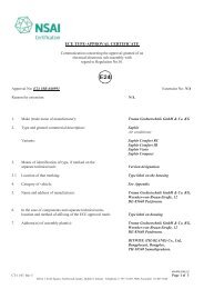
Wiring diagram 12 V voltage supply<br />
Example: 12 V voltage supply for a <strong>Power</strong> <strong>Module</strong>.<br />
+<br />
12 V<br />
+Y W1 W1<br />
Rs<br />
S<br />
F<br />
F<br />
F<br />
F<br />
12 V<br />
–<br />
S3<br />
-Y<br />
Curr. Mon.-<br />
Curr. Mon.+<br />
Batt. Comm.<br />
1 ≤ 2.2 Nm<br />
1 M 5 x 10 hexagon socket, max. torque 2.2 Nm<br />
2 Serrated washer for M5<br />
3 Washer<br />
4 12 V connection using eyelet connector (M5) max. 16 mm²<br />
F Fuse<br />
Rs Shunt<br />
S Main switch<br />
Y Y-adapter 12 V connection using eyelet connector<br />
Automatic Charger <strong>Truma</strong> BC 630 IU<br />
connection<br />
The Automatic Charger <strong>Truma</strong> BC 630 IU must be connected<br />
using a LKL adapter (part no. C30000-00500).<br />
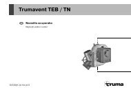
<strong>Power</strong> <strong>Module</strong> – <strong>Power</strong> <strong>Module</strong> connection<br />
The COM1 and COM2 connections can be used both as an<br />
input or output.<br />
–<br />
Connect the (PM) modules with each other. Connect<br />
the COM2 connection with the COM1 connection of the<br />
following module.<br />
–<br />
It is compulsory to connect the COM2 connector of the last<br />
module with a terminating resistor (part no. C30000-00300)<br />
PM<br />
CAN<br />
COM1<br />
COM2<br />
COM1<br />
COM2<br />
COM1<br />
COM2<br />
CAN CAN<br />
PM<br />
COM1<br />
COM2<br />
PM<br />
Strain relief for the cable is provided by the cover.<br />
4<br />
COM1<br />
COM2<br />
2<br />
3<br />
R<br />
9