Vicon 2 Power Module / Touch Panel - Truma Gerätetechnik GmbH ...
Vicon 2 Power Module / Touch Panel - Truma Gerätetechnik GmbH ...
Vicon 2 Power Module / Touch Panel - Truma Gerätetechnik GmbH ...

Sie wollen auch ein ePaper? Erhöhen Sie die Reichweite Ihrer Titel.
YUMPU macht aus Druck-PDFs automatisch weboptimierte ePaper, die Google liebt.
Installation in vehicles must accord with the technical and<br />
administrative provisions of the individual country of use (e.g.<br />
EN 1648, VDE 0100-721). The national legislation and regulations<br />
must be observed.<br />
In other countries always observe the respectively valid<br />
regulations.<br />
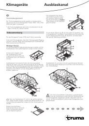
<strong>Touch</strong> <strong>Panel</strong> (TP)<br />
8<br />
Max. 1 <strong>Touch</strong> <strong>Panel</strong> can be connected per installed<br />
<strong>Vicon</strong> 2 bus system using a Y-adapter (Y).<br />
Install the <strong>Touch</strong> <strong>Panel</strong> in a place protected against moisture<br />
and wetness.<br />
– Produce an installation opening for the <strong>Touch</strong>-Display.<br />
All dimensions in mm.<br />
–<br />
–<br />
–<br />
–<br />
max. 3<br />
125<br />
148<br />
89<br />
98<br />
Plug in the cable from the Y-adapter (e.g. at plug X 1).<br />
It is compulsory that the open plug X 2 is closed off with a<br />
terminating resistor R = 120 Ω (part no. C30000-00300).<br />
A cable outlet is possible to the side or top.<br />
Insert the cable for strain relief into the cable guide.<br />
X 2<br />
X 1<br />
–<br />
–<br />
Installation instructions<br />
X 2<br />
X 1<br />
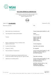
Push the cable through the installation opening and lay to<br />
the Y-adapter.<br />
Fix the <strong>Touch</strong> <strong>Panel</strong> with 4 screws (max. 3 mm outer diameter,<br />
max. torque 1 Nm).<br />
≤ 1 Nm<br />
– Press the frame onto the <strong>Touch</strong> <strong>Panel</strong> until it clicks in place.<br />
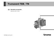
<strong>Power</strong> <strong>Module</strong> (PM)<br />
Install the <strong>Power</strong> <strong>Module</strong> in a place (wall or floor) protected<br />
against moisture and wetness.<br />
–<br />
–<br />
The <strong>Power</strong> <strong>Module</strong> must be installed in a freely accessible<br />
position without disturbing any cover elements etc.<br />
In order to allow easier servicing, <strong>Truma</strong> recommends<br />
installing a freely accessible diagnosis plug (part no.<br />
C30000-00400) in the system instead of a terminating<br />
resistor.<br />
Installation dimensions<br />
170<br />
All dimensions in mm.<br />
Removing the housing cover<br />
1<br />
Minimum installation space<br />
172<br />
1<br />
2<br />
3<br />
36.3<br />
To detach the housing cover, a suitably sized access opening<br />
must be available inside. Maintain a minimum clearance of<br />
15 mm to the housing cover if the access is closed.<br />
–<br />
Fix the device with 2 screws (no countersunk screws, max.<br />
torque 1 Nm). ´<br />
312<br />
≤ 1 Nm<br />
Ø 4,5<br />
All dimensions in mm.<br />
154.5<br />
310<br />
70<br />
52<br />
60<br />
166<br />
80