Anleitungen Drehtorantrieb HC300/HC400 ... - Chamberlain
Anleitungen Drehtorantrieb HC300/HC400 ... - Chamberlain
Anleitungen Drehtorantrieb HC300/HC400 ... - Chamberlain

Sie wollen auch ein ePaper? Erhöhen Sie die Reichweite Ihrer Titel.
YUMPU macht aus Druck-PDFs automatisch weboptimierte ePaper, die Google liebt.
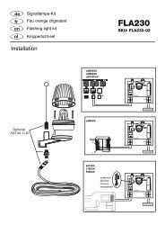
SUMMARY OF<br />
MOTOR CONTROL CONNECTIONS 14 - 18<br />
Description of connections<br />
Main supply connections:<br />
Terminal 1 L1 - 230 V (black)<br />
Terminal 2 PE (green/yellow)<br />
Terminal 3 N (blue)<br />
Warning light connections:<br />
Terminal 4 N<br />
Terminal 5 L1 (230V)<br />
Motor connections:<br />
First Motor (M1):<br />
Terminal 6 M1 actuator unit direction OPEN<br />
(+ capacitor)<br />
Terminal 7 N Blue<br />
Terminal 8 M1 actuator unit direction CLOSE<br />
(+ capacitor)<br />
Second Motor (M2):<br />
Terminal 9 M2 actuator unit direction OPEN<br />
(+ capacitor)<br />
Terminal 10 N Blue<br />
Terminal 11 M2 actuator unit direction CLOSE<br />
(+ capacitor)<br />
Gate status LED<br />
Terminal 12 LED (2 Volt)<br />
Terminal 13 LED (2 Volt)<br />
Off - gate opening<br />
On - gate closing<br />
Slow flashing - gate opening<br />
Fast flashing - gate closing<br />
Infrared light detector<br />
Terminal 14 Photocell (NC)<br />
Terminal 15 COM<br />
Terminal 16 Photocell (NC)<br />
(If the IR barrier is not used, bridge terminals<br />
14,15 and 16 must be bridged!)<br />
Description of connections<br />
Emergency-Stop-function<br />
Terminal 17 COM<br />
Terminal 18 Stop (NC) or bridge between 17 and 18<br />
Control circuit connections:<br />
Terminal 19 Outside button (NO) Motor 1 (Pedestrian function)<br />
Terminal 20 COM<br />
Terminal 21 Outside button (NO) Motor 1 + 2<br />
Auxiliary equipment connections:<br />
Terminal 22 Supply voltage 24 V AC (500 mA max.)<br />
Terminal 23 Supply voltage 24 V AC<br />
Electric lock connections:<br />
Terminal 24 Supply voltage 12 V AC<br />
Terminal 25 Supply voltage 12 V AC<br />
Antenna connections:<br />
Terminal 26 Antenna (wire)<br />
Terminal 27 Shield<br />
DESCRIPTION OF JUMPERS 15<br />
JP1: MOTOR SELECTION JUMPER<br />
OPEN: (No Jumper): Use only for single wing gates<br />
(Motor 1 operation only).<br />
CLOSED: (With Jumper): Use for double wing gates<br />
(Motor 1 and 2 operation).<br />
JP2: TWO CHANNEL RECEIVER JUMPER SELECTION<br />
OPEN: (No Jumper): Receiver channel 2 is activated.<br />
CLOSED: (With Jumper): Receiver channel 2 is not activated.<br />
GB<br />
5<br />
ANSCHLUßÜBERSICHT 14 - 18<br />
Beschreibung der Klemmenbelegung<br />
Anschluß der Zuleitung:<br />
Klemme 1 L1 - 230 V (schwarz)<br />
Klemme 2 PE (grün/gelb)<br />
Klemme 3 N (blau)<br />
Anschluß der Warnlampe:<br />
Klemme 4 N<br />
Klemme 5 L1 (230V)<br />
Anschlüsse der Motoren:<br />
Erster Motor (M1):<br />
Klemme 6 M1 Fahrtrichtung AUF<br />
(+ Kondensator)<br />
Klemme 7 N Blau<br />
Klemme 8 M1 Fahrtrichtung ZU<br />
(+ Kondensator)<br />
Zweiter Motor (M2):<br />
Klemme 9 M2 Fahrtrichtung AUF<br />
(+ Kondensator)<br />
Klemme 10 N Blau<br />
Klemme 11 M2 Fahrtrichtung ZU<br />
(+ Kondensator)<br />
Anzeige LED<br />
Klemme 12 LED (2 Volt)<br />
Klemme 13 LED (2 Volt)<br />
AUS - Tor geschlossen<br />
AN - Tor offen<br />
Blinkt langsam - Tor öffnet<br />
Blinkt schnell - Tor schließt<br />
Infrarot-Lichtschranke<br />
Klemme 14 Photozelle (NC)<br />
Klemme 15 COM<br />
Klemme 16 Photozelle (NC)<br />
(Ohne Lichtschranke - Brücke zwischen 14, 15<br />
und16!)<br />
Beschreibung der Klemmenbelegung<br />
NOTSTOP-FUNCTION<br />
Klemme 17 COM<br />
Klemme 18 Stop (NC) ohne Notstopschalter Brücke<br />
zwischen 17 und 18<br />
Anschluß der Steuerleitungen:<br />
Klemme 19 Taster extern (NO) Motor 1 (Fußgänger-Funktion)<br />
Klemme 20 COM<br />
Klemme 21 Taster extern (NO) Motor 1 + 2<br />
Anschluß für Zusatzgeräte & Lichtschranke:<br />
Klemme 22 Versorgungsspannung 24 V AC (500 mA max.)<br />
Klemme 23 Versorgungsspannung 24 V AC<br />
Anschluß für Elektroschloß:<br />
Klemme 24 Versorgungsspannung 12 V AC<br />
Klemme 25 Versorgungsspannung 12 V AC<br />
Anschluß für Antenne:<br />
Klemme 26 Antenne (Leiter)<br />
Klemme 27 Abschirmung<br />
BESCHREIBUNG DER JUMPER 15<br />
JP1: MOTOR<br />
OPEN: (ohne Jumper): Nur für einflügelige Tore<br />
(nur Motor 1 Bedienung).<br />
CLOSED: (mit Jumper): Nur für zweiflügelige Tore<br />
(Motor 1 und 2 Bedienung).<br />
JP2: FUNK (ERMÖGLICHT ÖFFNEN EINES FLÜGELS)<br />
OPEN: (ohne Jumper): Empfänger Kanal 2 wird aktiviert.<br />
CLOSED: (mit Jumper): Empfänger Kanal 2 wird nicht aktiviert.<br />
D