Anleitungen Drehtorantrieb HC300/HC400 ... - Chamberlain
Anleitungen Drehtorantrieb HC300/HC400 ... - Chamberlain
Anleitungen Drehtorantrieb HC300/HC400 ... - Chamberlain

Erfolgreiche ePaper selbst erstellen
Machen Sie aus Ihren PDF Publikationen ein blätterbares Flipbook mit unserer einzigartigen Google optimierten e-Paper Software.
D<br />
F<br />
GB<br />
NL<br />
<strong>Anleitungen</strong> <strong>Drehtorantrieb</strong> <strong>HC300</strong>/<strong>HC400</strong><br />
Drehtoröffner Steuerelektronik<br />
Instructions Automatisme portail à battants <strong>HC300</strong>/<strong>HC400</strong><br />
Automatisme portail à battants Commande électronique<br />
Instructions Swing Gate Opener <strong>HC300</strong>/<strong>HC400</strong><br />
Swing Gate Opener Logic Control Box<br />
Instrukties Vleugelpoortaandrijving <strong>HC300</strong>/<strong>HC400</strong><br />
Vleugelpoortaandrijving Besturingselektronica<br />
Für Service: (49) 6838/907-200 Pour Service: 03-87-95-39-27<br />
D F<br />
GB<br />
For Service: 0800-31-78-47 NL<br />
Voor Service: 020-684-7978
33<br />
(1) Model 704620/704621 Left-hand motor <strong>HC300</strong>/400, IP54<br />
(2) Model 704621/704623 Right-hand motor <strong>HC300</strong>/400, IP54<br />
(3) Model 704086 Post hinge elements (small, large)<br />
(4) Model 704090 Accessory package incl. Capacitor<br />
(5) Model Motor control box, IP54<br />
(6) Model 100263 Infrared barrier, IP45<br />
(7) Model 100027 1-Function Key Switch (UP - 100010)<br />
Model 100041 2-Function Key Switch (UP - 100034)<br />
(8) Model G4330EML 1-Function Remote Control (433MHz)<br />
(9) Model G4333EML 3-Function Remote Control (433MHz)<br />
(10) Model G4335EML 3-Function Mini Remote Control (433MHz)<br />
(11) Model G747EML Wireless Keyless Entry Keypad (433MHz)<br />
(12) Model RXCA-433 Receiver (433MHz)<br />
(13) Model G760EML Outside Keylock<br />
(14) Model 100287 Flashing Light Kit<br />
GB<br />
(1) Modell 704620/704621 Motor links <strong>HC300</strong>/400, IP54<br />
(2) Modell 704621/704623 Motor rechts <strong>HC300</strong>/400, IP54<br />
(3) Modell 704086 Scharnierteile zur Befestigung (klein, groß)<br />
(4) Modell 704090 Zubehörbeutel inkl. Kondensator<br />
(5) Modell Steuerung, IP54<br />
(6) Modell 100263 Sicherheitslichtschranke, IP45<br />
(7) Modell 100027 1-B Schlüsselschalter (UP - 100010)<br />
Modell 100041 2-B Schlüsselschalter (UP - 100034)<br />
(8) Modell G4330EML 1-Befehl Fernbedienung (433MHz)<br />
(9) Modell G4333EML 3-Befehl Fernbedienung (433MHz)<br />
(10) Modell G4335EML 3-Befehl Fernbedienung Mini (433MHz)<br />
(11) Modell G747EML Drahtloser Digitaltaster (433MHz)<br />
(12) Modell RXCA-433 Empfänger (433MHz)<br />
(13) Modell G760EML Schlüsselschalter außen<br />
(14) Modell 100287 Blinkleuchte<br />
1 2 3<br />
5 6 7<br />
10 11 12<br />
D<br />
(1) Model 704620/704621 Moteur à gauche <strong>HC300</strong>/400, IP54<br />
(2) Model 704621/704623 Moteur à droite <strong>HC300</strong>/400, IP54<br />
(3) Model 704086 Charnières de fixation<br />
(4) Model 704090 Sachet d’accessoires incl. Condensateur<br />
(5) Model Commande électronique, IP54<br />
(6) Model 100263 Jeu de cellules, IP45<br />
(7) Model 100027 Contacteur à clé 1 ordre (à encastrer - 100010)<br />
Model 100041 Contacteur à clé 2 ordres (à encastrer - 100034)<br />
(8) Model G4330EML Télécommande 1-fonction (433MHz)<br />
(9) Model G4333EML Télécommande 3-fonctions (433MHz)<br />
(10) Model G4335EML Télécommande 3-fonctions mini (433MHz)<br />
(11) Model G747EML Clavier numérique d’entrée<br />
sans clé sans fil (433MHz)<br />
(12) Model RXCA-433 Télécommande radio (433MHz)<br />
(13) Model G760EML Contacteur à clé<br />
(14) Model 100287 Feu orange clignotantt<br />
F<br />
(1) Model 704620/704621 Motorunit links <strong>HC300</strong>/400, IP54<br />
(2) Model 704621/704623 Motorunit rechts <strong>HC300</strong>/400, IP54<br />
(3) Model 704086 Scharnieronderdelen voor bevestiging<br />
(4) Model 704090 Zakje met toebehoren incl. Condensator<br />
(5) Model Besturingselektronica, IP54<br />
(6) Model 100263 Beveiligingssysteem, IP45<br />
(7) Model 100027 1-F Sleutelschakelaar buiten (UP - 100010)<br />
Model 100041 2-F Sleutelschakelaar buiten (UP - 100034)<br />
(8) Model G4330EML 1-kanaal afstandsbediening (433MHz)<br />
(9) Model G4333EML 3-kanaals afstandsbediening (433MHz)<br />
(10) Model G4335EML Mini-afstandsbediening<br />
met 3 functies (433MHz)<br />
(11) Model G747EML Draadloos pincodeslot<br />
zonder sleutel (433MHz)<br />
(12) Model RXCA-433 Radiografische afstandsbediening (433MHz)<br />
(13) Model G760EML Sleutelschakelaar buiten<br />
(14) Model 100287 Knipperlicht - set<br />
NL<br />
© 1998<br />
709093B All rights reserved Printed in the EU<br />
13<br />
4<br />
8 9<br />
14
START BY READING THESE IMPORTANT SAFETY<br />
RULES<br />
These safety alert symbols mean Caution – a<br />
personal safety or property damage instruction.<br />
Read these instructions carefully.<br />
This gate opener is designed and tested to offer<br />
reasonable safe service provided it is installed<br />
and operated in strict accordance with the<br />
following safety rules.<br />
Failure to comply with the following instructions may<br />
result in serious personal injury or property damage.<br />
Keep gate balanced. Sticking or binding gates must<br />
be repaired. Do not attempt to repair the gates<br />
yourself. Call for service.<br />
Handle tools and hardware carefully and do not<br />
wear rings, watches or loose clothing while<br />
installing or servicing a gate opener.<br />
Installation and wiring must be in compliance with<br />
your local building and electrical codes. Connect the<br />
power cord only to properly earthed mains.<br />
Ensure that persons who install, maintain or<br />
operate the gate opener follow these instructions.<br />
Keep this manual where it can be readily referenced<br />
during maintenance.<br />
Disengage all existing gate locks to avoid damage<br />
to gate opener.<br />
CAUTION: Activate opener only when the gate is<br />
in full view, free of obstructions and opener is<br />
properly adjusted. Do not allow children to play<br />
near the gate.<br />
Disconnect electric power to the gate opener<br />
before making repairs.<br />
Keep additional accessories out of the reach of<br />
children. Do not allow children to operate push<br />
button(s) or remote control(s). Serious personal<br />
injury from a closing gate may result from misuse of<br />
the opener.<br />
Contents:<br />
Safety Rules: Page 1<br />
Contents of the carton: Page 2, Illustration 1<br />
Product description: Page 2 Illustrations 2 - 3<br />
Technical data: Page 2<br />
Installation: Pages 2-3, Illustrations 4 - 6<br />
Intallation of Wing Gate Actuator Unit:<br />
Page 3, Illustrations 7 - 12<br />
Instruction Manual Logic Control Box: Page 4<br />
Technical Features: Page 4<br />
Electrical Installation: Page 4, Illustration 13<br />
Summary of Motor Control Connections:<br />
Pages 5-6, Illustrations 14 - 18<br />
Installation of Accessories: Page6- Illustrations 19 - 31<br />
Initial Setting of Motor Control System: Page 7<br />
Initial Setting of Remote Control: Page 7, Illustration 32<br />
Warranty: Page 8<br />
Accessories: Page 12, Illustration 33<br />
GB<br />
1<br />
BEGINNEN SIE MIT LESEN DIESER WICHTIGEN<br />
SICHERHEITSREGELN<br />
Solche Warnzeichen bedeuten “Vorsicht!”, eine<br />
Aufforderung zur Beachtung, da ihre Mißachtung<br />
Personen- bzw. Sachschäden verursachen kann.<br />
Bitte lesen Sie diese Warnungen sorgfältig.<br />
Dieser Toröffner ist so konstruiert und geprüft,<br />
daß er bei Installation und Benutzung unter<br />
genauer Befolgung der anschließenden<br />
Sicherheitsregeln angemessene Sicherheit bietet.<br />
Die Nichtbeachtung der folgenden Sicherheitsregeln kann<br />
ernsthafte Personen- oder Sachschäden verursachen.<br />
Es ist wichtig, das Tor immer gut gangbar zu<br />
halten. Tore die steckenbleiben oder verklemmen,<br />
sind unverzüglich zu reparieren.Versuchen Sie<br />
nicht das Tor selbst zu reparieren. Bestellen Sie<br />
dafür einen Fachmann.<br />
Beim Umgang mit Werkzeugen und Kleinteilen<br />
Vorsicht walten lassen und weder Ringe, Uhren<br />
noch lose Kleidungsstücke tragen, wenn Sie<br />
Installations- oder Reparaturarbeiten an einem Tor<br />
vornehmen.<br />
Elektrische Leitungen sind entsprechend den lokalen<br />
Bau- und Elektroinstallationsvorschriften zu verlegen. Das<br />
elektrische Kabel darf nur an ein ordnungsgemäß<br />
geerdetes Netz angeschlossen werden.<br />
Stellen Sie sicher, daß Personen, die den Antrieb<br />
montieren, warten oder bedienen diesen<br />
<strong>Anleitungen</strong> folgen.<br />
Bewahren Sie die Anleitung an einem Ort auf, an<br />
dem schnell auf sie zurückgegriffen werden kann.<br />
Enffernen Sie bitte alle am Tor angebrachten<br />
Schlösser um Schaden am Tor zu vermeiden.<br />
VORSICHT! Betätigen Sie den Öffner nur, wenn Sie<br />
das Tor voll im Blickfeld haben, sich dort keine<br />
behindernden Gegenstände befinden und der<br />
Öffner richtig eingestellt ist. Kinder sollten nicht in<br />
Tornähe bei Betätigung des Öffners spielen.<br />
Unterbrechen Sie den Storm zum Torantrieb bevor<br />
Sie Reparaturen machen.<br />
Entfernen Sie zusätzliches Zubehör aus der Nähe<br />
von Kindern. Erlauben Sie Kindern nicht<br />
Drucktaster und Fernbedienungen zu bedienen.<br />
Schwere Verletzungen können durch ein sich<br />
schließendes Tor verursacht werden.<br />
Inhalt:<br />
Sicherheitsregeln: Seite 1<br />
Inhalt des Kartons: Seite 2, Abbildung 1<br />
Produktbeschreibung: Seite 2, Abbildungen 2 - 3<br />
Technische Daten: Seite 2<br />
Montage: Seite 2-3, Abbildungen 4 - 6<br />
Einbau des <strong>Drehtorantrieb</strong>es: Seite 3,Abbildungen 7 - 12<br />
Montageanleitung Elektronik: Seite 4<br />
Technische Eigenschaften: Seite 4<br />
Elektrische Installation: Seite 4, Abbildung 13<br />
Anschlußübersicht: Seite 5-6, Abbildungen 14 - 18<br />
Installation von Zubehör: Seite 6, Abbildungen 19 - 31<br />
Grundeinstellung: Seite 7<br />
Einstellung der Fernbedienung: Seite7, Abbildung 32<br />
Garantie: Seite 8<br />
Zubehör: Seite 12, Abbildung 33<br />
D
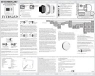
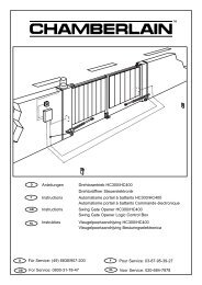
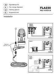
CONTENTS OF THE CARTON<br />
(1) Wing gate actuator unit for left-hand installation and/or<br />
(2) Wing gate actuator unit for right-hand installation<br />
(3) Mounting brackets<br />
(4) Installation accessories pack<br />
Hinge pins with circlips (2)<br />
Emergency opening handle (1)<br />
Capacitor (1)<br />
(5) Instruction manual<br />
(6) Warning light kit<br />
(7) IR Sensors<br />
(8) Transmitter<br />
(9) Control box<br />
PRODUCT DESCRIPTION 2 - 3 PRODUKTBESCHREIBUNG 2 - 3<br />
<strong>HC300</strong>R, <strong>HC300</strong>L, <strong>HC400</strong>R+L<br />
Scope of application: Motorized opening and closing of<br />
gates.<br />
Illustration 3 shows a dimensional outline of the actuator arms.<br />
The actuator units are suitable for use with single and double<br />
gates. For <strong>HC300</strong>, the maximum gate width may not exceed<br />
2.5 m and for <strong>HC400</strong> it may not exceed 3.0 m. Maximum<br />
weight 300 kg per gate.<br />
For design reasons, all wing gate actuator units, operating<br />
with linear movement, must follow the given installation<br />
dimensions. Some gate or post types may require recessing<br />
of the post or use of the longer stroke actuator, in order to<br />
achieve the installation dimensions.<br />
Technical data<br />
<strong>HC300</strong> <strong>HC400</strong><br />
Power supply 230V - 50Hz 230V - 50Hz<br />
Capacitor 10 µF 10 µF<br />
Current drawn 1.5 A 1.5 A<br />
Power 350W 350W<br />
Opening angle 110° max 110° max<br />
Max. cycles/hours 20 20<br />
Force 200kg 200kg<br />
Max. actuator unit length 97cm 112cm<br />
Motor thermal overload switch 140 °C 140 °C<br />
Rated weight of motor 6.5kg 7kg<br />
Dimensions see fig.3 see fig.3<br />
Speed 1.5cm/s 1.5cm/s<br />
IP Rating (motor) IP54 IP54<br />
INSTALLATION -<br />
Preparations<br />
Before installation, please check contents of packaging.<br />
Please refer to Illustration 1.<br />
Ensure your gate equipment functions correctly.<br />
Please keep in mind, that you will need parts not included in<br />
the packaging (tubes, cable, screws, rawlplug and so on)<br />
Installation preparation<br />
As an example, Illustration 4 illustrates installation with a<br />
stone or steel post construction. The installation dimensions<br />
for the gate actuator unit are dependant on the fastening<br />
points of gate to post.<br />
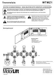
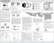
llustration 5 shows the meaning of installation dimensions A<br />
and B. The measurements chosen also determine the opening<br />
and closing times and the maximum opening angle of the gate.<br />
Sample for A=14cm and B=14cm (approx. 900 4 6<br />
)<br />
GB<br />
1 INHALT DES KARTONS<br />
2<br />
(1) <strong>Drehtorantrieb</strong> für Linkseinbau und/oder<br />
(2) <strong>Drehtorantrieb</strong> für Rechtseinbau<br />
(3) Scharnierteile zur Befestigung<br />
(4) Montagezubehörbeutel<br />
Befestigungsbolzen mit Sicherheitsringen (2)<br />
Notentriegelung (1)<br />
Kondensator (1)<br />
(5) Montageanleitung<br />
(6) Warnlampe<br />
(7) Sicherheitslichtschranke<br />
(8) Handsender<br />
(9) Steuerung<br />
<strong>HC300</strong>R, <strong>HC300</strong>L, <strong>HC400</strong>R+L<br />
Bestimmungsgemäßer Gebrauch: Motorisiertes Öffnen und<br />
Schließen von Toren.<br />
Abbildung 3 zeigt die Abmessungen der Antriebe.<br />
Die Antriebe sind für ein -und zweiflügelige Tore geeignet Die<br />
Breite eines Torflügels darf beim <strong>HC300</strong> nicht über 2,5 m,<br />
beim <strong>HC400</strong> nicht über 3,0 m betragen. Maximales Gewicht<br />
300kg pro Flügel.<br />
Bauartbedingt müssen bei allen <strong>Drehtorantrieb</strong>en, die mit<br />
linearer Bewegung arbeiten, bestimmte Einbaumaße<br />
eingeghalten werden. Je nach Beschaffenheit des Pfeilers<br />
oder Torflügels können diese Maße nur durch Ausparungen<br />
am Pfeiler oder durch Verwendung von Antrieben mit<br />
größerem Hub erreicht werden.<br />
Technische Daten<br />
<strong>HC300</strong> <strong>HC400</strong><br />
Netzanschluß 230V - 50Hz 230V - 50Hz<br />
Kondensator 10 µF 10 µF<br />
Stromaufnahme 1.5 A 1.5 A<br />
Leistungsaufnahme 350W 350W<br />
Öffnungswinkel 110° max 110° max<br />
Max. Zyklen/Std. 20 20<br />
Zugkraft 200kg 200kg<br />
Max. Antriebslänge 97cm 112cm<br />
Motorthermoschutz 140 °C 140 °C<br />
Nettogewicht Motor 6.5kg 7kg<br />
Abmessungen siehe Abb..3 siehe Abb..3<br />
Geschwindigkeit 1.5cm/s 1.5cm/s<br />
IP Werte (Motor) IP54 IP54<br />
1<br />
MONTAGE -<br />
Vorbereitungen<br />
Überprüfen Sie bitte vor der Montage den Inhalt der<br />
Verpackung auf Vollständigkeit. Siehe Abbildung 1.<br />
Stellen Sie die einwandfreie Arbeitsweise Ihrer Torvorrichtung<br />
sicher. Bedenken Sie, daß Sie noch Material benötigen, daß<br />
sich verständlicherweise nicht in unserem Lieferumfang<br />
befinden kann (Leerrohr, Kabel, Schrauben, Dübel etc.)<br />
Montagevorbereitungen<br />
Beispiele für eine Montage an Mauerwerk oder Stahlpfeilern<br />
sind in Abb. 4 dargestellt. Die Montagemaße eines Torantriebes<br />
sind von der Befestigung des Torflügels am Pfeiler abhängig.<br />
Abb. 5 zeigt die Bedeutung der Einbaumaße A und B. Die<br />
gewählten Maße bestimmen gleichzeitig die Öffnungs- und<br />
Schließzeit und den maximalen Öffungswinkel eines Torflügels.<br />
Beispiel für A=14cm und B=14cm (für ca. 900 4 6<br />
)<br />
D
As a rule:<br />
B greater than A slower, smoother closing, gate<br />
opens faster.<br />
A greater than B greater opening angle, however, when<br />
closing, the gate makes a harder and<br />
faster contact with the post stop.<br />
For an opening angle of 90°, addition of the dimensions A<br />
and B always gives the total actuator stroke. When a gate<br />
opening angle greater than 90° is required, dimension B will<br />
need to be reduced accordingly.<br />
In order to obtain the optimum dimensions, it may be<br />
necessary to shorten or lengthen the hinge plates supplied.<br />
In the case of a new gate, dimensions A and B may be<br />
changed when the gate angle brackets are fastened to the<br />
post accordingly. Before the installation dimensions are<br />
finalised, ensure that the gate actuator unit does not touch<br />
the post when moving.<br />
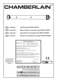
Please refer to Illustration 6 - Table. (If only one value is<br />
stated: value for <strong>HC300</strong>/<strong>HC400</strong> identical.)<br />
To avoid undesirable jerking movement, the gate should be<br />
stable and the angle brackets should have as little play as<br />
possible. The easier the gate movement, the finer the torque<br />
adjustment. Fragile wooden gates should be reinforced with<br />
a metal frame.<br />
INSTALLATION OF WING GATE<br />
ACTUATOR UNIT 7 - 12<br />
(1) Fasten the hinge elements to the gate and post in<br />
accordance with the installation dimensions calculated<br />
beforehand. The smaller element is to be fitted to the gate<br />
and the larger fitted to the post (Illustration 7).<br />
NOTE: The hinge elements must be vertically aligned to<br />
one another<br />
The force which the actuator unit applies against the post is<br />
considerable. A steel post is the most suitable from the<br />
stability point of view. Quite acceptable installation<br />
dimensions are usually obtained when the hinge plates<br />
supplied are welded directly onto the post.<br />
In the case of thick stone or concrete posts, the hinge<br />
element must be welded onto a support plate and then<br />
fastened in such a way that the dowels cannot become loose<br />
during operation. For this purpose, glued shear connectors, in<br />
which a threaded rod is inserted into the wall without pressure,<br />
are more suitable than steel or plastic expansion dowels.<br />
In the case of brick walls, a large steel plate, covering<br />
several bricks, should be screwed onto the wall and the hinge<br />
plate welded onto this base plate. An angle iron over the<br />
corner of a post is also a suitable fastening support.<br />
(2) Place a water-tight junction box next to the hinge plate on<br />
the post. The Wing gate motor supply cable is led into this<br />
box from below (Illustration 8).<br />
(3) Using the hexagonal handle supplied, release the actuator<br />
unit by loosening the emergency release screw a half-turn in the<br />
clockwise direction. Then extend the actuator to its maximum<br />
length. Re-tighten the actuator unit by turning the screw a halfturn<br />
in the anticlockwise direction (Illustrations 9 and 10).<br />
With the gate closed, slide the fully extended actuator onto<br />
the hinge element and fasten it using the hinge pins supplied<br />
in the accessories pack. The hinge pins are blocked using<br />
the circlips which are inserted into the bottom groove of the<br />
hinge pins (Illustrations 11 and 12).<br />
GB<br />
3<br />
Grundsätzlich gilt:<br />
B größer als A langsameres, sanftes Schließen, Flügel<br />
wird beim Öffnen schneller<br />
A größer als B großer Öffnungswinkel, Flügel fährt aber<br />
beim Schließen schnell und hart an den<br />
Pfeileranschlag an<br />
Für einen Öffnungswinkel von 90° ergibt die Addition der<br />
Maße A und B immer den gesamten Kolbenhub. Soll der<br />
Torflügel weiter als 90° aufgehen, muß das Maß B<br />
entsprechend verkleinert werden.<br />
Um optimale Maße zu erreichen, kann es nötig sein, die<br />
mitgelieferte Scharnierplatte zu kürzen oder zu verlängern.<br />
Bei neu anzufertigenden Toren kann, wenn die Torangeln an<br />
den Pfeilern entsprechend montiert werden, Einfluß auf die<br />
Maße A und B genommen werden. Bevor die Anbaumaße<br />
endgültig festgelegt werden, sollte immer geprüft werden, ob<br />
der Antrieb beim Schwenken nicht am Pfeiler anecken könnte.<br />
Siehe Abb. 6 - Beispeiltabelle. (Bei Angabe nur eines<br />
Meßwertes: Meßwert für <strong>HC300</strong>/<strong>HC400</strong> identisch.)<br />
Um störende Pendelbewegungen zu vermeiden sollte der<br />
Flügel stabil und die Torangeln möglichst spielfrei sein. Je<br />
leichtgängiger der Flügel, desto feinfühliger ist die Kraft<br />
einzustellen. Labile Holztore sollten mit einem Metallrahmen<br />
verstärkt werden.<br />
MONTAGE DES DREHTORANTRIEBES 7 - 12<br />
(1) Bringen Sie gemäß den zuvor ermittelten Einbaumaßen<br />
die Scharnierteile an Torflügel und Pfeiler an. Das kleinere<br />
Teil ist für den Torflügel vorgesehen, das größere für den<br />
Pfeiler (Abb. 7).<br />
ANNMERKUNG: Die Scharnierteile müssen zueinander<br />
waagerecht ausgerichtet sein.<br />
Die Kräfte, mit denen sich der Antrieb gegen den Pfeiler<br />
abstützt, sind sehr groß. Ein Stahlpfeiler bereitet von der<br />
Stabilität her die wenigsten Probleme. Meistens ergeben sich<br />
schon akzeptable Einbaumaße, wenn die mitgelieferte<br />
Scharnierplatte direkt an den Pfeiler geschweißt wird.<br />
Bei dicken Stein- oder Betonpfosten muß das Scharnierteil<br />
auf eine Trägerplatte geschweißt und so befestigt werden,<br />
daß sich die Dübel im Betrieb nicht lockern können. Besser<br />
als Stahl- oder Kunststoff-Spreizdübel eignen sich hierzu<br />
Klebe-Verbundanker, bei denen ein Gewindestift Spannungsfrei<br />
im Mauerwerk eingeklebt wird.<br />
Bei gemauerten Pfeilern sollte eine größere Stahlplatte,<br />
mehrere Steine überdeckend, angeschraubt werden, auf die<br />
dann die Scharnierplatte aufgeschweißt werden kann. Gut<br />
zur Befestigung eignet sich auch eine um die Pfeilerkante<br />
befestigte Winkelplatte.<br />
(2) Setzen Sie neben die Scharnierplatte am Pfeiler eine<br />
wasserdichte Verteilerdose. Hier wird das Anschlußkabel des<br />
<strong>Drehtorantrieb</strong>es von unten eingeführt (Abb. 8).<br />
(3) Entriegeln Sie den Antrieb, indem Sie die<br />
Notentriegelungsschraube mit dem mitgelieferten<br />
Sechskantschlüssel um eine halbe Drehung im Uhrzeigersinn<br />
drehen. Ziehen Sie dann den Kolben auf fast maximale Länge<br />
heraus. Verriegeln Sie anschließend den Antrieb wieder durch<br />
eine halbe Drehung im Gegenuhrzeigersinn (Abb. 9 und 10).<br />
Schieben Sie anschließend bei geschlossenem Torflügel den auf<br />
maximal zulässige Länge ausgezogenen Antrieb auf die<br />
Scharnierteile auf und befestigen Sie ihn mit Hilfe der im<br />
Zubehörbeutel enthaltenen Bolzen. Die Bolzen werden durch<br />
die auf die untere Bolzennut aufzuschiebenden Sicherheitsringe<br />
gesichert (Abb. 11 und 12).<br />
D
3<br />
1<br />
1<br />
2<br />
5<br />
<strong>HC300</strong>: 62 cm<br />
<strong>HC400</strong>: 72 cm<br />
6<br />
2<br />
4<br />
A<br />
8 10 12 14 16 18 20 22 24<br />
8 100 0 110 0 120 0 125 0 110 0 /131 0 100 0 /115 0 93 0 /120 0 88 0 /109 0 84 0 /102 0<br />
10 99 0 108 0 115 0 121 0 101 0 /125 0 93 0 /128 0 89 0 /113 0 83 0 /104 0<br />
B 12 95 0 105 0 110 0 105 0 /118 0 93 0 /122 0 86 0 /118 0 82 0 /105 0<br />
14 95 0 100 0 108 0 95 0 /115 0 87 0 /118 0<br />
16 94 0 100 0 106 0 93 0 /110 0<br />
18 97 0 97 0<br />
20 91 0<br />
5 CHAMBERLAIN<br />
8<br />
INSTRUCTION MANUAL<br />
2.5m Swing Gate Opener - <strong>HC300</strong><br />
3.0m Swing Gate Opener - Hc400<br />
<strong>Chamberlain</strong><br />
Alfred-Nobel-Str. 4<br />
D-66793 Saarwelligen<br />
(49) 6838/907-200<br />
<strong>HC300</strong>: 92 cm / <strong>HC400</strong>: 110 cm<br />
3<br />
6 7<br />
9<br />
9<br />
4
7 8<br />
10<br />
13<br />
15<br />
21<br />
L6<br />
18<br />
L5 L4 L3 L2 L1<br />
2 6 7 8<br />
schwarz, noir<br />
blau, bleu<br />
braun, marron<br />
gelb/grün, jaune/vert<br />
11<br />
Capacitor/Kondensator/<br />
Condensateur<br />
black<br />
1<br />
blue<br />
2<br />
3 brown<br />
yellow/green<br />
4<br />
19<br />
16<br />
JP1<br />
• • •<br />
14<br />
L1 PE N<br />
230V 230V<br />
Earth/Erdung/<br />
1 2 3 4 5 6 7 8 9 10 11<br />
10<br />
JP2<br />
22<br />
-<br />
9<br />
12<br />
+<br />
12 13 14 15 16 17 18 19 20 21 22 23 24 25 26 27<br />
20<br />
Capacitor/Kondensator/<br />
Condensateur<br />
black<br />
17<br />
schwarz, noir<br />
1<br />
blue 2 blau, bleu<br />
brown 3 braun, marron<br />
yellow/green<br />
4<br />
gelb/grün, jaune/vert<br />
2 6 7 8
23 24<br />
25<br />
27<br />
-<br />
-<br />
2 Capacitor/Kondensator/<br />
Condensateur<br />
brown/braun/<br />
marron<br />
+<br />
12 13<br />
+<br />
12 13<br />
6 7 8 9 10 11<br />
1 2 3 4 1 2 3 4<br />
blue/blau/bleu<br />
black/schwarz/<br />
noir<br />
yellow/green,<br />
gelb/grün,<br />
jaune/vert<br />
Capacitor/Kondensator/<br />
Condensateur<br />
black/schwarz/<br />
noir<br />
blue/blau/bleu<br />
brown/braun/<br />
marron<br />
Left Right<br />
yellow/green,<br />
gelb/grün,<br />
jaune/vert<br />
14 15 16 17 18 19 20 21 22 23 24 25 26 27<br />
14 15 16 17 18 19 20 21 22 23 24 25 26 27<br />
➔<br />
SWITCH<br />
31 32<br />
22 23 24 25 26 27<br />
10-15m<br />
75 Ω<br />
28<br />
17 18 19 20 21 22 23<br />
11<br />
➔<br />
SWITCH<br />
26<br />
2 Capacitor/Kondensator/<br />
Condensateur<br />
brown/braun/<br />
marron<br />
6 7 8 9 10 11<br />
Capacitor/Kondensator/<br />
Condensateur<br />
1 2 3 4 1 2 3 4<br />
blue/blau/bleu<br />
black/schwarz/<br />
noir<br />
yellow/green,<br />
gelb/grün,<br />
jaune/vert<br />
black/schwarz/<br />
noir<br />
blue/blau/bleu<br />
brown/braun/<br />
marron<br />
yellow/green,<br />
gelb/grün,<br />
jaune/vert<br />
Left Right<br />
29<br />
17 18 19 20 21 22 23<br />
➔<br />
SWITCH<br />
14 15 16 17 18 1920 21 22 23<br />
1<br />
30<br />
22 23 24 25 26 27<br />
2
TECHNICAL FEATURES<br />
Power supply 230V-50Hz<br />
Absorbed power 10W<br />
Max. motor load 700W<br />
Max. load on accessories 0.9A<br />
Auxilliary output 24V AC<br />
Protection fuses 4<br />
Operating logic Step by step/Automatic<br />
Housing Dimensions 90x195x250mm<br />
Housing drgree ofProtection IP54<br />
ELECTRICAL INSTALLATION<br />
The electronic control unit supplied is required for operation<br />
of the wing gate actuator. This control unit comprises an<br />
electronic microprocessor-control system employing the latest<br />
technology. It may be used for the connection of 1 or 2<br />
motors and offers all connection possibilities and functions<br />
necessary for safe and reliable operation.<br />
The electrical connections for single- or double gates are<br />
given in Illustration 13.<br />
The control box containing the motor control module is to be<br />
fitted with cable entry at bottom. It should not be continuously<br />
exposed to direct sunlight. For weather protection, we<br />
recommend the fitting of a small protection roof.<br />
Thanks to the electronic control unit, fine adjustment of the<br />
push-pull torque is possible. When correctly adjusted, gate<br />
movement can be easily blocked by hand.<br />
For the OPEN and CLOSED positions, the gate requires a<br />
stable end stop as the swing gate actuator unit is not<br />
fitted with limit switches and the electronic controls are<br />
switched off by time.<br />
GB<br />
13<br />
4<br />
TECHNISCHE EIGENSCHAFTEN<br />
Netzanschluß 230V-50HzHz<br />
Stromverbrauch 10W<br />
Max.Motorbelastung 700W<br />
Max. Belastung Zubehör 0.9A<br />
Max. Belastung E-Schloß 24V AC<br />
Sicherungen 4<br />
Betriebslogik Schritt für Schritt/Automatik<br />
Abmessungen 90x195x250mm<br />
Schutz IP54<br />
ELEKTRISCHE INSTALLATION<br />
Zum Betrieb des <strong>Drehtorantrieb</strong>s ist die mitgelieferte<br />
elektronische Steuerung erforderlich. Bei dieser Motorsteuerung<br />
handelt es sich um eine mikroprozessorgesteuerte Elektronik<br />
mit modernster Technik. Sie ist für den Anschluß von bis zu 2<br />
Motoren geeignet und hat alle für den sicheren Betrieb<br />
notwendigen Anschlußmöglichkeiten und Funktionen.<br />
Der elektrische Anschluß ist für Einflügel- und Zweiflügel-Tore in<br />
einer Übersicht in Abb. 13 dargestellt.<br />
Die Steuerbox mit der Motorsteuerung ist mit den<br />
Kabeldurchführungen nach unten zu montieren. Sie darf<br />
direkter Sonneneinstrahlung nicht dauernd ausgesetzt sein. Es<br />
empfiehlt sich, als Schutz vor Regen ein kleines Schutzdach zu<br />
montieren.<br />
Das Tor läßt sich bei richtiger Einstellung von Hand<br />
festhalten.<br />
Während des Laufes kann das Tor jederzeit über Funk, Taster<br />
oder Schlüsselschalter gestoppt werden.<br />
Der Torflügel benötigt für "AUF-" und "ZU"-Stellung<br />
einen stabilen Anschlag, da die <strong>Drehtorantrieb</strong>e keine<br />
Endschalter besitzen und die Abschaltung der Elektronik<br />
über die Zeit erfolgt.<br />
13<br />
D
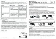
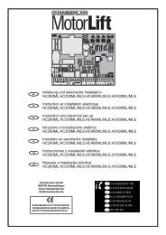
SUMMARY OF<br />
MOTOR CONTROL CONNECTIONS 14 - 18<br />
Description of connections<br />
Main supply connections:<br />
Terminal 1 L1 - 230 V (black)<br />
Terminal 2 PE (green/yellow)<br />
Terminal 3 N (blue)<br />
Warning light connections:<br />
Terminal 4 N<br />
Terminal 5 L1 (230V)<br />
Motor connections:<br />
First Motor (M1):<br />
Terminal 6 M1 actuator unit direction OPEN<br />
(+ capacitor)<br />
Terminal 7 N Blue<br />
Terminal 8 M1 actuator unit direction CLOSE<br />
(+ capacitor)<br />
Second Motor (M2):<br />
Terminal 9 M2 actuator unit direction OPEN<br />
(+ capacitor)<br />
Terminal 10 N Blue<br />
Terminal 11 M2 actuator unit direction CLOSE<br />
(+ capacitor)<br />
Gate status LED<br />
Terminal 12 LED (2 Volt)<br />
Terminal 13 LED (2 Volt)<br />
Off - gate opening<br />
On - gate closing<br />
Slow flashing - gate opening<br />
Fast flashing - gate closing<br />
Infrared light detector<br />
Terminal 14 Photocell (NC)<br />
Terminal 15 COM<br />
Terminal 16 Photocell (NC)<br />
(If the IR barrier is not used, bridge terminals<br />
14,15 and 16 must be bridged!)<br />
Description of connections<br />
Emergency-Stop-function<br />
Terminal 17 COM<br />
Terminal 18 Stop (NC) or bridge between 17 and 18<br />
Control circuit connections:<br />
Terminal 19 Outside button (NO) Motor 1 (Pedestrian function)<br />
Terminal 20 COM<br />
Terminal 21 Outside button (NO) Motor 1 + 2<br />
Auxiliary equipment connections:<br />
Terminal 22 Supply voltage 24 V AC (500 mA max.)<br />
Terminal 23 Supply voltage 24 V AC<br />
Electric lock connections:<br />
Terminal 24 Supply voltage 12 V AC<br />
Terminal 25 Supply voltage 12 V AC<br />
Antenna connections:<br />
Terminal 26 Antenna (wire)<br />
Terminal 27 Shield<br />
DESCRIPTION OF JUMPERS 15<br />
JP1: MOTOR SELECTION JUMPER<br />
OPEN: (No Jumper): Use only for single wing gates<br />
(Motor 1 operation only).<br />
CLOSED: (With Jumper): Use for double wing gates<br />
(Motor 1 and 2 operation).<br />
JP2: TWO CHANNEL RECEIVER JUMPER SELECTION<br />
OPEN: (No Jumper): Receiver channel 2 is activated.<br />
CLOSED: (With Jumper): Receiver channel 2 is not activated.<br />
GB<br />
5<br />
ANSCHLUßÜBERSICHT 14 - 18<br />
Beschreibung der Klemmenbelegung<br />
Anschluß der Zuleitung:<br />
Klemme 1 L1 - 230 V (schwarz)<br />
Klemme 2 PE (grün/gelb)<br />
Klemme 3 N (blau)<br />
Anschluß der Warnlampe:<br />
Klemme 4 N<br />
Klemme 5 L1 (230V)<br />
Anschlüsse der Motoren:<br />
Erster Motor (M1):<br />
Klemme 6 M1 Fahrtrichtung AUF<br />
(+ Kondensator)<br />
Klemme 7 N Blau<br />
Klemme 8 M1 Fahrtrichtung ZU<br />
(+ Kondensator)<br />
Zweiter Motor (M2):<br />
Klemme 9 M2 Fahrtrichtung AUF<br />
(+ Kondensator)<br />
Klemme 10 N Blau<br />
Klemme 11 M2 Fahrtrichtung ZU<br />
(+ Kondensator)<br />
Anzeige LED<br />
Klemme 12 LED (2 Volt)<br />
Klemme 13 LED (2 Volt)<br />
AUS - Tor geschlossen<br />
AN - Tor offen<br />
Blinkt langsam - Tor öffnet<br />
Blinkt schnell - Tor schließt<br />
Infrarot-Lichtschranke<br />
Klemme 14 Photozelle (NC)<br />
Klemme 15 COM<br />
Klemme 16 Photozelle (NC)<br />
(Ohne Lichtschranke - Brücke zwischen 14, 15<br />
und16!)<br />
Beschreibung der Klemmenbelegung<br />
NOTSTOP-FUNCTION<br />
Klemme 17 COM<br />
Klemme 18 Stop (NC) ohne Notstopschalter Brücke<br />
zwischen 17 und 18<br />
Anschluß der Steuerleitungen:<br />
Klemme 19 Taster extern (NO) Motor 1 (Fußgänger-Funktion)<br />
Klemme 20 COM<br />
Klemme 21 Taster extern (NO) Motor 1 + 2<br />
Anschluß für Zusatzgeräte & Lichtschranke:<br />
Klemme 22 Versorgungsspannung 24 V AC (500 mA max.)<br />
Klemme 23 Versorgungsspannung 24 V AC<br />
Anschluß für Elektroschloß:<br />
Klemme 24 Versorgungsspannung 12 V AC<br />
Klemme 25 Versorgungsspannung 12 V AC<br />
Anschluß für Antenne:<br />
Klemme 26 Antenne (Leiter)<br />
Klemme 27 Abschirmung<br />
BESCHREIBUNG DER JUMPER 15<br />
JP1: MOTOR<br />
OPEN: (ohne Jumper): Nur für einflügelige Tore<br />
(nur Motor 1 Bedienung).<br />
CLOSED: (mit Jumper): Nur für zweiflügelige Tore<br />
(Motor 1 und 2 Bedienung).<br />
JP2: FUNK (ERMÖGLICHT ÖFFNEN EINES FLÜGELS)<br />
OPEN: (ohne Jumper): Empfänger Kanal 2 wird aktiviert.<br />
CLOSED: (mit Jumper): Empfänger Kanal 2 wird nicht aktiviert.<br />
D
DESCRIPTION OF LEDS: 16 BESCHREIBUNG DER LEDS: 16<br />
L1 Impulse on M1+M2 on: impulse<br />
L1 Impuls an M1+M2 an: Impuls<br />
off: no impulse<br />
aus: kein Impuls<br />
L2 Impulse on M1 on: impulse<br />
L2 Impuls an M1 an: Impuls<br />
(Pedestrian Function) off: no impulse<br />
(Fußgänger-Funktion) aus: kein Impuls<br />
L3 Stop function on: not activated<br />
L3 Notstop an: sperrt nicht<br />
off: activated<br />
aus: Antrieb gesperrt<br />
L4 Infrared barrier on: IR barrier not<br />
L4 Infrarot-Lichtschranke an: sperrt nicht<br />
interrupted<br />
aus: Antrieb sperrt<br />
off: IR barrier interrupted L5 Infrarot-Lichtschranke an: sperrt nicht<br />
L5 Infrared barrier on: IR barrier not<br />
aus: Antrieb sperrt<br />
interrupted<br />
L6 Motor Diagnose blinkt langsam: O.K.<br />
off: IR barrier interrupted<br />
blinkt schnell: Anschlüsse<br />
L6 Motor Diagnostic slow flash: O.K.<br />
fast flash: motor or motor<br />
prüfen<br />
wiring defect<br />
BESCHREIBUNG DER DIPSCHALTER 17<br />
DESCRIPTION OF DIP SWITCHES<br />
1 2 3 4<br />
Operation Automatic closing on<br />
Logic Step by step off<br />
Parkfunction Impulses are detected<br />
during opening<br />
No impulses are tetected<br />
on<br />
during opening off<br />
Electrical Operation with E-Lock on<br />
Lock Operation without E-Lock off<br />
IR barrier Stops and starts after release on<br />
Stops and restarts directly off<br />
DESCRIPTION OF POTENTIOMETERS<br />
A Torque adjustment of both motors<br />
B Pause:waits open form 8-200 sec. (only operation<br />
logic: “automatic”)<br />
C Running time : it is recommendable to set this time<br />
longer then the gate needs to open or close<br />
D Delay of second wing: 0 - 25 sec.<br />
INSTALLATION OF ACCESSORIES 19 - 31<br />
POWER CONNECTION 19<br />
WARNING LIGHT<br />
ACTUATOR<br />
20<br />
Motor drive unit wiring diagram<br />
♦ Left hand installation 21<br />
♦ Right hand installation<br />
Dual installation<br />
22<br />
♦ Left gate opens first 23<br />
♦ Right gate opens first 24<br />
GATE STATUS INDICATOR 25<br />
INFRARED BARRIER 26<br />
♦ IR barrier for opening and closing - (If using 1 IR barrier)<br />
EMERGENCY STOP SWITCH (OPTIONAL)<br />
If not used, please bridge<br />
WALLCONTROL (OPTIONAL)<br />
27<br />
Motor 1 28<br />
Motor 1 + 2 29<br />
ELECTRICAL LOCK (OPTIONAL) 30<br />
ANTENNA 31<br />
Please use an 22cm insulated cable as Antenna. (terminal 26)<br />
Please use a coaxial cable (75 Ohm) to transport the signals.<br />
GB<br />
17<br />
18<br />
6<br />
1 2 3 4<br />
Betriebs- Automatisch schließend an<br />
logik Schrittweise aus<br />
Betriebs- Reagiert auf Impulse<br />
logik während des Öffnens<br />
Reagiert nicht auf Impulse<br />
an<br />
während des Öffnens aus<br />
Elektro- E-Schloß in Verwendung an<br />
schloß Ohne E-Schloß aus<br />
Photozelle Stoppt an<br />
Stoppt und öffnet aus<br />
BESCHREIBUNG DER POTENTIOMETER<br />
A Krafteinstellung beider Motoren<br />
B Pause: wartet offen 8-200 Sek. (nur Betriebslogik:<br />
Automatik<br />
C Laufzeit: Um korrekte Funktion zu gewährleisten, ist es<br />
notwendig, daß der Antrieb noch einige Sekunden nach<br />
Ankunft am Endanschlag mit Strom versorgt wird.<br />
D Verzögerung des zweiten Flügels: Einstellbar von 0-25<br />
Sekunden. Notwendig bei sich überlappenden Toren.<br />
EINBAU VON ZUBEHÖR 19 - 31<br />
STROMANSCHLUß 19<br />
WARNLAMPE<br />
ANTRIEB<br />
20<br />
Diagramm<br />
♦ Linkseinbau 21<br />
♦ Rechtseinbau 22<br />
Dualer Einbau<br />
♦ Linkes Tor öffnet zuerst 23<br />
♦ Rechtes Tor öffnet zuerst 24<br />
TORANZEIGE 25<br />
SICHERHEITSLICHTSCHRANKE 26<br />
♦ Lichtschranke zum Öffnen und Schließen - (bei Benutzung<br />
einer Lichtschranke)<br />
NOTSTOPSCHALTER (OPTION)<br />
Bei Nichtverwendung brücken<br />
27<br />
SCHLÜSSELSCHALTER (OPTION)<br />
Motor 1 28<br />
Motor 1 + 2 29<br />
ELEKTRO-SCHLOß (OPTION) 30<br />
ANTENNE 31<br />
Als Antenne wird ein 22cm langes Kabel verwendet (Klemme 26)<br />
Zum Transport des Funksignals wegen evt. Abschirmungen,<br />
verwenden Sie bitte ein Koaxialkabel (75 Ohm).<br />
18<br />
D
INITIAL SETTING OF MOTOR CONTROL SYSTEM<br />
(1) Connect the installation in accordance with wiring diagram<br />
supplied.<br />
(2) Place both gates in half-open position and block the motors.<br />
(3) Adjust the motor controls to the following basic settings:<br />
A - Adjust torque to approx. 25 % (to be increased later)<br />
B - Switch off automatic closing (dip switch 2 OFF)<br />
C - Travel time approx. 50%.<br />
D - Switch off gate delay time (left end positon)<br />
(4) Switch on power supply.<br />
(5) Start the motor control by brigding terminal 20 and 21;<br />
both gates should then move in the "OPEN" direction.<br />
Should one or the other gate move in the "CLOSED"<br />
direction, then the connection wires to the corresponding<br />
motor must be inverted (black, brown).<br />
Ensure the main power supply is off before inverting<br />
wires!<br />
(6) Repeat steps 5 and 6 until the required function is<br />
obtained.<br />
(7) In the case of overlapping gates, use potentiometer D to<br />
set the optimum gate delay time. For gates which do not<br />
overlap or for operation with a single gate, this<br />
adjustment is not necessary.<br />
(8) The travel time is adjusted with potentiometer C. It is<br />
recommendable to set this time 2 or 3 seconds longer<br />
than the gate actually needs to open or close.<br />
(9) Adjust the motor torque in sucha way that it is sufficient<br />
to stop the door by hand. Protection against damages<br />
is only possible through installation of an IR barrier.<br />
When automatic closing is required, set Dip switch 1 to ON<br />
and use Potentiometer D to contol the waiting time.<br />
INITIAL SETTING OF REMOTE CONTROL 32<br />
The PTT-approved, charge-free radio remote control unit<br />
functions with a computer pre-programmed private<br />
security code (approximately 3.5 billion code<br />
possibilities). In this way, your swing gate control unit can<br />
only be activated by handset with the correct code. The<br />
operating range depends on local conditions.<br />
The receiver module of the motor control unit has a built-in<br />
self-learn function. It can be set in accordance with the preprogrammed<br />
code of the handset by pressing the learn<br />
button (Illustration 32).<br />
The control unit comprises 2 learn channels. In this way, the<br />
handset may be used to open or close one gate only or both<br />
gates simultaneously. When, for example, channel 1 (2.1)<br />
receives the remote control code of the first control button of<br />
the handset, then only one gate is opened. When the second<br />
channel (2.2) is set in accordance with the remote control code<br />
of the second control button, then both gates are operated<br />
when this button is pressed.<br />
In order to configure the control PCB pre-programmed code in<br />
accordance with the handset, the learn and transmit buttons<br />
for the required channel must be pressed and held until the<br />
associated LED lights up briefly. When a multi-control handset<br />
is used, this procedure must be repeated for each control<br />
button and associated learn channel.<br />
Repeat this procedure for every transmitter.<br />
GB<br />
7<br />
GRUNDEINSTELLUNG<br />
(1) Anlage gemäß Anleitung anschließen.<br />
(2) Beide Torflügel in halboffene Position bringen und<br />
verriegeln.<br />
(3) Motorsteuerung in folgende Grundeinstellung bringen:<br />
A - Krafteinstellung auf ca. 25% (evtl. später erhöhen)<br />
B - Dippschalter 2 Richtung OFF<br />
C - Laufzeit ca. 50%<br />
D - Potentiometer D auf Linksanschlag<br />
(4) Stromversorgung anschließen.<br />
(5) Betätigen Sie den an 20 und 21 angeschlossenen<br />
Schalter oder brücken Sie kurz die Kontakte. Sollte einer<br />
oder beide Motorflügel sich nicht in Richtung AUF<br />
bewegen, tauschen Sie die Steuerkabel des jeweiligen<br />
Motors (schwarz, braun).<br />
Achtung: Zuerst immer die Netzspannung abschalten.<br />
(6) Wiederholen Sie Schritte 5 und 6 bis sich die korrekte<br />
Funktion einstellt.<br />
(7) Sollten Sie überlappende Tore haben, stellen Sie mit<br />
Potentiometer D die Verzögerung ein.<br />
(8) Die Laufzeit einige Sekunden länger einstellen als die<br />
tatsächlich benötigte Zeit.<br />
(9) Stellen Sie die Kraftstärke so ein, daß Sie das Tor mit<br />
der Hand stoppen können. Sicherheit gegen Schäden<br />
erlangen Sie nur durch den Einsatz einer<br />
Lichtschranke.<br />
Sollten Sie die Funktion “Automatisch schließen” wünschen,<br />
stellen Sie Dippschalter 1 auf ON und regulieren Sie mit<br />
Potentiometer D die Wartezeit.<br />
EINLERNEN DER FERNBEDIENUNG 32<br />
Die postzugelassene, gebührenfreie Funkfernsteuerung<br />
arbeitet mit einem per Computer vorprogrammierten<br />
privaten Sicherheitscode (ca. 3,5 Milliarden<br />
Codiermöglichkeiten). Damit kann Ihr <strong>Drehtorantrieb</strong> nur<br />
mit einem entsprechend eingelernten Handsender betrieben<br />
werden.(max. 4 mit 3,5 Mrd. Codierung). Die Reichweite ist<br />
von örtlichen Begebenheiten abhängig.<br />
Das Empfängerteil der Motorsteuerung hat eine integrierte<br />
Selbstlernfunktion. Sie kann auf den vorprogrammierten<br />
Code des Handsenders durch Drücken der Lerntaste<br />
eingestellt werden (Abb. 32).<br />
Die Steuerung besitzt zwei Lernkanäle. Sie kann damit durch<br />
entsprechendes Betätigen des Handsenders ein Tor oder<br />
beide Tore gleichzeitig öffnen oder schließen. Erhält<br />
beispielsweise Kanal 1 (2.1) den Fernbedienungscode des<br />
Handsenders, wird nur ein Flügel geöffnet. Lernen Sie den<br />
Kanal 2 (2.2) der Fernbedienung an, können Sie mit dieser<br />
Taste beide Flügel betätigen.<br />
Um den Code einzuspeichern, drücken Sie die von Ihnen<br />
gewählte Taste des Handsenders und halten diese fest.<br />
Drücken Sie mit der anderen Hand kurz die Lerntaste der<br />
Elektronik.<br />
Wiederholen Sie den Vorgang für alle Handsender.<br />
LÖSCHEN PROGRAMMIERTER<br />
FERNBEDIENUNGSCODE:<br />
Drücken Sie die jeweilige Lerntaste (2.1 oder 2.2 - ca. 10<br />
Sekunden) auf der Empfängerplatine bis die Lern-LED<br />
erlischt. Die zu dieser Lerntaste gehörenden “erlernten”<br />
Codierungen sind dann gelöscht.<br />
D
DELETION OF PROGRAMMED REMOTE-CONTROL<br />
CODES:<br />
Press the corresponding learn button (2.1 or 2.2 - approx.<br />
10 seconds) on the receiver PCB until the learn LED goes<br />
off. The code memorised with this learn button has now been<br />
deleted.<br />
REPROGRAMMING:<br />
When reprogramming, the above-mentioned coding steps must<br />
be repeated for all remote-control handsets in operation and<br />
their control buttons.<br />
The operating range of the remote-control unit depends on local<br />
conditions. Press and hold the button on the handset (approx. 2<br />
seconds) until the gate begins to move.<br />
In the PTT-approved frequency range for the radio control of<br />
gates, there are also medical, industrial, scientific, military and<br />
household radio systems in operation, some of which have a<br />
very high transmission range. The close proximity of such a<br />
radio installation could lead to a reduction in operating range or<br />
temporary interference in your radio remote-control system.<br />
WARRANTY<br />
CHAMBERLAIN warrants to the first retail purchaser of this<br />
product that the product shall be free from any defect in<br />
materials and/or workmanship for a period of 24 full months<br />
(2 years) from the date of purchase for Model <strong>HC300</strong>/400<br />
and the Electronic Control Upon receipt of the product, the<br />
first retail purchaser is under obligation to check the product<br />
for any visible defects.<br />
Conditions: The warranty is strictly limited to the reparation<br />
or replacement of the parts of this product which are found to<br />
be defective and does not cover the costs or risks of<br />
transportation of the defective parts or product.<br />
This warranty does not cover non-defect damage caused by<br />
unreasonable use (including use not in complete accordance<br />
with CHAMBERLAIN's instructions for installation, operation<br />
and care; failure to provide necessary maintenance and<br />
adjustment, or any adaptations of or alterations to the<br />
products), labor charges for dismantling or reinstalling of a<br />
repaired or replaced unit or replacement batteries.<br />
A product under warranty which is determined to be defective<br />
in materials and/or workmanship will be repaired or replaced<br />
(at CHAMBERLAIN's option) at no cost to the owner for the<br />
repair and/or replacement parts and/or product. Defective<br />
parts will be repaired or replaced with new or factory rebuilt<br />
parts at CHAMBERLAIN's option.<br />
This warranty does not affect the purchaser's statutory rights<br />
under applicable national legislation in force nor the<br />
purchaser's rights against the retailer arising from their<br />
sales/purchase contract. In the absence of applicable<br />
national or EC legislation, this warranty will be the<br />
purchaser's sole and exclusive remedy and neither<br />
CHAMBERLAIN nor its affiliates or distributors shall be liable<br />
for any incidental or consequential damages for any express<br />
or implied warranty relating to this product.<br />
No representative or person is authorized to assume for<br />
CHAMBERLAIN any other liability in connection with the sale<br />
of this product.<br />
GB<br />
8<br />
NEUPROGRAMMIEREN:<br />
Zum Neuprogrammieren sind die genannten Schritte für die<br />
Codierung für alle in Betrieb befindlichen Fernbedienungen<br />
bzw. ihrer Bedienungstasten zu wiederholen.<br />
Die Reichweite der Funkfernsteuerung ist von den örtlichen<br />
Gegebenheiten abhängig. Halten Sie die Taste am<br />
Handsender solange gedrückt (ca. 2 Sekunden), bis eine<br />
Bewegung des Tores erkennbar ist.<br />
In den von der Deutschen Bundespost genehmigten<br />
Frequenzbereichen für Torantriebe gibt es auch Funkanlagen<br />
für medizinische, industrielle, wissenschaftliche, militärische<br />
und häusliche Zwecke mit zum Teil sehr hohen<br />
Sendeleistungen. Befinden Sie sich in der Nähe solcher<br />
Funkanlagen, kann das zu einer geringeren Reichweite oder<br />
zu vorübergehenden Störungen Ihrer Funkfernsteuerung<br />
führen.<br />
Ihre Funkfernsteuerung ist digitalcodiert, d.h. eine<br />
unbeabsichtigte Betätigung des Torantriebes kann nahezu<br />
ausgeschlossen werden.<br />
GARANTIE<br />
CHAMBERLAIN garantiert dem ersten Käufer, der das Produkt<br />
im Einzelhandel erwirbt (erster "Einzelhandelskäufer") daß es,<br />
ab dem Datum des Erwerbs volle 24 Monate (2 Jahre) lang<br />
von jeglichen Materialschäden bzw. Herstellungsfehlern frei ist.<br />
Diese Garantie gilt für die Modelle <strong>HC300</strong>/<strong>HC400</strong> und die<br />
Elektronische Steuerung. Bei Empfang des Produkts obliegt<br />
es dem ersten Einzelhandelskäufer, dieses auf sichtbare<br />
Schäden zu prüfen.<br />
Bedingungen: Die vorliegende Garantie ist das einzige<br />
Rechtsmittel, das dem Käufer gesetzmäßig wegen Schäden<br />
zusteht, die mit einem defekten Teil bzw. Produkt in<br />
Verbindung stehen bzw. sich aus einem solchen ergeben. Die<br />
vorliegende Garantie beschränkt sich ausschließlich auf<br />
Reparatur bzw. Ersatz der Teile dieses Produkts, die als<br />
schadhaft befunden werden.<br />
Die vorliegende Garantie gilt nicht für Schäden, die nicht auf<br />
Defekte sondern auf den unrichtigen Gebrauch zurückzuführen<br />
sind (d. h. einschließlich jedweder Benutzung, die nicht genau<br />
den <strong>Anleitungen</strong> bzw. Anweisungen der Firma CHAMBERLAIN<br />
hinsichtlich Installation, Betrieb und Pflege entspricht, sowie des<br />
Versäumnisses, erforderliche Instandhaltungs- und<br />
Justierungsarbeiten rechtzeitig durchzuführen, bzw. der<br />
Durchführung von Adaptierungen oder Veränderungen an diesem<br />
Produkt). Sie deckt auch nicht die Arbeitskosten für den Ausbau<br />
bzw. den Wiedereinbau eines reparierten oder ersetzten Geräts<br />
oder dessen Ersatzbatterien. Ein Produkt im Rahmen der<br />
Garantie, hinsichtlich dessen entschieden wird, daß es<br />
Materialschäden bzw. Herstellungsfehler aufweist, wird dem<br />
Eigentümer ohne Kosten für Reparatur bzw. Ersatzteile nach<br />
Gutdünken der Firma CHAMBERLAIN repariert oder ersetzt.<br />
Sollte das Produkt während der Garantiezeit defekt erscheinen,<br />
so wenden Sie sich bitte an die Firma, von der Sie es<br />
ursprünglich gekauft haben.<br />
Die Garantie beeinträchtigt nicht die dem Käufer im Rahmen<br />
gültiger zutreffender nationaler Gesetze oder Statuten<br />
zustehenden Rechte oder Rechte gegenüber dem Einzelhändler,<br />
die sich für den Käufer aus dem Verkauf/Kaufvertrag ergeben. Bei<br />
Nichtbestehen von zutreffenden nationalen bzw. EG-Gesetzen ist<br />
diese Garantie das einzige und exklusive Rechtsmittel, das dem<br />
Käufer zur Verfügung steht, und weder CHAMBERLAIN noch die<br />
Filialen oder Händler der Firma sind für irgendwelche Nebenoder<br />
Folgeschäden durch jedwede ausdrückliche oder<br />
stillschweigende Garantie bezüglich dieses Produkts haftbar.<br />
Weder Vertreter noch sonstige Personen sind berechtigt, im<br />
Namen von CHAMBERLAIN irgendeine sonstige Verantwortung<br />
in Verbindung mit dem Verkauf dieses Produktes zu übernehmen.<br />
D