ekey home integra Bedienungsanleitung Steuereinheit ... - Gueller.ch
ekey home integra Bedienungsanleitung Steuereinheit ... - Gueller.ch
ekey home integra Bedienungsanleitung Steuereinheit ... - Gueller.ch

Erfolgreiche ePaper selbst erstellen
Machen Sie aus Ihren PDF Publikationen ein blätterbares Flipbook mit unserer einzigartigen Google optimierten e-Paper Software.
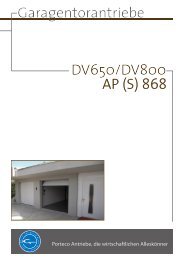
6.1 CONNECTOR CONFIGURATION OF THE INTEGRA CONTROL PANEL<br />
JMP2<br />
42<br />
3<br />
1<br />
4 2<br />
8<br />
4<br />
2<br />
1<br />
3<br />
5<br />
1<br />
X3: Connector set to the finger scanner<br />
Pin No. Cable color Function<br />
1 Yellow RS485 communication (terminal 2)<br />
2 Green RS485 communication (terminal 1)<br />
3 Brown Power supply (terminal 3)<br />
4 White Power supply (terminal 4)<br />
JMP2: Defines how relay 2 should work<br />
Normally open contact Normally closed contact<br />
(NO) (NC)<br />
X6: Relay 1 screw terminal to connect the motor lock<br />
Terminal No. Function<br />
1 Power supply motor lock + (equ. white X1)<br />
2 Power supply motor lock - (equ. brown X1)<br />
3 Swit<strong>ch</strong>ing impulse (swit<strong>ch</strong>ed white X1)<br />
X1: Main connector plug<br />
1<br />
Pin No. Cable color Function<br />
1 Blue Gate input terminal 1<br />
2 Grey Gate input terminal 2<br />
3 Yellow <strong>ekey</strong> TOCA<strong>home</strong> terminal 2<br />
4 Green <strong>ekey</strong> TOCA<strong>home</strong> terminal 1<br />
5 Brown Power supply DC- or AC<br />
6 White Power supply DC+ or AC<br />
7 Pink Relay 2 C<br />
8 Red Relay 2 NO / NC (see JMP1)<br />
2<br />
3