ELBE Programm_D
ELBE Programm_D
ELBE Programm_D

Erfolgreiche ePaper selbst erstellen
Machen Sie aus Ihren PDF Publikationen ein blätterbares Flipbook mit unserer einzigartigen Google optimierten e-Paper Software.
0.100<br />
38<br />
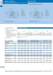
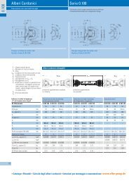
Gelenk-Zwischenwellen<br />
Fehlende Maße und Angaben finden Sie bei den jeweiligen Baugrößen.<br />
Gewünschte Länge „S“ und max. Drehzahl<br />
bei Bestellung bitte angeben!<br />
Baureihe 0.100<br />
Bei Ausnutzung des Nenndrehmomentes ist eine<br />
Überprüfung der Flanschverbindung erforderlich.<br />
Kardan-Gelenk-Zwischenwellen für SKF-Stehlager (gehört nicht zum Lieferumfang)<br />
Bestell-Nr.<br />
Md Nenn Nm<br />
Beugungswinkel ß °<br />
Für Stehlager<br />
A mm<br />
B H7<br />
h6 mm<br />
D mm<br />
E -0,2 mm<br />
G -0,3 mm<br />
H ± 0,1 mm<br />
J B 12 0.109.250 0.110.250 0.112.250 0.113.250 0.148.250 0.158.250 0.117.251 0.120.250 0.122.250 0.122.251<br />
1700 2300 3350 4100 5500 8200 10000 16850 26750 26750<br />
20 20 20 20 20 35 30 30 30 30<br />
SNH 207 SNH 207 SNH 209 SNH 209 SNH 211 SNH 211 SNH 213 SNH 215 SNH 216 SNH 216<br />
90 100 120 120 150 150 180 180 180 225<br />
47 57 75 75 90 90 110 110 110 140<br />
8 8 9 9 10 10 12 14 14 15<br />
2,3 2,3 2,3 2,3 2,8 2,8 2,8 2,8 2,8 4,5<br />
61,1 70,6 88,1 84,1 110,6 110,6 131 131 131 171,5<br />
74,5 84 101,5 101,5 130 130 155,5 155,5 155,5 196<br />
mm 8 8 8 1 0 1 2 1 2 1 6 1 6 1 6 1 6<br />
P1 mm 50 x 2 50 x 3 60 x 4 70 x 4 80 x 4 90 x 4 100 x 5 110 x 6 120 x 6 124 x 8<br />
P2 mm 70 x 3 70 x 3 80 x 4 80 x 4 90 x 4 100 x 4 120 x 5 120 x 6 124 x 8 140 x 6,5<br />
P3 mm 80 x 4 80 x 4 90 x 4 100 x 4 100 x 4 120 x 5 – – – –<br />
R mm 68,5 68,5 71,5 71,5 87,5 87,5 105,5 115,5 135,5 135,5<br />
Smin mm 253 269 305 308 360 420 446 480 540 540<br />
T mm 100 100 100 100 112 112 125 142 147 147<br />
U mm 23 23 23 23 25 25 31 31 33 33<br />
V h9 mm 45 45 55 55 65 65 75 85 90 90<br />
W mm 35 35 45 45 55 55 65 75 80 80<br />
Z mm M16 x 1,5 M16 x 1,5 M20 x 1,5 M20 x 1,5 M32 x 1,5 M32 x 1,5 M45 x 1,5 M45 x 1,5 M45 x 1,5 M45 x 1,5<br />
Gewicht kg 3,95 4,68 7,60 8,59 14,25 17,90 25,64 32,06 – 47,44<br />
Zahnprofil/Keilprofil mm 35 x 31 35 x 31 45 x 41 45 x 41 55 x 50 55 x 50 62x54x20 70x61x20 75x66x22 75x66x22<br />
Anzahl der Flanschlöcher<br />
4 6 8 8 8 8 8 10 10 8<br />
2<br />
Jm (bei Smin) kgm 0,000531 0,00324 0,008786 0,01198 0,02496 0,04510 0,04564 0,1089 – –<br />
2<br />
Jm/100 mm Normalrohr kgm 0,00014 0,00019 0,00044 0,00071 0,00109 0,00157 0,00265 0,00418 – –<br />
G (bei Smin) kg<br />
4,0 4,7 7,5 9,0 13,3 18,5 25,9 31,7 46,0 47,5<br />
G/100 mm Normalrohr kg<br />
0,24 0,35 0,55 0,65 0,75 0,85 1,17 1,54 1,69 2,29<br />
ϕ (bei Smin) ∠° 1,1 1,2 1,5 1,7 1,6 2,2 2,0 2,2 – –<br />
ϕ/100 mm Normalrohr ∠° 0,33 0,38 0,32 0,30 0,23 0,25 0,21 0,20 – –<br />
� Katalog � Ersatzteile � Gelenkwellen-Berechnung � Einbau- und Wartungshinweise � www.elbe-group.de<br />
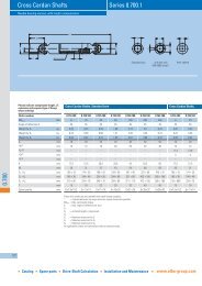
Größe 0.109–0.122<br />
Fehlende Maße und Angaben finden Sie bei den jeweiligen Baugrößen.<br />
Flanschbilder entnehmen Sie bitte bei Kardan-Gelenk-Zwischenwellen ohne Stehlager.<br />
Gewünschte Länge „S“ und max. Drehzahl<br />
bei Bestellung bitte angeben!<br />
Bestell-Nr.<br />
Md Nenn Nm<br />
Beugungswinkel ß °<br />
Stehlager einzeln<br />
A mm<br />
B H7<br />
h6 mm<br />
b mm<br />
D mm<br />
d mm<br />
E -0,2 mm<br />
G -0,3 mm<br />
H ± 0,1 mm<br />
J B 12 mm<br />
P1 mm<br />
P2 mm<br />
P3 mm<br />
R mm<br />
Smin mm<br />
T mm<br />
U mm<br />
V mm<br />
W mm<br />
X mm<br />
Z mm<br />
Zahnprofil/Keilprofil mm<br />
Anzahl der Flanschlöcher<br />
2<br />
Jm (bei Smin) kgm<br />
2<br />
Jm/100 mm Normalrohr kgm<br />
G (bei Smin) kg<br />
G/100 mm Normalrohr kg<br />
ϕ (bei Smin) ∠°<br />
ϕ/100<br />
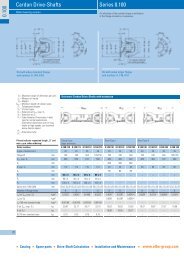
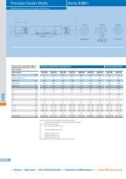
ß = max.<br />
mm Normalrohr<br />
Beugungwinkel pro Gelenk<br />
∠°<br />
Jm = Massenträgheitsmoment<br />
G = Gewicht<br />
Smin = Mindestlänge der Rohrausführungen<br />
Md Nenn 1700–26750 Nm Md Grenz 2200–35000 Nm<br />
Kardan-Gelenk-Zwischenwellen kpl. mit Elastik-Stehlager<br />
0.109.260 0.110.260 0.112.260 0.113.260 0.148.260 0.158.260 0.117.261 0.120.260<br />
1700 2300 3350 4100 5500 8200 10000 16850<br />
20 20 20 20 20 35 30 30<br />
1000958350 1000958350 1000958450 1000958450 1000958500 1000958550 1000958600 1000958700<br />
90 100 120 120 150 150 180 180<br />
47 57 75 75 90 90 110 110<br />
45 45 58 58 58 60 60 63,5<br />
8 8 9 9 10 12 12 14<br />
12,8 12,8 13 13 14,2 15 15 16<br />
2,3 2,3 2,3 2,3 2,3 2,8 2,8 2,8<br />
61,1 70,6 88,1 84,1 110,6 110,6 133 131<br />
74,5 84 101,5 101,5 130 130 155,5 155,5<br />
8 8 8 10 12 12 16 16<br />
50 x 2 50 x 3 60 x 4 70 x 4 80 x 4 90 x 4 100 x 5 110 x 6<br />
70 x 3 70 x 3 80 x 4 80 x 4 90 x 4 100 x 4 120 x 5 120 x 6<br />
80 x 4 80 x 4 90 x 4 100 x 4 100 x 4 120 x 5 – –<br />
68,3 68,3 71,3 71,5 87,5 95 100 107<br />
238 254 293 296 339 410 405 425<br />
58,8 58,8 70 70 70 71,5 80 85,5<br />
168 168 193,6 193,6 193,6 193,6 200 219,2<br />
198 198 228 228 228 230 243 260<br />
35 35 45 45 50 55 60 70<br />
73 69 – – – – – –<br />
M16 x 1,5 M16 x 1,5 M20 x 1,5 M20 x 1,5 M32 x 1,5 M32 x 1,5 M45 x 1,5 M45 x 1,5<br />
35 x 31 35 x 31 45 x 41 45 x 41 50 x 45 55 x 50 60x2,5x22 70x2,5x26<br />
4 6 8 8 8 8 8 10<br />
0,000514 0,00322 0,008748 0,01194 0,02485 0,04503 0,04523 0,10788<br />
0,00014 0,00019 0,00044 0,00071 0,00109 0,00157 0,00265 0,00418<br />
5,40 6,18 9,99 10,69 16,12 20,05 28,40 34,06<br />
0,24 0,35 0,55 0,65 0,75 0,85 1,17 1,54<br />
1,04 1,14 1,45 1,65 1,5 2,15 1,8 1,95<br />
P1 = Rohr-Ø. Fettgedruckte Maße sind<br />
0,33 0,38 0,32 0,30<br />
Vorzugs-Ø, größere Ø für lange<br />
Gelenkwellen unter hohen Drehzahlen,<br />
siehe techn. Anhang Bereich Drehzahl<br />
P2 =alternative<br />
Rohr-Ø<br />
P3 =<br />
0,23 0,25 0,21 0,20<br />
� Service-Telefon Inland* �<br />
0180 – 3 – 435 365<br />
* 9Cent/Min.<br />
� Service-Telefon Ausland �<br />
+49 (0) 71 42 / 353-0<br />
39<br />
0.100