Einbauanleitung: Elektroanlage für Anhängevorrichtung ... - MVG
Einbauanleitung: Elektroanlage für Anhängevorrichtung ... - MVG
Einbauanleitung: Elektroanlage für Anhängevorrichtung ... - MVG

Create successful ePaper yourself
Turn your PDF publications into a flip-book with our unique Google optimized e-Paper software.
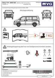
Installation Instructions:Electrical System for Towing HitchInstalling the electrical kit17. Insert the red 12-fold connector housing and the black 16-fold connector housing into theintended slots of the trailer connection unit (Fig. 1/3) and let them lock into place.18. Connect the brown wires with the eyelets to the vehicle’s ground point (Fig. 1/5) at the backon the left.19. Lay the cable set along the vehicle’s cable harnesses / ducts to the area of the networkcontrol unit on the left side at the front of the vehicle (Fig. 1/1).20. 20-22: Vehicles with BCM (Body Control Module) 2009>: On the BCM unit, unlatch thebrown plug (slot C) and open the contact holder by sliding. Unlatch the following wires andinsert into the 3-pin, black bushing housing located on the wire set:- Wire orange/brown from chamber 16 in chamber 1 enclosed black housing.- Wire orange/green from chamber 15 in chamber 3 enclosed black housing.- Wire black/red from chamber 17 in chamber 2 enclosed white housing.21. From the wire set, insert the single wires orange/brown, orange/green and black/red into theproper coloured, vacated chambers 15, 16 and 17 of the brown plug.22. Reconnect the black contact holders with each other by sliding, snapping in the brown covercap and plugging the plug back on the BCM unit (slot C) and latching.23. Vehicles with BSG: Open the red latch on the network control unit by shifting it, disconnectthe black 12-pin connector (position G) from the network control unit and open the latch.Unlock the following cables and insert it into the black 3-pin socket housing provided on thecable set:- The orange/brown cable from compartment 7 into compartment 1.- The orange/green cable from compartment 8 into compartment 3.24. Insert the individual orange/brown and orange/green cables of the cable set into the now freecompartments 7 and 8 of the 12-pin plug as indicated by the colours.25. Close the locking mechanism and re-insert the plug into the network control unit.26. Disconnect the black 16-pin connector (position E) from the network control unit and openlatch. Unlock the following cable and insert it into the white 3-pin socket housing provided onthe cable set:- The cable (BLS, often black/red) from compartment 2 into compartment 2.27. Insert the individual black/red cable of the cable set into the now free compartment 2 of the16-pin plug and close the latch.28. Connect the connector to the network control unit and close the red latch again.29. Fit the now open 3-pin black and white housings together.30. Remove the black cover of the fuse carrier (Fig. 1/2) and open the lilac latch by shifting it.31. Golf, Jetta, Octavia and Passat Coupé: Take the fuse-protected cable out of compartment4 (terminal 15) and insert it into the 1-pin housing on the cable set. Re-insert the individualblack/blue cable of the cable set into comportment 4 of the fuse carrier. Fit the now open 1-pin housings together.32. Golf Plus, Touran, Tiguan, Passat, Leon and Superb: Insert the single black/blue cable ofthe cable set into the fuse-protected side of a suitable fuse compartment that is alreadyequipped with terminal 15. Insert the supplied 5A fuse into this fuse compartment.20 321 600 391 101 - 013 - 26/09 VW Universal