313 222 600 001 (Siarr: 09-79) - WESTFALIA-Automotive GmbH
313 222 600 001 (Siarr: 09-79) - WESTFALIA-Automotive GmbH 313 222 600 001 (Siarr: 09-79) - WESTFALIA-Automotive GmbH
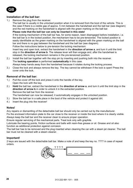
Installation of the ball bar: 1.) Remove the plug from the receiver. The ball bar is usually in the unlocked position when it is removed from the boot of the vehicle. This is the case if there is a visible gap of approx. 5 mm between the handwheel and the ball bar (see diagram) and the red marking on the handwheel is aligned with the green marking on the ball bar. Please note that the ball bar can only be inserted in this state! If the locking mechanism of the ball bar has, for some reason, been disengaged before installation, i.e. the ball bar is in the locked position, the mechanism has to be pre-tensioned. The locked position is easily identifiable as the green marking on the handwheel is aligned with the green marking on the ball bar and there is no gap between the handwheel and the ball bar (see diagram). Follow the instructions below to pre-tension the locking mechanism: Insert key and open lock, extract the handwheel in the direction of arrow a, and turn it until the limit stop in the direction of arrow b. The release lever will then engage and, after the handwheel is released, the locking mechanism remains in the pre-tensioned position. 2.) Install the ball bar together with the stop pin by inserting and pushing both into the receiver. The locking operation is performed automatically in this case. Always keep hands away from the handwheel because it rotates during the locking process. 3.) Close the lock and always remove the key. The key cannot be withdrawn if the lock is open! Press the cover onto the lock. Removal of the ball bar: 1.) Pull the cover off the lock and press it onto the handle of the key. Open the lock with the key. 2.) Hold the ball bar, extract the handwheel in the direction of arrow a, and turn it until the limit stop in the direction of arrow b in order to unlock it in the extracted position. Remove the ball bar from the receiver. The handwheel can now be released; it automatically engages in the unlocked position. 3.) Stow the ball bar in a safe place in the boot of the vehicle and protect it against dirt. 4.) Insert the plug into the receiver! Notes! Any repairs or dismantling of the detachable ball bar should only be carried out by the manufacturer. Fix the enclosed information plate to the car close to the receiver or inside the boot where it is clearly visible. Always keep the ball bar and the receiver clean to ensure proper operation. Ensure regular servicing of the mechanical parts. Treat lock only with graphite. Lubricate the bearing points, friction surfaces and balls with resin-free grease or oil. Grease and oil also function as additional protection against corrosion. The ball bar has to be removed and the plug inserted when cleaning the car with a steam jet cleaner. The ball bar must not be cleaned with a steam cleaner. Important! 2 keys are issued with the detachable ball bar. Make a note of and keep the key no. in case of repeat orders. 28 313 222 691 101 - 005
Οδηγίες λειτουργίας για κινητές ράβδους σφαίρας Προσοχή! Ελέγχετε πριν από κάθε χρήση το σωστό μαντάλωμα της κινητής ράβδου σφαίρας, και συγκεκριμένα τα ακόλουθα στοιχεία: • Το πράσινο σημάδι του χειροτροχού συμπίπτει με την πράσινη περιοχή της ράβδου σφαίρας. • Ο χειρότροχος ακουμπά στη ράβδο σφαίρας (χωρίς διάκενο). • Η κλειδαριά είναι κλειδωμένη και το κλειδί βγαλμένο. O τροχός δεν τραβιέται προς τα έξω. • Η ράβδος πρέπει να εφαρμόζει τελείως σταθερά στο σωλήνα υποδοχής. Ελέγξτε ανακινώντας με το χέρι. Εάν και εφόσον ο έλεγχος των ανωτέρω 4 σημείων δεν αποβεί ικανοποιητικός, επαναλάβετε τη συναρμολόγηση. Σε περίπτωση που δεν πληρούνται και ένα μόνο από τα ανωτέρω σημεία, δεν επιτρέπεται να χρησιμοποιήσετε τη διάταξη ζεύξης. Υπάρχει κίνδυνος ατυχήματος. Απευθυνθείτε στον κατασκευαστή. Η συναρμολόγηση και αποσυναρμολόγηση της ράβδου σφαίρας εκτελείται χωρίς πρόβλημα με κανονική δύναμη χεριού. Μην χρησιμοποιείτε ποτέ βοηθητικά μέσα, εργαλεία κτλ., διότι μπορεί έτσι να προκληθούν ζημιές στο μηχανισμό. Ποτέ μην απασφαλίζετε τη ράβδο όταν έχει προσδεθεί ρυμούλκα ή άλλο φορτίο! Όταν οδηγείτε χωρίς ρυμούλκα ή άλλο φορτίο πρέπει να αφαιρείτε τη ράβδο σφαίρας και να τοποθετείτε πάντα το κατάλληλο πώμα στο σωλήνα υποδοχής! Προσέχετε το ιδιαίτερα, όταν η σφαίρα καλύπτει εν μέρει την πινακίδα οχήματος ή το φωτισμό. Κινητή ράβδος σφαίρας 1 3 3 13 8 2 5 4 10 9 11 12 b a 7 6 1 Σωλήνας υποδοχής 2 Ράβδος σφαίρας 3 Σφαίρες μανταλώματος 4 Μοχλός απελευθέρωσης 5 Χειροτροχός 6 Κάλυμμα 7 Κλειδί 8 Κόκκινο σημάδι (Χειρότροχος) 9 Πράσινο σημάδι (Χειρότροχος) 10 Πράσινο σημάδι (ράβδος σφαίρας) 11 Σύμβολο (απασφάλιση) 12 Πώμα 13 Βλήτρο εισαγωγής 14 Χωρίς διάκενο ανάμεσα στα σημεία 2 και 5 15 Διάκενο ύψους περίπου 5 mm Θέση ασφάλισης, κατά τη χρήση 2 5 1 5 2 14 Θέση απασφάλισης, βγαλμένη 2 5 3 15 2 3 13 5 10 9 6 7 10 8 7 313 222 691 101 - 005 29
- Page 1 and 2: Anhängevorrichtung Montage- und Be
- Page 3 and 4: Nationale Richtlinien über die Anb
- Page 5 and 6: Nasjonale retningslinjer om godkjen
- Page 7 and 8: 313 222 691 101 - 005 7
- Page 9 and 10: 313 222 691 101 - 005 9
- Page 11 and 12: 313 222 691 101 - 005 11
- Page 13 and 14: Der Freiraum nach Anhang VII, Abbil
- Page 15 and 16: Bedienungsanleitung für abnehmbare
- Page 17 and 18: Návod k použití odnímatelné ty
- Page 19 and 20: Betjeningsvejledning til aftagelig
- Page 21 and 22: Instrucciones para el manejo de la
- Page 23 and 24: Notice d’utilisation de la rotule
- Page 25 and 26: Irrotettavan vetopään käyttöohj
- Page 27: Operating instructions for the deta
- Page 31 and 32: Levehető vonóhorog használati ut
- Page 33 and 34: Istruzioni per l’uso della barra
- Page 35 and 36: Bruksanvisning for avtakbar kulesta
- Page 37 and 38: Bedieningshandleiding voor de afnee
- Page 39 and 40: Instrukcja obsługi zdejmowanego dr
- Page 41 and 42: Инструкция по эксп
- Page 43 and 44: Bruksanvisning för avtagbar dragku
Installation of the ball bar:<br />
1.) Remove the plug from the receiver.<br />
The ball bar is usually in the unlocked position when it is removed from the boot of the vehicle. This is<br />
the case if there is a visible gap of approx. 5 mm between the handwheel and the ball bar (see diagram)<br />
and the red marking on the handwheel is aligned with the green marking on the ball bar.<br />
Please note that the ball bar can only be inserted in this state!<br />
If the locking mechanism of the ball bar has, for some reason, been disengaged before installation, i.e.<br />
the ball bar is in the locked position, the mechanism has to be pre-tensioned. The locked position is<br />
easily identifiable as the green marking on the handwheel is aligned with the green marking on the ball<br />
bar and there is no gap between the handwheel and the ball bar (see diagram).<br />
Follow the instructions below to pre-tension the locking mechanism:<br />
Insert key and open lock, extract the handwheel in the direction of arrow a, and turn it until the limit<br />
stop in the direction of arrow b. The release lever will then engage and, after the handwheel is<br />
released, the locking mechanism remains in the pre-tensioned position.<br />
2.) Install the ball bar together with the stop pin by inserting and pushing both into the receiver.<br />
The locking operation is performed automatically in this case.<br />
Always keep hands away from the handwheel because it rotates during the locking process.<br />
3.) Close the lock and always remove the key. The key cannot be withdrawn if the lock is open! Press the<br />
cover onto the lock.<br />
Removal of the ball bar:<br />
1.) Pull the cover off the lock and press it onto the handle of the key.<br />
Open the lock with the key.<br />
2.) Hold the ball bar, extract the handwheel in the direction of arrow a, and turn it until the limit stop in the<br />
direction of arrow b in order to unlock it in the extracted position.<br />
Remove the ball bar from the receiver.<br />
The handwheel can now be released; it automatically engages in the unlocked position.<br />
3.) Stow the ball bar in a safe place in the boot of the vehicle and protect it against dirt.<br />
4.) Insert the plug into the receiver!<br />
Notes!<br />
Any repairs or dismantling of the detachable ball bar should only be carried out by the manufacturer.<br />
Fix the enclosed information plate to the car close to the receiver or inside the boot where it is clearly visible.<br />
Always keep the ball bar and the receiver clean to ensure proper operation.<br />
Ensure regular servicing of the mechanical parts. Treat lock only with graphite.<br />
Lubricate the bearing points, friction surfaces and balls with resin-free grease or oil. Grease and oil also<br />
function as additional protection against corrosion.<br />
The ball bar has to be removed and the plug inserted when cleaning the car with a steam jet cleaner. The ball<br />
bar must not be cleaned with a steam cleaner.<br />
Important!<br />
2 keys are issued with the detachable ball bar. Make a note of and keep the key no. in case of repeat<br />
orders.<br />
<br />
28<br />
<strong>313</strong> <strong>222</strong> 691 101 - 005


