Audi A6, Limousine und Avant, 1997 - Home - AHK - RATGEBER
Audi A6, Limousine und Avant, 1997 - Home - AHK - RATGEBER
Audi A6, Limousine und Avant, 1997 - Home - AHK - RATGEBER

Create successful ePaper yourself
Turn your PDF publications into a flip-book with our unique Google optimized e-Paper software.
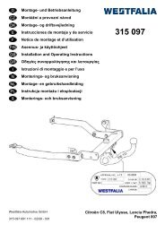
Operating instructions for the detachable ball bar<br />
Installation instructions:<br />
1.) Remove the covering from the boot. Remove the rear bumper cover, the rear bumper and the <strong>und</strong>erbody<br />
covering. Unscrew the impact shock absorbers on the left and right from the aluminium bumper support.<br />
The impact shock absorbers and the <strong>und</strong>erbody covering are no longer required. The screws X will be<br />
reused later. Cut out the aluminium bumper support in the middle area using the template provided. Cut<br />
out the shaded area Z from the bumper cover using the template provided (see Diagram I).<br />
2.) Remove exhaust holder and shielding plate(s) (for front-wheel drive only on left, for Quattro on both<br />
sides). Remove the linen adhesive strip Y from the bottom of the vehicle. Secure the shackles 3 at "b"<br />
using blind rivet 4 (see Diagram II). Then secure shielding plate(s) and exhaust holder (see above)<br />
again.<br />
3.) Position coupling ball with bracket base 1 in aluminium bumper carrier.<br />
For vehicles up to model year 2001 and all V8 models, position plates 9 at left and right <strong>und</strong>er<br />
bracket of ball and coupling and pull aluminium bumper as far to the rear as possible. For vehicles as of<br />
model year 2002 excluding V8 models, position plates 9 at left and right on bracket of ball and<br />
coupling and pull aluminium bumper as far to the front as possible.<br />
Secure coupling ball with bracket base and aluminium bumper at „a“ using screws X (see section 1),<br />
washers 8.4 7 and nuts M8 8. Tightening torque at „a“ is 20 Nm + 2Nm.<br />
4.) (see Diagram III) Mount the towing hitch basic section 1 on the vehicle with the pre-assembled<br />
aluminium bumper support. Move the side parts of the towing hitch basic section 1 into the vehicle´s<br />
longitudinal beams here. Insert the screws 5 with the washers 6 at "c" and "d" both on the left and right<br />
and tighten the towing hitch basic section 1.<br />
At "c" and "d" the starting torque is 55 Nm ± 5 Nm. At "c" and "d" check the starting torque after 15<br />
minutes at the earliest and correct if necessary.<br />
5.) Put the socket connection cable of the electrical assembly in place (see installation instructions for<br />
electrical accessory set).<br />
6.) Place the covering in the boot and secure. Match the bumper cover to the vehicle contour and mount.<br />
Adhere information plate „detachable ball neck“ visibly onto inside of boot.<br />
7.) Install the electrical assembly fully (see installation instructions for electrical accessory set).<br />
8.) (see drawing IV) Take off the detachable ball rod and insert the plug 10 into the mounting tube. Stow the<br />
detachable ball rod together with the gloves 13 in the bag 11.<br />
On Saloon models, tie the bag 11 with the detachable ball rod tight in the spare wheel using the strap 12.<br />
On the <strong>Avant</strong> place the detachable ball rod into the car tool kit stowage point and attach.<br />
Important!<br />
Check the following points to ensure correct locking of the detachable ball bar before each journey:<br />
• The green marking on the handwheel is aligned with the green area on the ball bar.<br />
• The handwheel is resting against the ball bar (no gap).<br />
• The lock is closed and the key is withdrawn. The handwheel cannot be pulled out.<br />
• The ball bar must be fully inserted into the receiver and be tight. Check by shaking it.<br />
Repeat the installation procedure if any of the 4 checks is not satisfactory.<br />
To avoid the risk of accidents the towing device should not be used if any of the requirements is not met.<br />
Contact the manufacturer if this occurs.<br />
The ball bar can be easily installed and removed with the normal force of your hands.<br />
Never use any sort of aids or tools etc. as this might damage the mechanism.<br />
Never unlock if trailers are attached or load bearing implements mounted!<br />
Always remove the ball bar and insert the plug into the receiver for journeys without a trailer or load bearing<br />
implement. This is especially important if the tow ball impedes sight of the vehicle’s registration number or<br />
lights.<br />
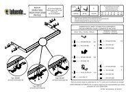
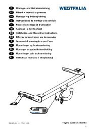
Detachable ball bar<br />
8<br />
3<br />
1<br />
3<br />
13<br />
2 4<br />
5<br />
10 9<br />
11<br />
12<br />
b<br />
a<br />
7<br />
6<br />
1 Receiver<br />
2 Ball bar<br />
3 Locking balls<br />
4 Release lever<br />
5 Handwheel<br />
6 Cover<br />
7 Key<br />
8 Red marking (handwheel)<br />
9 Green marking (handwheel)<br />
10 Green marking (ball bar)<br />
11 Symbol (release)<br />
12 Plug<br />
13 Stop pin<br />
14 No gap between 2 and 5<br />
15 Gap of approx. 5 mm<br />
Subject to alteration.<br />
Locked position, operating condition<br />
2<br />
5<br />
1<br />
5<br />
2<br />
14<br />
Unlocked position, ball bar not mounted<br />
2<br />
5<br />
3<br />
3<br />
13<br />
5<br />
15<br />
2<br />
10<br />
9<br />
6<br />
7<br />
10<br />
8<br />
7<br />
14<br />
35