Audi A6, Limousine und Avant, 1997 - Home - AHK - RATGEBER
Audi A6, Limousine und Avant, 1997 - Home - AHK - RATGEBER
Audi A6, Limousine und Avant, 1997 - Home - AHK - RATGEBER

You also want an ePaper? Increase the reach of your titles
YUMPU automatically turns print PDFs into web optimized ePapers that Google loves.
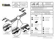
Installation of the ball bar:<br />
1.) Remove the plug from the receiver.<br />
The ball bar is usually in the unlocked position when it is removed from the boot of the vehicle. This is<br />
the case if there is a visible gap of approx. 5 mm between the handwheel and the ball bar (see diagram)<br />
and the red marking on the handwheel is aligned with the green marking on the ball bar.<br />
Please note that the ball bar can only be inserted in this state!<br />
If the locking mechanism of the ball bar has, for some reason, been disengaged before installation, i.e.<br />
the ball bar is in the locked position, the mechanism has to be pre-tensioned. The locked position is<br />
easily identifiable as the green marking on the handwheel is aligned with the green marking on the ball<br />
bar and there is no gap between the handwheel and the ball bar (see diagram).<br />
Follow the instructions below to pre-tension the locking mechanism:<br />
Insert key and open lock, extract the handwheel in the direction of arrow a, and turn it until the limit<br />
stop in the direction of arrow b. The release lever will then engage and, after the handwheel is<br />
released, the locking mechanism remains in the pre-tensioned position.<br />
2.) Install the ball bar together with the stop pin by inserting and pushing both into the receiver.<br />
The locking operation is performed automatically in this case.<br />
Always keep hands away from the handwheel because it rotates during the locking process.<br />
3.) Close the lock and always remove the key. The key cannot be withdrawn if the lock is open! Press the<br />
cover onto the lock.<br />
Removal of the ball bar:<br />
1.) Pull the cover off the lock and press it onto the handle of the key.<br />
Open the lock with the key.<br />
2.) Hold the ball bar, extract the handwheel in the direction of arrow a, and turn it until the limit stop in the<br />
direction of arrow b in order to unlock it in the extracted position.<br />
Remove the ball bar from the receiver.<br />
The handwheel can now be released; it automatically engages in the unlocked position.<br />
3.) Stow the ball bar in a safe place in the boot of the vehicle and protect it against dirt.<br />
4.) Insert the plug into the receiver!<br />
Notes!<br />
Any repairs or dismantling of the detachable ball bar should only be carried out by the manufacturer.<br />
Fix the enclosed information plate to the car close to the receiver or inside the boot where it is clearly visible.<br />
Always keep the ball bar and the receiver clean to ensure proper operation.<br />
Ensure regular servicing of the mechanical parts. Treat lock only with graphite.<br />
Lubricate the bearing points, friction surfaces and balls with resin-free grease or oil. Grease and oil also<br />
function as additional protection against corrosion.<br />
The ball bar has to be removed and the plug inserted when cleaning the car with a steam jet cleaner. The ball<br />
bar must not be cleaned with a steam cleaner.<br />
Important!<br />
2 keys are issued with the detachable ball bar. Make a note of and keep the key no. ???? in case of repeat<br />
orders.<br />
? ? ? ?<br />
Asennusohjeet:<br />
1.) Irrottakaa tavaratilan verhous. Irrottakaa takapuskurin peite, takapuskuri ja alapohjan verhous.<br />
Ruuvatkaa irti iskunvaimentimet oikealta ja vasemmalta alumiiinisesta puskurin kiinnityskonsolista.<br />
Iskunvaimentimia ja alapohjan verhousta ei jatkossa enää tarvita. Ruuvit X otetaan talteen myöhempää<br />
käyttöä varten. Leikatkaa alumiiiniseen puskurin kiinnityskonsoliin sen keskivaihelle mukana seuranneen<br />
mallineen mukainen aukko. Leikatkaa puskurin peitteeseen mukana seuranneen mallineen viivoitetun<br />
alueen Z mukainen aukko .<br />
2.) Irrottakaa pakosarjan kiinnikkeet ja suojuspelti/-pellit. (etuvetoisissa vain vasemmalla, Quattrossa<br />
molemmin puolin) (kts. piirros II) Poistakaa kangastarranauha Y ajoneuvon alapuolelta. Kiinnittäkää<br />
laipat 3 kohtiin "b" niitein 4 (kts. piirros II). Kiinnittäkää lopuksi jälleen suojapelti/-pellit sekä pakosarja<br />
(Kts. yllä).<br />
3.) Asettakaa vetokoukun perusosa 1 alumiinipuskurin kannattimeen.<br />
Ajoneuvomalleissa vuoteen 2001 ja kaikissa V8-malleissa, asettakaa aluslaatat 9 vasemmalla ja<br />
oikealla vetokoukun pidikkeen alle ja vetäkää alumiinipuskuri niin kauas taakse kuin mahdollista.<br />
Vuoden 2002 ajoneuvomalleissa lukuunottamatta V8-malleja, asettakaa aluslaatat 9 vasemmalla ja<br />
oikealla vetokoukun pidikkeen päälle ja työntäkää alumiinipuskuri niin kauas eteen kuin mahdollista.<br />
Ruuvatkaa vetokoukun perusosa ja alumiinipuskuri kohdassa "a" ruuveilla X (ks. kohta 1), prikoilla<br />
8,4 7 ja muttereilla M8 8.<br />
Kiristysmomentti kohdassa "a" on 20 Nm + 2 Nm.<br />
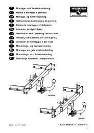
4.) (kts. piirros III) asentakaa vetokoukun perusosa 1 yhdessä esiasennetun alumiinisen puskurinkonsolin<br />
kanssa ajoneuvoon. Tätä varten työntäkää vetokoukun perusosan asennusvarret 1 ajoneuvon<br />
pitkittäispalkkien sisään. Ruuvatkaa Pultit 5 prikkoineen 6 kohtiin "c" ja "d" vasemmalla ja oikealla, ja<br />
kiristäkää vetokoukun perusosa 1 paikalleen vääntömomentille 55 Nm + 5 Nm.<br />
Kohtien "c" ja "d" vääntömomentti on 55 Nm + 5 Nm. Vääntömomentti kohdissa "c" ja "d" on tarkistettava<br />
aikaisintaan 15 minuutin kuluttua ja tarpeen vaatiessa korjattava.<br />
5.) Asentakaa sähkötarvikesarjan mukana oleva sähkörasian liitäntäkaapeli (kts sähkötarvikesarjan<br />
asennusohje).<br />
6.) Laittakaa tavaratilan verhous takaisin paikoilleen ja kiinnittäkää se. Asettakaa puskurinpeite paikalleen<br />
ja muotoilkaa se autoon sopivaksi. Liimatkaa tavaratilan sisäpuolelle näkyvälle paikalle oheinen "<br />
Vetokoukku irrotettavissa pikasalvalla ".<br />
7.) Asentakaa sähkölisätarvikesarja valmiiksi (kts. sähkövarustesarjan asennusohje).<br />
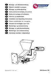
8.) (katso kuva IV) Irrota irrotettava kuulatanko ja aseta sulkutulppa 10 asennusputkeen. Siirrä kuulatanko<br />
hansikkaita 13 käyttäen koteloon 11.<br />
Henkilöautomallissa kiinnitä kuulatangon sisältävä kotelo 11 kiinnityshihnalla 12 varapyörään.<br />
<strong>Avant</strong>-mallissa kiinnitä irrotettava kuulatanko kyljessä olevaan työkalutelineeseen.<br />
Oikeudet muutoksiin pidätetään.<br />
36<br />
13